A few weeks ago, we examined the features of ESP32 module and built a simple hello world program to get ourselves familiar with the board. Today, we will continue our exploration of the ESP32 on a higher level as we will look at how to interface a 16×2 LCD with it.
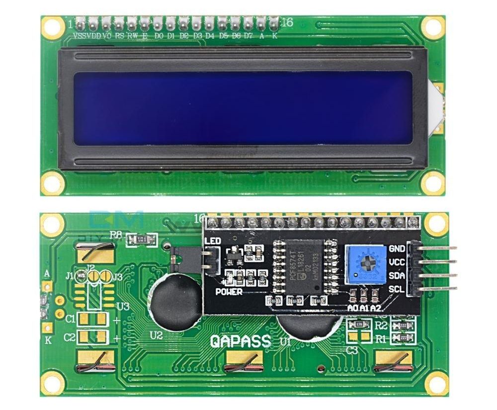
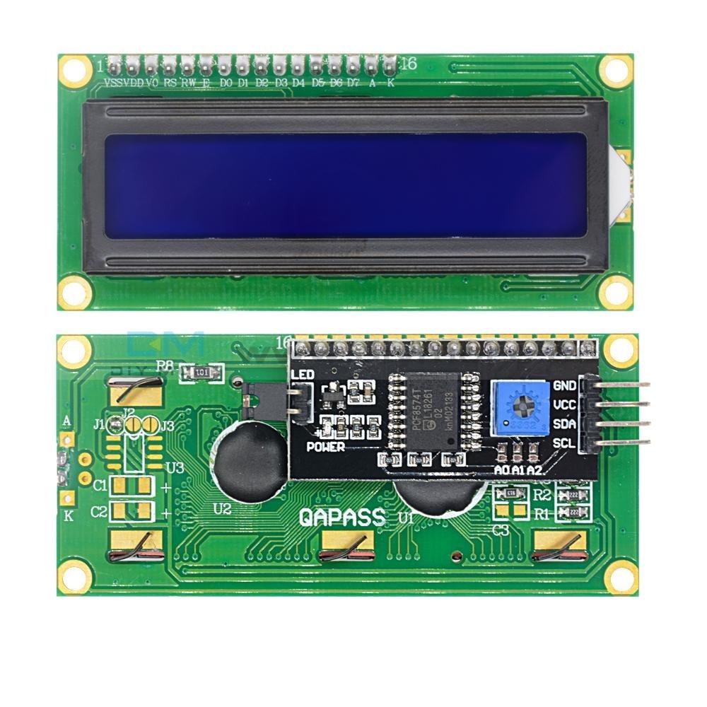
Displays provide a fantastic way of providing feedback to users of any project and with the 16×2 LCD being one of the most popular displays among makers, and engineers, its probably the right way to start our exploration. For today’s tutorial, we will use an I2C based 16×2 LCD display because of the easy wiring it requires. It uses only four pins unlike the other versions of the display that requires at least 7 pins connected to the microcontroller board.
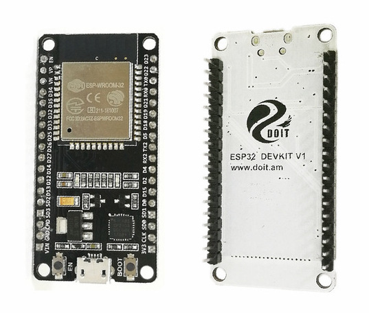
ESP32 comes in a module form, just like its predecessor, the ESP-12e, as a breakout board is usually needed to use the module. Thus when it’s going to be used in applications without a custom PCB, it is easier to use one of the development boards based on it. For today’s tutorial, we will use the DOIT ESP32 DevKit V1 which is one of the most popular ESP32 development boards.
To demonstrate the use of I2C driven LCD with the NodeMCU, we will examine how to display both static and scrolling messages on the LCD.
A few weeks ago, we examined the features of ESP32 module and built a simple hello world program to get ourselves familiar with the board. Today, we will continue our exploration of the ESP32 on a higher level as we will look at how to interface a 16×2 LCD with it.
I2C 16×2 LCD Display
Displays provide a fantastic way of providing feedback to users of any project and with the 16×2 LCD being one of the most popular displays among makers, and engineers, its probably the right way to start our exploration. For today’s tutorial, we will use an I2C based 16×2 LCD display because of the easy wiring it requires. It uses only four pins unlike the other versions of the display that requires at least 7 pins connected to the microcontroller board.
DOIT ESP32 DevKit V1
ESP32 comes in a module form, just like its predecessor, the ESP-12e, as a breakout board is usually needed to use the module. Thus when it’s going to be used in applications without a custom PCB, it is easier to use one of the development boards based on it. For today’s tutorial, we will use the DOIT ESP32 DevKit V1 which is one of the most popular ESP32 development boards.
To demonstrate the use of I2C driven LCD with the NodeMCU, we will examine how to display both static and scrolling messages on the LCD.
Required Components
The following components are required to build this project;
DOIT ESP32 DevKit V1 board
Breadboard
A 16×2 I2C LCD display
Jumper Wires
The breadboard requirement is optional as you can choose to connect the LCD directly to the DOIT devkit board using female-female jumper wires.
Schematics
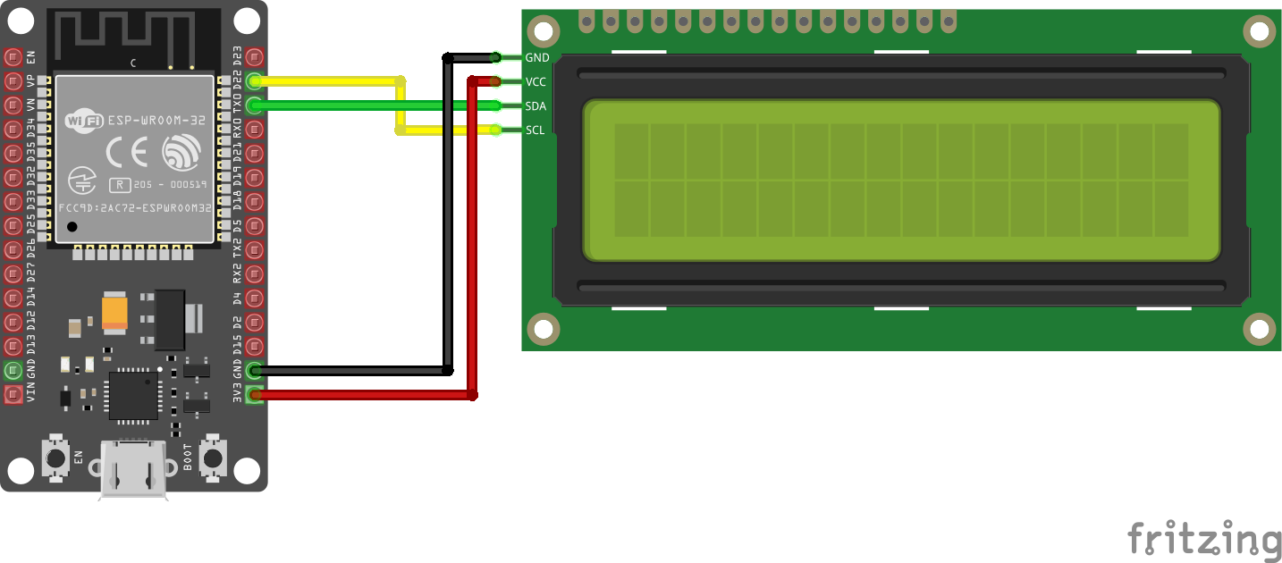
The schematics for this project is relatively simple since we are connecting just the LCD to the DOIT Devkit v1. Since we are using I2C for communication, we will connect the pins of the LCD to the I2C pins of the DevKit. Connect the components as shown below.
Schematics
A pin map showing how the components are connected is shown below.
Due to the power requirements of the LCD, it may not be bright enough when connected to the 3.3v pin of the ESP32. If that is the case, connect the VCC pin of the LCD to the Vin Pin of the ESP32 so it can draw power directly from the connected power source.
Detecting the I2C Address of the LCD
At this point, it is important to note that a special setup is required to enable you to use the Arduino IDE to program ESP32 based boards. We covered this in the introduction to ESP32 tutorial published a few weeks go. So, be sure to check it out.
To be able to easily write the code to interact with the I2C LCD display, we will use the I2C LCD library. The Library possesses functions and commands that make addressing the LCD easy. Download the I2C LCD library from the link attached and install on the Arduino IDE by simply extracting it into the Arduino’s library folder.
Before writing the code for the project, it’s important for us to know the I2C address of the LCD as we will be unable to talk to the display without it.
While some of the LCDs come with the address indicated on it or provided by the seller, in cases where this is not available, you can determine the address by using a simple sketch that sniffs the I2C line to detect what devices are connected alongside their address. This sketch is also a good way to test the correctness of your wiring or to determine if the LCD is working properly.
Copy the code below and paste in the Arduino IDE.
#include <Wire.h>

void setup() {
  Wire.begin();
  Serial.begin(115200);
  Serial.println("\nI2C Scanner");
}

void loop() {
  byte error, address;
  int nDevices;

  Serial.println("Scanning...");

  nDevices = 0;
  for(address = 1; address < 127; address++ )
  {
    // The i2c_scanner uses the return value of
    // the Write.endTransmisstion to see if
    // a device did acknowledge to the address.
    Wire.beginTransmission(address);
    error = Wire.endTransmission();
    if (error == 0) {
      Serial.print("I2C device found at address 0x");
      if (address<16) {
        Serial.print("0");
      }
      Serial.println(address,HEX);
      nDevices++;
    }
    else if (error==4) {
      Serial.print("Unknow error at address 0x");
      if (address<16) {
        Serial.print("0");
      }
      Serial.println(address,HEX);
    }
  }
  if (nDevices == 0) {
    Serial.println("No I2C devices found\n");
  }
  else {
    Serial.println("done\n");
  }
  delay(5000);
}
This sketch basically uses a “for” loop to generate a list of addresses and then sends a begin transmission request to the address. The return value of the Write.endTransmission() function shows if a device exists on that particular address. The address at which a response was received is the address we are a looking for.
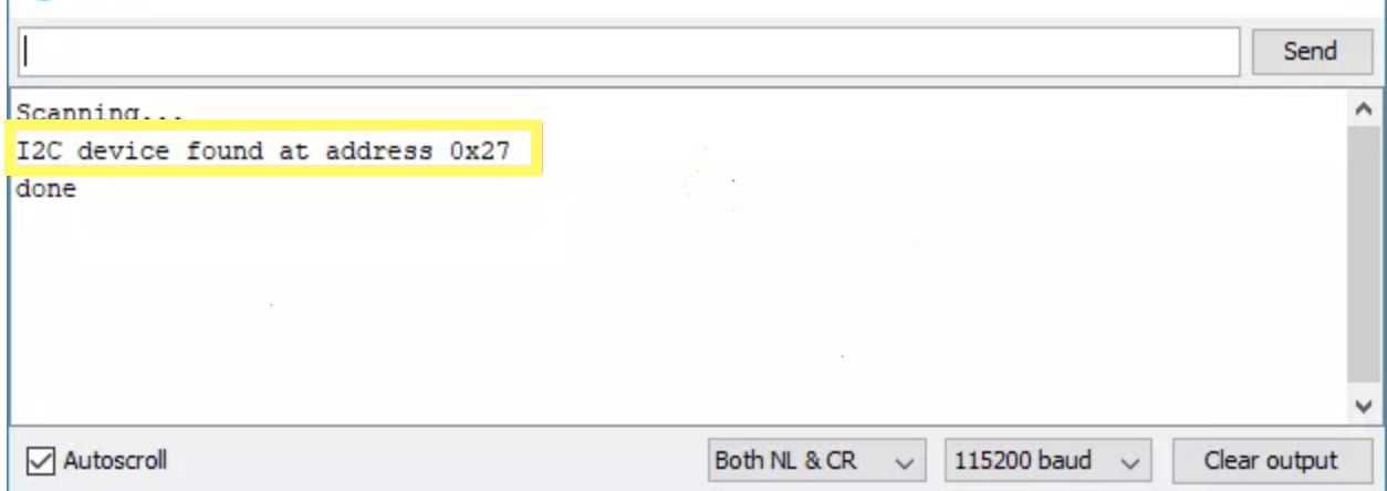
Verify and upload the code to the ESP32 Board and open the serial monitor. You should see the address as shown in the image below:
Device Address
If you keep getting “no devices found”, it might help to take a look at the connections to be sure you didn’t mix things up and you could also go ahead and try 0x27 as the I2C address. This is a common address for most I2C LCD modules from China.
Armed with the address, we can now write the code for this project.
Code
Our task for today’s tutorial is to display both static and scrolling text on the LCD, and to achieve that, we will use the I2C LCD library to reduce the amount of code we need to write. We will write two separate sketches; one to display static texts and the other to display both static andscrolling text.
Static Text
To start with the sketch for static text display, we start the code by including the library to be used for it, which in this case, is the I2C LCD library.
#include <LiquidCrystal_I2C.h>
Next, we create an instance of the I2C LCD library class with the address of the display, the number of columns the display has (16 in this case), and the number of rows (2 in this case) as arguments.
LiquidCrystal_I2C lcd(0x27, 16, 2);
With that done, we proceed to the void setup() function. Here we initialize the display and issue the command to turn the backlight on as it might be off by default depending on the LCD.
Next is the void loop() function. The idea behind the code for the loop is simple, we start by setting the cursor to the column and row of the display where we want the text to start from, and we proceed to display the text using the lcd.print() function. To allow the text to stay on the screen for a while (so its visible) before the loop is reloaded, we delay the code execution for 1000ms.
void loop(){
// set cursor to first column, first row
lcd.setCursor(0, 0);
// print message
lcd.print("Hello, World!");
delay(1000);
// clears the display to print new message
}
The complete code for the project is available below and also attached under the download section.
#include <LiquidCrystal_I2C.h>
// set LCD address, number of columns and rows
// if you don't know your display address, run an I2C scanner sketch
LiquidCrystal_I2C lcd(0x27, 16, 2);
void setup(){
  // initialize LCD
  lcd.init();
  // turn on LCD backlight
  lcd.backlight();
}
void loop(){
  // set cursor to first column, first row
  lcd.setCursor(0, 0);
  // print message
  lcd.print("Hello, World!");
  delay(1000);
  // clears the display to print new message
}
Scrolling Text
For the scrolling text, we will use some code developed by Rui Santos of RandomNerdTutorials.com. This code allows the display of static text on the first row and scrolling text on the second row of the display at the same time.
As usual, we start by including the libraries that we will use for the sketch which in this case is the same I2C LCD library.
Next, we create an instance of the I2C LCD library class with the address of the display, the number of columns the display has (16 in this case), and the number of rows (2 in this case) as arguments.
LiquidCrystal_I2C lcd(0x27, 16, 2);
Next, we create variables to hold the messages to be displayed.
String messageStatic = "Static message";
String messageToScroll = "This is a scrolling message with more than 16 characters";
Next, we create the function to display scrolling text. The function accepts four arguments; the row on which to display the scrolling text, the text to be displayed, the delay time between the shifting of characters, and the number of columns of the LCD.
void scrollText(int row, String message, int delayTime, int lcdColumns) {
  for (int i=0; i < lcdColumns; i++) {
    message = " " + message;
  }
  message = message + " ";
  for (int pos = 0; pos < message.length(); pos++) {
    lcd.setCursor(0, row);
    lcd.print(message.substring(pos, pos + lcdColumns));
    delay(delayTime);
  }
}
Next is the void setup() function. The function stays the same as the one for the static text display as we initialize the display and turn on the backlight.
With that done, we move to the void loop() function. We start by setting the cursor, then we use the print function to display the static text and the scrollText() function is called to display the scrolling text.
void loop(){
// set cursor to first column, first row
lcd.setCursor(0, 0);
// print static message
lcd.print(messageStatic);
// print scrolling message
scrollText(1, messageToScroll, 250, lcdColumns);
}
The complete code for this sketch is available below and also attached under the download section of the tutorial.
// Adapted from the code by
// Rui Santos
// https://randomnerdtutorials.com
#include <LiquidCrystal_I2C.h>
// if you don't know your display address, run an I2C scanner sketch
LiquidCrystal_I2C lcd(0x27, 16, 2);
String messageStatic = "Static message";
String messageToScroll = "This is a scrolling message with more than 16 characters";
// Function to scroll text
// The function acepts the following arguments:
// row: row number where the text will be displayed
// message: message to scroll
// delayTime: delay between each character shifting
// lcdColumns: number of columns of your LCD
void scrollText(int row, String message, int delayTime, int lcdColumns) {
for (int i=0; i < lcdColumns; i++) {
message = " " + message;
}
message = message + " ";
for (int pos = 0; pos < message.length(); pos++) {
lcd.setCursor(0, row);
lcd.print(message.substring(pos, pos + lcdColumns));
delay(delayTime);
}
}
void setup(){
  // initialize LCD
  lcd.init();
  // turn on LCD backlight
  lcd.backlight();
}
void loop(){
// set cursor to first column, first row
lcd.setCursor(0, 0);
// print static message
lcd.print(messageStatic);
// print scrolling message
scrollText(1, messageToScroll, 250, 16);
}
Demo
Ensure your connections are properly done, connect the DOIT Devkit to your PC and upload either of the two sketches. You should see this display come up with the text as shown in the image below.
Demo
That’s it for today’s tutorial guys. Thanks for following this tutorial. This cheap LCD display provides a nice way of providing visual feedback for your project and even though the size of the screen and the quality of the display is limited, with the scrolling function you can increase the amount of text/characters that can be displayed.
Feel free to reach out to me via the comment section, with questions and general comments on the tutorial.
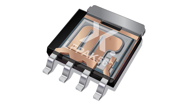
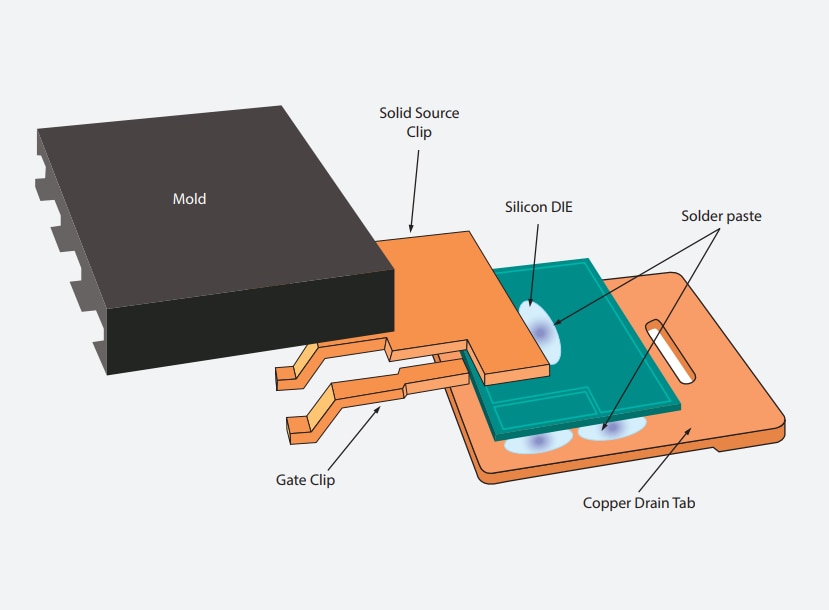
Bipolar transistors in LFPAK56 – the true power package for smart efficiency
These high-power bipolar transistors, housed in LFPAK56 (Power-SO8) packages, deliver DPAK-like thermal and electrical performance in just half the footprint. Offering reliable, energy-efficient performance, they are AEC-Q101 qualified and support high-temperature operation (175 °C).
Features & benefits
27 types up to 100 V and 15 A in single and double confi gurations
High power dissipation (Ptot)
Suitable for high-temperature applications (175 °C)
Space-saving 5 x 6 mm package outline is half the size of equivalent transistors in DPAK, SOT223, and other packages
Low profile (1 mm)
High reliability and mechanical ruggedness thanks to solidcopper clip (no wires)
High energy effi ciency due to less heat generation
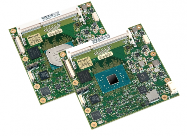
Avnet Integrated has incorporated AMD’s R1000 embedded processor family, based on the Ryzen core architecture, into its COM Express Type 6 modules. The ready-to-use computer on modules (COMs) enable developers to quickly implement the new processor technology in compact embedded systems for a rapid introduction of innovative end products, claims Avnet. The desired performance data can be easily scaled via the processor platform.
The R1000-based module platform in COM Express Compact form factor features high graphics performance that can replace an external solution in price-sensitive applications. Another advantage is the low power dissipation of 12 to 25W. In addition to the R1000 accelerated processing unit (APU) with dual-core, the modules integrate a dual channel DDR4 memory with optional error-correcting code (ECC).
There are common embedded interfaces such as PCI Express and connections for up to three independent 4K displays. Some module variants are designed for the industrial temperature range from -40 to +85 degrees C. The boards, which were developed for the embedded market, are available for at least 10 years from the product launch of the processor, assures Avnet.
Typical areas of use for the R1000-based COM Express module family are applications with high graphics requirements and large data volumes, for example, in medical technology, human machine interface (HMI) systems, gaming and entertainment products.
The R1000 embedded processor family has the same architecture as the AMD V1000 processors. Both processor families are socket-compatible and can be scaled, both in terms of performance and cost, according to the specific application. In addition to the R1000, Avnet Integrated also offers V1000-based product variants to provide customers with the whole range of performance spectrum.
Samples will be available starting August 2019 and volume ramp up expected for the end of 2019.
The company also revealed that integration of R1000 processors into SMARC 2.0 modules is in preparation.
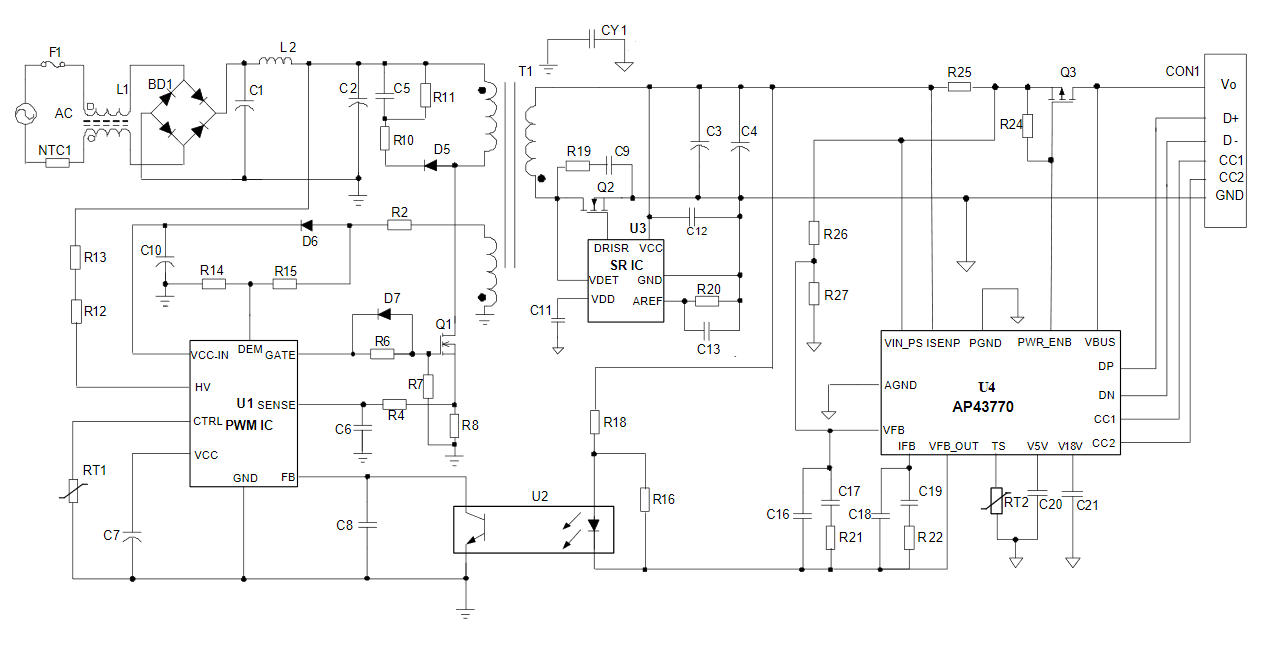
Diodes Incorporated announced the introduction of the AP43770 USB Type-C™ power delivery (PD) controller, a highly integrated solution for implementing PD over USB in fixed and portable devices, and offline power adapters. The AP43770 is well-suited to a range of applications where USB PD is implemented, including AC adapters, power hubs, battery banks, and USB PD converters. It features an embedded microcontroller running firmware compliant with the latest USB Type-C specification and USB PD Revision 3.0 V1.1. Support for Qualcomm® Quick Charge™ (QC) 4/4+ is built into the device. Additionally, the inclusion of QC3.0, QC2.0, and Battery Charging (BC) revision 1.2 and other legacy protocols with auto-detection means that backwards compatibility can be maintained with existing equipment.
The programmable power supply (PPS) feature, introduced with the latest version of the USB PD specification, is also supported by the AP43770. The PPS feature allows the output voltage to vary based on the load requirements; this is communicated using a relevant augmented power data object (APDO). Support for PPS with APDO is implemented in the AP43770 through a constant current and constant voltage (CC/CV) output driver that is adjustable in 50mA steps up to 6A, and 20mV steps between 3V and 20V, respectively.
AP43770 Typical Application Circuit
As USB PD has the potential to deliver high levels of power, the USB eMarker feature is increasingly applied to active cables. The AP43770 includes the necessary support for eMarker technology, in order to detect and identify cables before power is delivered. Cable compensation is also supported.
When coupled with a suitable PWM controller, such as Diodes’ AP3108L, the AP43770 provides a total PD solution. It also features up to 8kb of OTP (for main firmware code) or MTP (for user configurable parameters). MTP memory can be used to set up power specification and protocol options to the manufacturer’s requirements.
The AP43770 is available in the space-saving TSSOP-16 package. Further information is available at www.diodes.com.
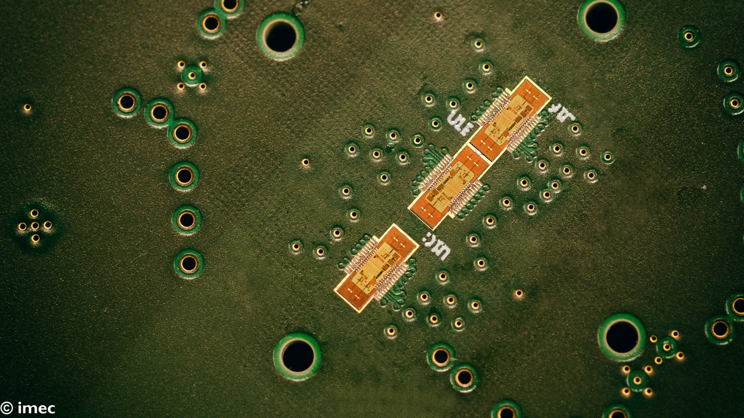
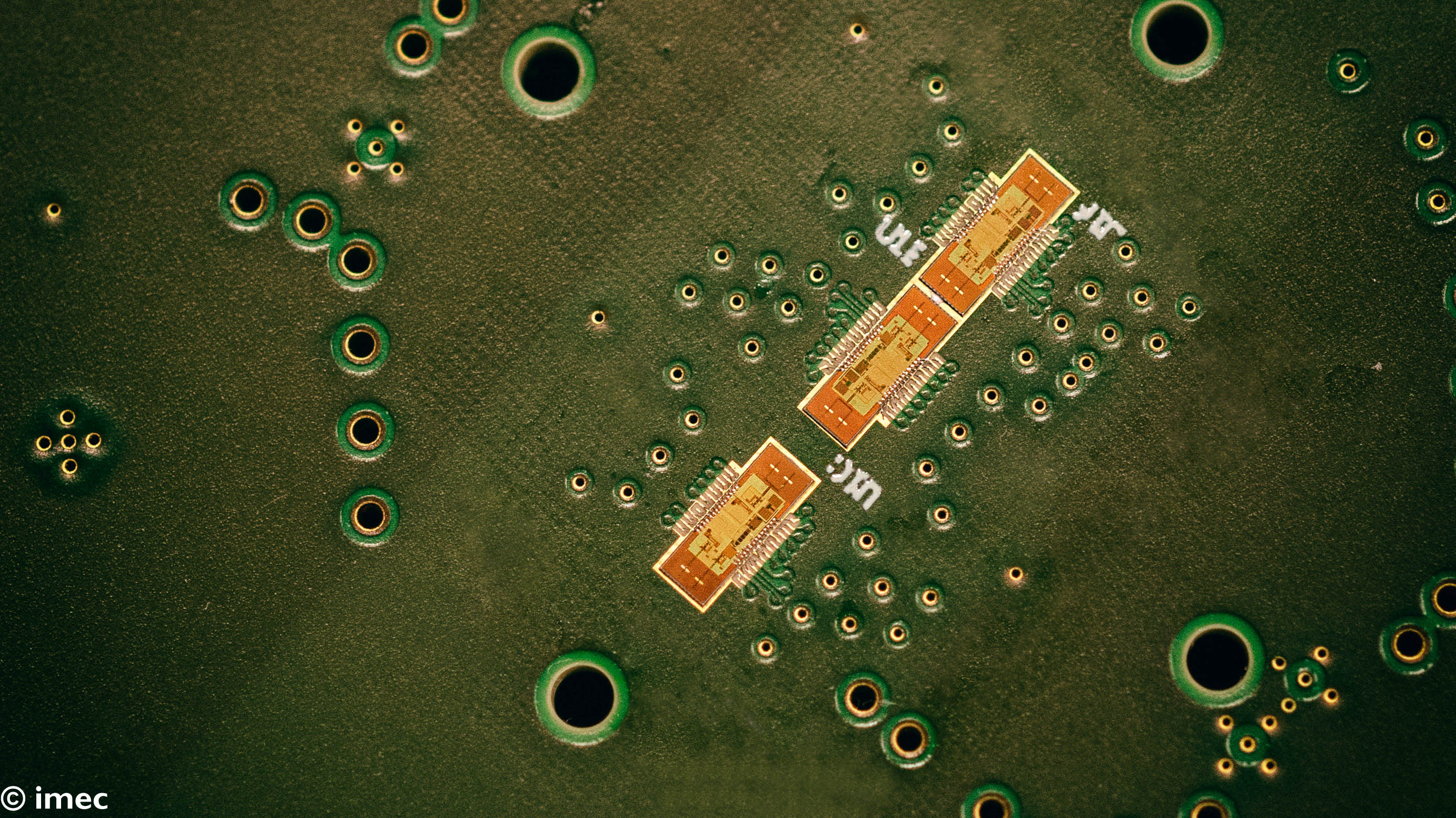
Imec adds machine learning to its 140GHz radar technology to enable intuitive man-machine interactions
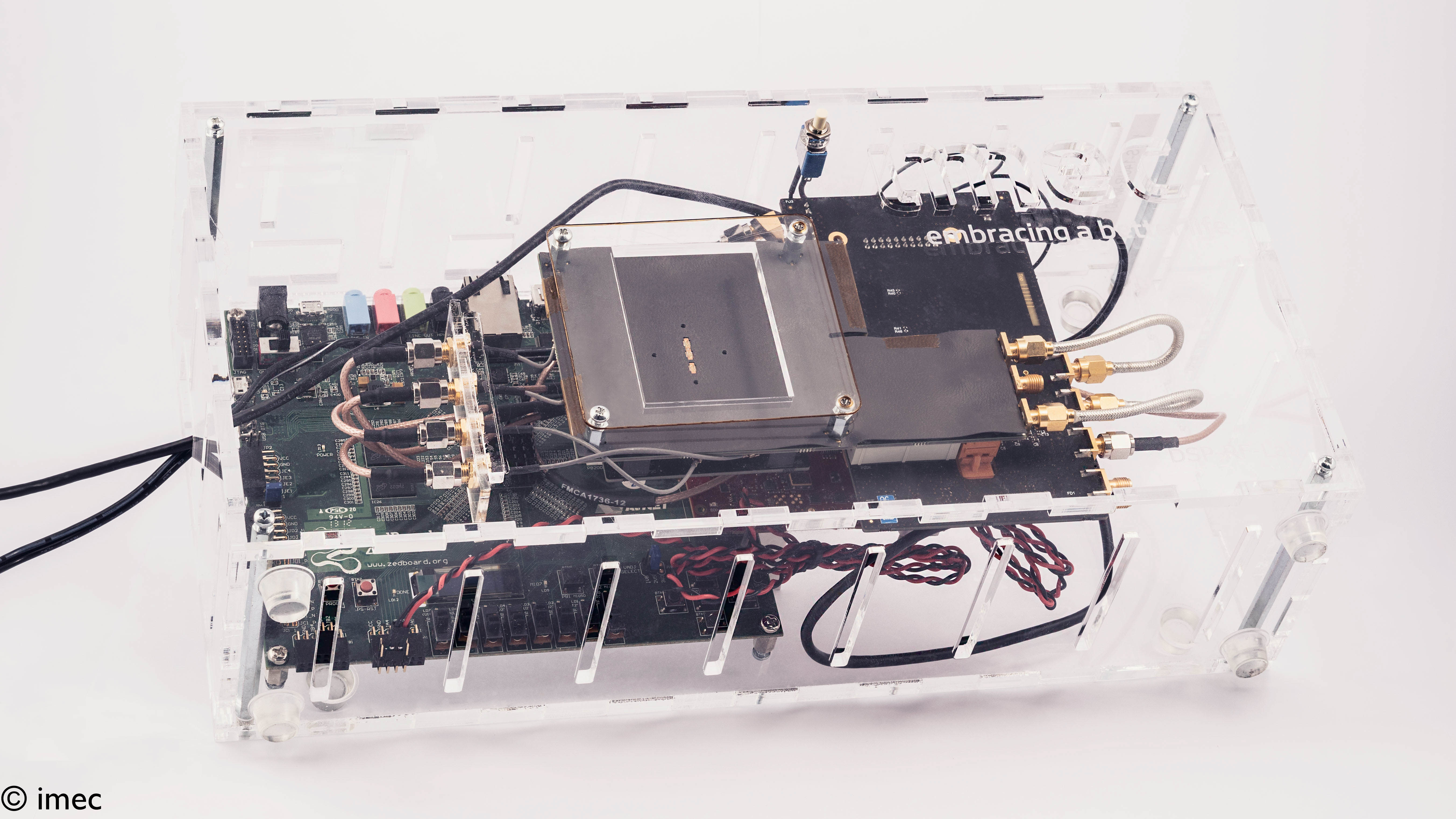
This week, at FutureSummits 2019, imec, a world-leading research and innovation hub in nanoelectronics and digital technologies, presents a compact highly-sensitive 140GHz MIMO (multiple-input multiple-output) radar system. The MIMO setup is demonstrated for gesture recognition, supporting intuitive man-machine interactions. In addition, the ultra-fine resolution of this radar allows the detection micro-skin movements related to vital signs serving applications like non-contact driver monitoring or patient monitoring.
Key differentiators of imec’s 140GHz radar-on-chip prototype system are its small size and high radar performance – in terms of resolution and motion sensitivity. The radar operates up to 10m range, with 15mm range resolution and 10GHz of RF bandwidth. Multiple antenna paths are incorporated to enable a complete (virtual) 1×4 MIMO configuration to achieve angular target separation. The transceiver chip features on-chip antennas, and are integrated in 28nm bulk CMOS technology, ensuring a low-cost solution at high volume production. These properties make the radar system particularly appealing for applications where high-precision, small-motion based detection is key.
By adding machine learning capabilities, imec has now demonstrated the feasibility of the radar to detect and classify small motions based on Doppler information.
“This opens new opportunities, for example, enabling gesture recognition for intuitive man-machine interactions”, adds Barend van Liempd, R&D manager at imec. “Think about the AR/VR space, where the new radar can support intuitive interaction with virtual objects. Gesture recognition can potentially also enable intuitive device control – complementary to existing interfaces such as voice control or smart touch screens.”
Being insensitive to lighting conditions and preserving privacy (a radar can so far not recognize humans), a radar solution has particular advantages over other types of motion sensors, for example time-of-flight-based infrared cameras. And, being extremely compact, imec’s 140GHz radar system can be integrated invisibly in almost every device, such as laptops, smartphones or screen bezels.
Imec has developed a specific machine learning algorithm based on a multi-layer neural network including an LSTM layer and using supervised learning to train the inference model by using in-house labeled recordings of more than 25 people, including several captures for each of 7 different gestures. Against the experimental dataset, the model classifies the recorded 7 gestures and predicts the right gesture at least 94% of the time.
Aside from gestures, vital signs can also be measured with very high precision thanks to the high radio frequency. Therefore, the radar is an excellent candidate for in-car vital sign monitoring systems, to enable non-contact tracking of the driver’s state, e.g. to detect falling asleep, abnormal stress levels or possibly to prevent accidents due to acute health hazards, e.g. heart or epilepsy attacks. Another possible application is to monitor small children using motion and vital signs detection, even when the infant is covered by a blanket and asleep, e.g. to provide an alert in case a child is unintentionally left in a vehicle.
To enlarge data richness and spatial information, imec is currently building a 4×4 MIMO radar system, for which a new generation of radar chips is under development – incorporating the TX and RX as separate chips. This will allow a greater flexibility in distributing the MIMO array elements across the available area. It will also be explored if the functionality of the standalone radar chips can be increased, to enable MIMO systems with even larger arrays of chips.
Imec’s 140GHz radar was developed in its open innovation R&D collaborative program on radar technology. Interested companies can partake in the program, or in a bilateral R&D project, or license the technology building blocks.
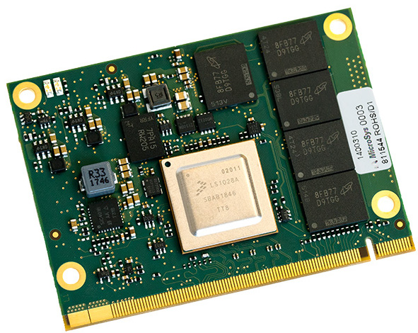
German-based MicroSys Electronics has begun a limited sampling of a miriac MPX-LS1028A compute module and a sandwich-style miriac SBC-LS1028A-TSN SBC that runs Linux or the real-time Microware OS‐9 distro on NXP’s QorIQ Layerscape LS1028A SoC. It also features 5x TSN-ready GbE ports, and support for up to 2x 10GbE SerDes lanes. The miriac boards emulate the only module using the single- or dual Cortex-A72 based LS1028A: Kontron’s SMARC-sAL28, which powers its KBox A-230-LS embedded computer.
The LS1028A clocks its one or two -A72 cores at up to 1.3GHz, and features support for the real-time IEEE 802.1 Time-Sensitive Networking (TSN), that provides guaranteed latency and Quality of Service (QoS) with time synchronization. The LS1028A is the only QorIQ SoC available right now with a 3D GPU, alternatively, MicroSys allows you to swap it for a headless LS1017 or LS1027 model to save cost. The device comes with built-in Crypto engines and a trust architecture. The standard Linux BSP utilizes Yocto Project code.
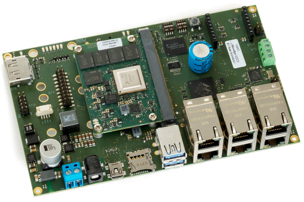
miriac SBC-LS1028A-TSN
The optional Microware OS-9 distribution which is promised in the third quarter of the year will take over from the OS-9 RTOS, which dates back to 1979. Microware (a collaboration between MicroSys, Freestation, and RTSI) has extended the PowerPC-compatible RTOS to support Arm-based QorIQ processors. MicroSys has dedicated itself to NXP development, offering Linux- and Microware OS-9 supported miriac modules and sandwich-style SBCs for a long period of years.
MicroSys’ miriac MPX-LS1028A module was announced earlier in January, and its sampling now, with general availability by July 1. No dimensions are listed for the module, which utilizes an MXM 2.0 edge connector. The module offers up to 4GB DDR4-1600, and includes ECC, up to 256MB NOR and up to 4GB NAND flash.
The miriac MPX-LS1028A utilizes the LS1028A’s networking abilities by enabling support for up to 5x TSN-capable GbE ports. You can also configure its 4x SerDes (Serializer/Deserializer) lanes for up to dual 10Gbps ports or other interfaces, which is configurable in four options:
2x PCIe 3.0 (2x x1 or 1x x2)
1x SATA 3.0
Up to 1x QSGMII and up to 1x SGMII
Up to 1x 10G-QXGMII and 1x 10G-SXGMII
I/O options via the MXM 2.0 connector includes 2x USB 3.0 host and USB 2.0 OTG, 2x UART, 2x CAN FD, 2x SPI, and 2x eSDHC, plus up to 6x SAI (audio) and up to 8x I2C. Single JTAG and RGMII, and also an additional GPIOs are available. It offers support for a DisplayPort or eDP interface, as well as an RTC and a temperature sensor. No operating range is listed for the 5V module or the SBC.
The 100 x 60mm miriac SBC-LS1028A-TSN expands simultaneously the miriac MPX-LS1028A module with 8GB eMMC and a microSD slot. For networking, the LS1028A-TSN features 5x TSN-ready Gigabit Ethernet ports and a sixth standard GbE, all enabling Power-over-Ethernet support. The SBC is also equipped with a pair of USB 3.0 ports, a DisplayPort, dual mini-PCIe slots, a mikroBus interface, and a host of features.
Specifications listed for the miriac SBC-LS1028A-TSN include:
Processor: (miriac MPX-LS1028A module) — NXP QorIQ Layerscape LS1028A (1x or 2x -A72 @ up to 1.3Gbps); 3D graphics GPU or optional headless models; crypto and trust
Memory/storage: Up to 4GB DDR4-1600, including ECC (via MPX-LS1028A), Up to 256MB NOR (via MPX-LS1028A), Up to 4GB NAND (via MPX-LS1028A), 8GB eMMC (bootable), MicroSD slot (bootable), mSATA via mini-PCIe
Networking: 5x TSN GbE ports, 1x standard GbE port, PoE (IEEE 1588) support, Up to 2x 10GbE potentially available via module’s SerDes support
Other I/O: DisplayPort, 2x USB 3.0 ports, Micro-USB 2.0 console interface, 2x CAN-FD, 2x JTAG, Fan connector
Expansion: 2x mini-PCIe slots (1x with mSATA support), MikroBus slot
Other features: RTC with battery; watchdog, LEDs, reset and boot switches
Power: 9-24V DC
Dimensions: 100 x 60mm
Operating system: Linux BSP (Yocto); Microware OS-9 (Q3); others available upon request
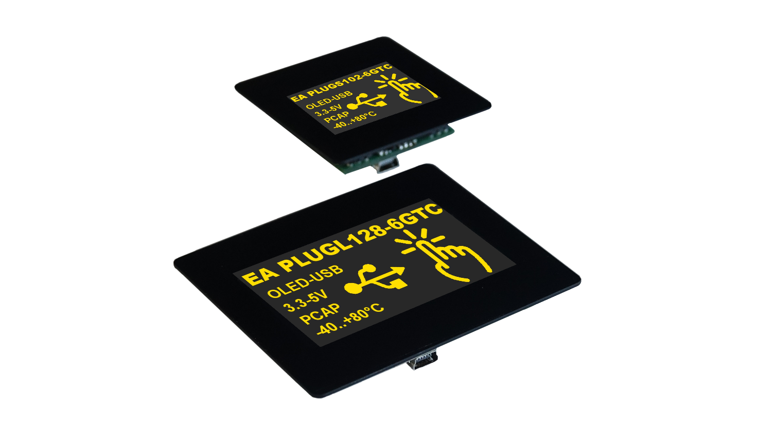
Especially for small monitoring and control tasks, the display specialist ELECTRONIC ASSEMBLY has developed a graphic OLED display with touch-sensitive front made of real glass.
The brand new EA PLUGS102-6 is not only a display, but also a full control unit featuring a wide range of interfaces. Its 36 x 25 mm display area offers a resolution of 102 x 64 pixels. Since every pixel in OLEDs represents a light source, this panel boasts unbeatably brilliant color, low black levels and strong contrasts compared to any LCD displays.
All these features are provided from any viewing angle at almost 180°, because OLEDs do not exhibit the LCD-typical weak contrast at oblique viewing angles. A separate backlight is not necessary. The display brightness can be adjusted by software. Automatic screen saver modes prevent the possible burn-in of static image content.
Thanks to the integrated USB interface, the OLED module can be quickly and easily put into operation. Just plug it in and the display will be automatically powered. The data transfer takes place serially, either via USB, SPI, RS232 or I2C connection.
For measurement and control tasks, the EA PLUGS102-6 is equipped with eight freely configurable digital I/O interfaces, two analog inputs and one PWM and one analog output. A small loudspeaker is also integrated.
The EA PLUGS102-6 recognizes high-level language-like graphics commands, which can be mastered even without any previous knowledge. In addition to eight integrated fonts, the display also features a number of sophisticated graphic functions. The time-consuming development of character sets and graphic routines is not necessary. Text and graphic elements can be mixed with each other at will, they can be positioned pixel-precisely and provided with blink attributes (on/off, inverse). Up to 256 images and the same number of macros can be stored in the internal memory.
The complete OLED module measures 55 x 54 x 15 mm. Its supply voltage, if not supplied via USB, may range from 3.3 to 5 V. If all pixels are enabled, it typically requires 137 mA or 97 mA. Its operating temperature ranges from -20 to 70 °C. For quick mounting, it is simply glued upright or crosswise into the front panel.
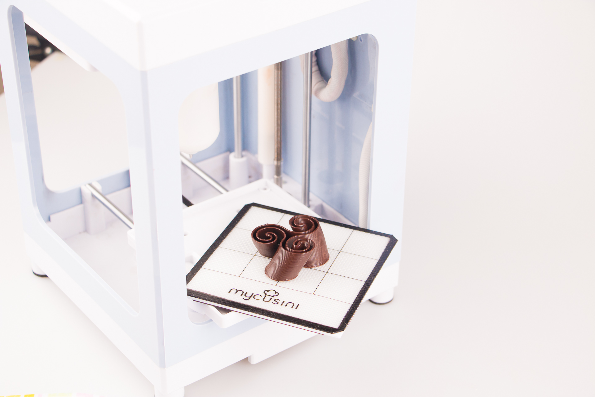
It’s not just another 3D printer – it is all about Choco, edible and incredibly fancy, if you make your own Choco objects with mycusini – the first consumer 3D Choco printer coming up on Kickstarter.
Create 3D Choco give-aways for your loved ones or the Choco highlight on your dessert. Easily filled with delicious mascarpone cream, a sauce and some nicely arranged fruits and you will challenge even a professional pastry chef.
Who’s behind mycusini? It is the German startup Print2Taste. The team has proven to be successful on Kickstarter already in 2015 with world’s first plug & play 3D food printer.
In terms of production quality and speed there is no difference to professional 3D food printers for 2.000 € and above says Eva Schlosser, “mom of mycusini” at Print2Taste.
According to Schlosser, the team invested more than 3 years in the development of mycusini. Every detail is optimized to the needs of consumers. Starting with the outer dimensions, positioning, production platform, cartridge up to the specially developed extruder with quick release. The mycusini is reduced to the max, with only 19 x 19,5 x 27 cm it is smaller than most coffee machines and fits into every kitchen. The compact size also explains the attractive price.
The mycusini is powered by special 3D Choco refills provided by Print2Taste – success guaranteed. With the mycusini premium, also available on Kickstarter, wireless 3D Choco printing up to 2 hours will be possible for the first time, independent where you are or what you do.
Easy-to-make text messages even via smart device, free access to a huge template library with more than 100 creative objects and easy operation will ensure a maximum fun factor. Starting at 198 €, mycusini is also perfect as a gift. With the mycusini special deal, (guaranteed shipping till Christmas or backers may ask for refund) mycusini might be the hottie under your Christmas tree 2019.
According to Print2Taste the team thought a lot about how to be able to fulfill in time. Finally, with a heavy heart, they decided to limit the maximum number of available mycusini. Therefore, set your calendar alarm! The official starting point of the Kickstarter campaign is the 4th of June, 10:30 am German time (just follow the countdown on mycusini.com).
(11/06/2019 Update) The project is now live on kickstarter and has 27 days to go.
AAEON, an award winning developer of embedded AI solutions, is partnering with a leading developer of edge AI solutions, Gorilla Technology Group, to showcase the capabilities of edge AI computing. As part of AAEON’s series of live demos, the AIOT-AIVD AI Gateway with Intel® Movidius™ Myriad™ X will feature IVAR™ from Gorilla, an OpenVINO™ optimized facial recognition software.
Dr. Spincer Koh of Gorilla Technology Group recently discussed the technology and partnership between Gorilla and AAEON:
“We at Gorilla Technology Group are very excited to partner with AAEON at this year’s COMPUTEX in order to showcase the latest in facial recognition technology and behavior analytics. Both Gorilla and AAEON are looking to expand the applications of the cutting-edge UP Squared AI Vision Development Kit and to advance the work of AI developers into more real-life solutions. Gorilla has been at the forefront of video IoT with our real-time edge AI solution, IVAR™ (Intelligent Video Analytics Recorder). IVAR™ has already delivered on a number of successful real-world scenarios: verifying VIP guests for hospitality and retail, creating watch lists for criminal investigations, and also permitting access to high-security locations.
“In our demonstration together, Gorilla pairs our IVAR™ facial recognition technology with AAEON’s leading hardware systems to register staff and apply deep learning analytics to recognize each person as they arrive—by name, title, age, gender and even clothing color. We hope that this collaboration between Gorilla and AAEON is just the beginning in a long line of successful endeavors together. “
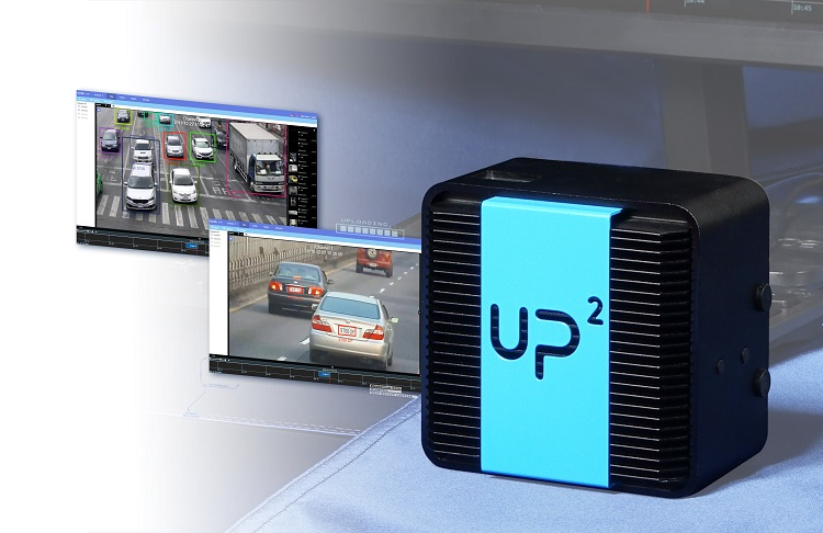
The AIOT-AIVD AI Gateway is a compact edge AI system combining the flexible and innovative UP Squared board with the powerful Intel® Movidius™ Myriad™ X. The UP Squared board pairs support for Intel processors, such as the Intel® Pentium™ N4200 (formerly Apollo Lake), with up to 8 GB of LPDDR4 memory and eMMC storage up to 128 GB. The Intel® Movidius™ Myriad™ X is a low-power high-performance neural accelerator and VPU capable of speeds up to 105 fps (80 typical). With the UP Squared and Intel® Myriad™ X together, the AIOT-AIVD AI Gateway is one of the fastest and highest performing compact embedded edge AI systems available.
To see our live demonstration of the AIOT-AIVD AI Gateway with IVAR™ from Gorilla, come visit our display at COMPUTEX Taipei 2019, being held at the Taipei Nangang Exhibition Center May 28th through June 1st. AAEON will be at Booth S0703 on the 4th Floor of Hall 2. We look forward to seeing you there.