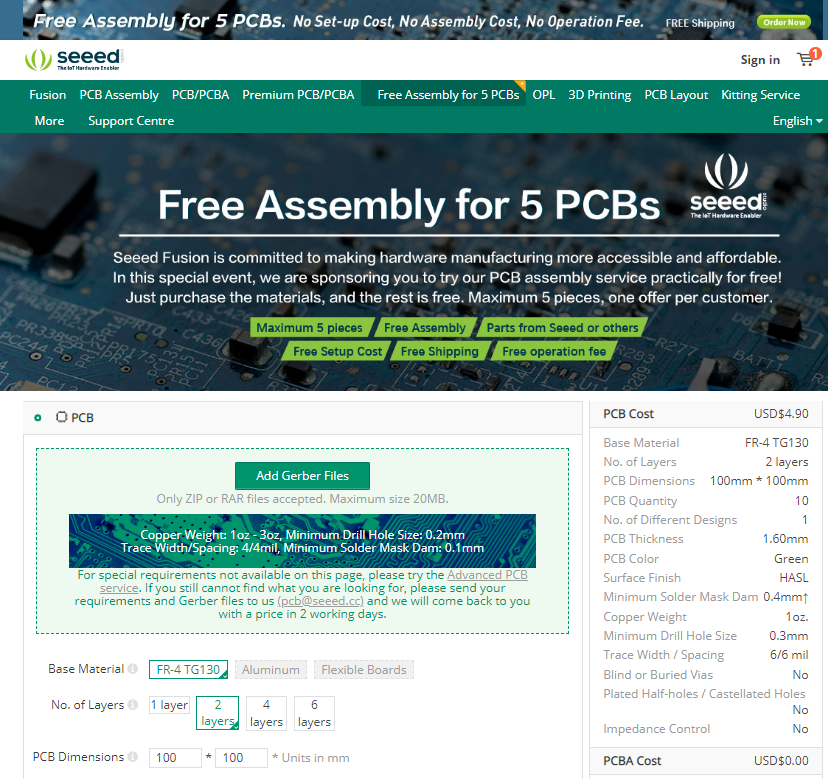
To the ire of many, manufacturing in small quantities have often led to sky high prices, hindering many makers from translating their ideas to reality. Now, to eliminate cost barriers and enable even more makers to experience the flexibility and convenience of turnkey PCB fabrication and assembly, Seeed Fusion is waiving off the assembly costs for the Seeed Fusion One-stop PCB Assembly (PCBA) service for five pieces.
When assembling a device on their own, makers have to go through the process of sourcing for components, creating homemade PCBs, and soldering each component by hand. Very often, unexpected problems arise. Delays begin to mount and this leads to slow delivery of products and missed launch dates.
Since the beginning of Seeed Studio, the Seeed Fusion PCBA Service has always had the goal of helping makers around the world skip the hassle of turning Gerbers and BOMs into the complete physical device. It enables rapid prototyping at affordable prices, and has since developed into the cornerstone of the Seeed Fusion service.
Parts can be sourced from major Global distributors such as Digikey, Mouser and others. But since Seeed is located in Shenzhen, the product innovation and electronics manufacturing juggernaut, Seeed’s close proximity to electronic component suppliers enables it to rapidly source the necessary components from local distributors, reducing the lead time to just 7 working days if all components are sourced locally from the Seeed Open Parts Library, which has swelled to more than 15,000 locally available parts. To begin the ordering process, customers are required to upload their PCB Gerber files and BOM files onto the online order webpage, and a complete quote will be generated in seconds. As part of Seeed’s efforts to make the Fusion PCBA service affordable, all PCBA orders are entitled to free express shipping to anywhere in the world.
Now, Seeed is going further by slashing the assembly, operation and set-up costs for orders up to 5 pieces of PCBA. This means that customers only need to pay for the materials and components needed, and Seeed Fusion will assemble the boards free of charge. Most orders will be able to enjoy cost savings of about 80% of the usual price. For example, assembling 5 Seeeduino boards would usually cost over $400. However, this offer would reduce the price tag to a mere $50.
With the Free Assembly for 5 PCBs offer, along with its previous Seeed Fusion promotions, Seeed is demonstrating that cost need not be a stumbling block when it comes to electronics projects. To those new to the Seeed Fusion PCBA service, this offer also presents a great opportunity to try it out. Navigate to the dedicated offer page to experience the convenience of Seeed’s Fusion PCBA service. The offer is only available once per customer.
One of the most interesting project we can build while learning to work with a WiFi Based board is a web Server. As we continue the journey to learn how to build projects with the ESP32, we will examine how to build a simple web Server with the ESP32.
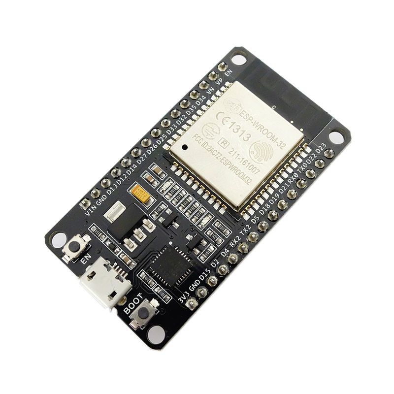
DOIT ESP32 DevKit
A Web server is essentially a device which stores, processes and delivers web pages to web clients, which can range from browsers on our laptops to Mobile apps on our smartphones. The communication between client and server takes place using a special protocol called Hypertext Transfer Protocol (HTTP). The client uses an URL to make a request for a particular page and the server responds with the content of that web page or an error message if the page is not available.
In our case, rather than responding with a specific webpage, the URL will be used to control the state of LEDs connected to the ESP and the changes made will be updated on the webpage. For instance, if a URL like “http://192.168.1.1/ledon” is entered in the browser, the web server will understand its time to turn the LED “ON” and then update the status of the LED to “ON” on the webpage. Same thing will happen when it’s required to go “OFF”.
At the end of today’s tutorial, you would know how to set up a web server on the ESP32 and connect to it via a client (Webpage) to control its GPIO pins.
Required Components
The following components are required for this project:
DOIT ESP32 DEVKIT V1
220 ohms Resistor (2)
LED (2)
Breadboard
Jumper Wire
The DOIT Devkit V1 ESP32 board is used for this tutorial due to its obvious popularity among makers. Feel free to use any of the other ESP32 based boards for the project.
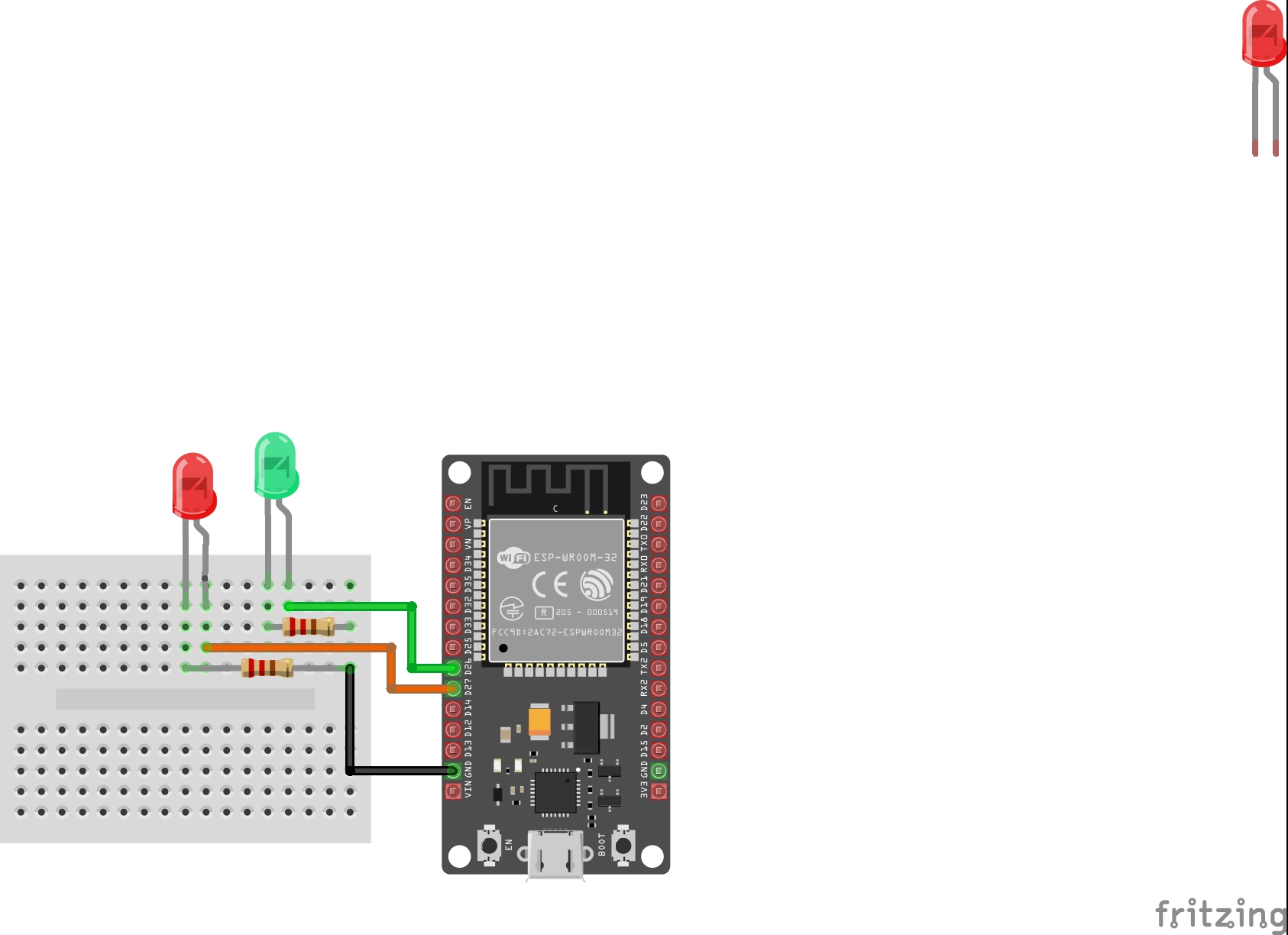
Schematics
The schematics for this tutorial is quite simple. As mentioned earlier, we will toggle LEDs to demonstrate what can be achieved using the NodeMCU Web server and while LEDs are being used here, you can decide to use more useful components like a relay, which could give you the ability to remotely control appliances in your home. Connect the components as shown below.
Schematics
The positive legs of the green and red LEDs are connected t0 GPIO pins 26 and 27 on the ESP32 (respectively), while their negative legs are connected to ground via a 220 ohms resistor to limit the amount of current flowing through the LEDs.
With the schematics done, we can now move to the code for the project.
Code
We will use the Arduino IDE to develop the sketch for today’s project due to its versatility, huge support, and popularity. To be able to do this, you need to install the ESP32 board support files on the Arduino IDE. We covered this in the ESP32 introduction tutorial that was published a few weeks back, so be sure to check it out.
The sketch for this tutorial is fairly easy. The algorithm involves us connecting the ESP32 to an access point and generating an IP address through which devices connected to the ESP can access the web server. The client (a webpage running on connected devices), in connection to the server, is serving a webpage that has buttons to control the LEDs and a function is placed behind the buttons to handle the actions that occur when they are clicked.
To reduce the amount of code we need to write, we will use the ESP32 WiFi Library. The library contains functions that make setting up the ESP32 as a web server easy. The library, along with several others, is packaged together with the ESP32 board files and are automatically installed when the ESP32 board files are installed on the Arduino IDE.
The code is an adaptation of the code for a similar Project by Rui Santos and an old ESP8266 webserver tutorial we wrote. You can check that out for better understanding.
To do a brief explanation, we start as usual, by including the library required for the project, which in this case, is just the WiFi.h library.
#include <WiFi.h>
Next, add the credentials of the WiFi access point to which the ESP32 will be connected. Ensure the username and password are in-between the double quotes. We also specify the port through which the system will communicate and create a variable to hold requests.
// Replace with your network credentials
const char* ssid     = "Enter_SSID_here";
const char* password = "Enter_Password_here";

// Set web server port number to 80
WiFiServer server(80);

// Variable to store the HTTP request
String header;
Next, we declare the pins of the ESP32 to which the red and green LED are connected and create variables to hold the state of the LEDs.
int greenled = 26;
int redled = 27;

String greenstate = "off";// state of green LED
String redstate = "off";// state of red LED
With this done, we move to the void setup() function.
We start by initializing the serial monitor (it will be used for debugging later) and set the pinModes of the pins to which the LEDs are connected as outputs. We then set the pins “LOW” to ensure the system starts at a neutral state.
void setup() {
  Serial.begin(115200);
 // Set the pinmode of the pins to which the LEDs are connected and turn them low to prevent flunctuations
  pinMode(greenled, OUTPUT);
  pinMode(redled, OUTPUT);
  digitalWrite(greenled, LOW);
  digitalWrite(redled, LOW);
Next, we connect to the access point using the credentials as arguments to the WiFi.begin() function and the WiFi.status() function to check if connection was successful.
WiFi.begin(ssid, password);
Serial.print("Connecting to ");
Serial.println(ssid);
while (WiFi.status() != WL_CONNECTED) {
  delay(500);
  Serial.print(".");
}
If the connection is successful, a text is printed on the serial monitor to indicate that, and the IP address of the web server is also displayed. This IP address becomes the web address for the server and it is what we need to enter on any web browser on the same network to access the Server.
Serial.println("");
Serial.println("WiFi connected.");
Serial.println("IP address: ");
Serial.println(WiFi.localIP());// this will display the Ip address of the Pi which should be entered into your browser
With that done, we start the server using the server.begin() function and proceed to the void loop( ) function.
server.begin();
The void loop() function is where the majority of the work is done. We start by using the server.available() function to listen for incoming connection by clients. When a client is available and connected, we read the client request and send a header as a response.
WiFiClient client = server.available();   // Listen for incoming clients

  if (client) {                             // If a new client connects,
    String currentLine = "";                // make a String to hold incoming data from the client
    while (client.connected()) {            // loop while the client's connected
      if (client.available()) {             // if there's bytes to read from the client,
        char c = client.read();             // read a byte, then
        Serial.write(c);                    // print it out the serial monitor
        header += c;
        if (c == '\n') {                    // if the byte is a newline character
          // if the current line is blank, you got two newline characters in a row.
          // that's the end of the client HTTP request, so send a response:
          if (currentLine.length() == 0) {
            // HTTP headers always start with a response code (e.g. HTTP/1.1 200 OK)
            // and a content-type so the client knows what's coming, then a blank line:
            client.println("HTTP/1.1 200 OK");
            client.println("Content-type:text/html");
            client.println("Connection: close");
            client.println();
Next, we check if the client’s request indicates a button press to turn any of the pins “ON/OFF” starting with the green LED. If the request indicates “ON”, the pin is turned high and the state variable is updated accordingly and vice versa.
// turns the GPIOs on and off
           if (header.indexOf("GET /green/on") >= 0) {
             Serial.println("green on");
             greenstate = "on";
             digitalWrite(greenled, HIGH);
           } else if (header.indexOf("GET /green/off") >= 0) {
             Serial.println("green off");
             greenstate = "off";
             digitalWrite(greenled, LOW);
           } else if (header.indexOf("GET /red/on") >= 0) {
             Serial.println("red on");
             redstate = "on";
             digitalWrite(redled, HIGH);
           } else if (header.indexOf("GET /red/off") >= 0) {
             Serial.println("red off");
             redstate = "off";
             digitalWrite(redled, LOW);
           }
Next, we create the webpage that will be displayed and updated by the NodeMCU as the user interacts with it. The key function for this is the Client.println() function which is used to send HTML scripts line by line to the client (browser).
We start by using the “doctype” to indicate that the next few texts to be printed are HTML lines.
client.println("<!DOCTYPE html><html>");
Next, we add the lines below to make webpage responsive irrespective of the browser being used.
Next, the webpage header is sent alongside the buttons which are set to display ON or OFF based on the current state of the LEDs. It will display OFF if the current state is ON and vice versa.
client.println("<body><h1>ESP32 Web Server</h1>");
// Display current state, and ON/OFF buttons for green LED
client.println("<p>green - State " + greenstate + "</p>");
// If the green LED is off, it displays the ON button
if (greenstate == "off") {
client.println("<p><a href=\"/green/on\"><button class=\"button\">ON</button></a></p>");
} else {
client.println("<p><a href=\"/green/off\"><button class=\"button button2\">OFF</button></a></p>");
}
// Display current state, and ON/OFF buttons for Red LED
client.println("<p>red - State " + redstate + "</p>");
// If the red LED is off, it displays the ON button
if (redstate == "off") {
client.println("<p><a href=\"/red/on\"><button class=\"button\">ON</button></a></p>");
} else {
client.println("<p><a href=\"/red/off\"><button class=\"button button2\">OFF</button></a></p>");
}
client.println("</body></html>");
Next, we close the connection and the loop goes over again.
// Clear the header variable
header = "";
// Close the connection
client.stop();
Serial.println("Client disconnected.");
Serial.println("");
The complete code for the project is available below and under the download section of this tutorial.
#include <WiFi.h>
// Replace with your network credentials
const char* ssid = "Enter_SSID_here";
const char* password = "Enter_Password_here";
// Set web server port number to 80
WiFiServer server(80);
// Variable to store the HTTP request String header;
String header;
// Declare the pins to which the LEDs are connected
int greenled = 26;
int redled = 27;
String greenstate = "off";// state of green LED
String redstate = "off";// state of red LED
void setup() {
Serial.begin(115200);
// Set the pinmode of the pins to which the LEDs are connected and turn them low to prevent flunctuations
pinMode(greenled, OUTPUT);
pinMode(redled, OUTPUT);
digitalWrite(greenled, LOW);
digitalWrite(redled, LOW);
//connect to access point
WiFi.begin(ssid, password);
Serial.print("Connecting to ");
Serial.println(ssid);
while (WiFi.status() != WL_CONNECTED) {
delay(500);
Serial.print(".");
}
// Print local IP address and start web server
Serial.println("");
Serial.println("WiFi connected.");
Serial.println("IP address: ");
Serial.println(WiFi.localIP());// this will display the Ip address of the Pi which should be entered into your browser
server.begin();
}
void loop(){
WiFiClient client = server.available(); // Listen for incoming clients
if (client) { // If a new client connects,
String currentLine = ""; // make a String to hold incoming data from the client
while (client.connected()) { // loop while the client's connected
if (client.available()) { // if there's bytes to read from the client,
char c = client.read(); // read a byte, then
Serial.write(c); // print it out the serial monitor
header += c;
if (c == '\n') { // if the byte is a newline character
// if the current line is blank, you got two newline characters in a row.
// that's the end of the client HTTP request, so send a response:
if (currentLine.length() == 0) {
// HTTP headers always start with a response code (e.g. HTTP/1.1 200 OK)
// and a content-type so the client knows what's coming, then a blank line:
client.println("HTTP/1.1 200 OK");
client.println("Content-type:text/html");
client.println("Connection: close");
client.println();
// turns the GPIOs on and off
if (header.indexOf("GET /green/on") >= 0) {
Serial.println("green on");
greenstate = "on";
digitalWrite(greenled, HIGH);
} else if (header.indexOf("GET /green/off") >= 0) {
Serial.println("green off");
greenstate = "off";
digitalWrite(greenled, LOW);
} else if (header.indexOf("GET /red/on") >= 0) {
Serial.println("red on");
redstate = "on";
digitalWrite(redled, HIGH);
} else if (header.indexOf("GET /red/off") >= 0) {
Serial.println("red off");
redstate = "off";
digitalWrite(redled, LOW);
}
// Display the HTML web page
client.println("<!DOCTYPE html><html>");
client.println("<head><meta name=\"viewport\" content=\"width=device-width, initial-scale=1\">");
client.println("<link rel=\"icon\" href=\"data:,\">");
// CSS to style the on/off buttons
// Feel free to change the background-color and font-size attributes to fit your preferences
client.println("<style>html { font-family: Helvetica; display: inline-block; margin: 0px auto; text-align: center;}");
client.println(".button { background-color: #195B6A; border: none; color: white; padding: 16px 40px;");
client.println("text-decoration: none; font-size: 30px; margin: 2px; cursor: pointer;}");
client.println(".button2 {background-color: #77878A;}</style></head>");
// Web Page Heading
client.println("<body><h1>ESP8266 Web Server</h1>");
// Display current state, and ON/OFF buttons for GPIO 26
client.println("<p>green - State " + greenstate + "</p>");
// If the green LED is off, it displays the ON button
if (greenstate == "off") {
client.println("<p><a href=\"/green/on\"><button class=\"button\">ON</button></a></p>");
} else {
client.println("<p><a href=\"/green/off\"><button class=\"button button2\">OFF</button></a></p>");
}
// Display current state, and ON/OFF buttons for GPIO 27
client.println("<p>red - State " + redstate + "</p>");
// If the red LED is off, it displays the ON button
if (redstate == "off") {
client.println("<p><a href=\"/red/on\"><button class=\"button\">ON</button></a></p>");
} else {
client.println("<p><a href=\"/red/off\"><button class=\"button button2\">OFF</button></a></p>");
}
client.println("</body></html>");
// The HTTP response ends with another blank line
client.println();
// Break out of the while loop
break;
} else { // if you got a newline, then clear currentLine
currentLine = "";
}
} else if (c != '\r') { // if you got anything else but a carriage return character,
currentLine += c; // add it to the end of the currentLine
}
}
}
// Clear the header variable
header = "";
// Close the connection
client.stop();
Serial.println("Client disconnected.");
Serial.println("");
}
}
Demo
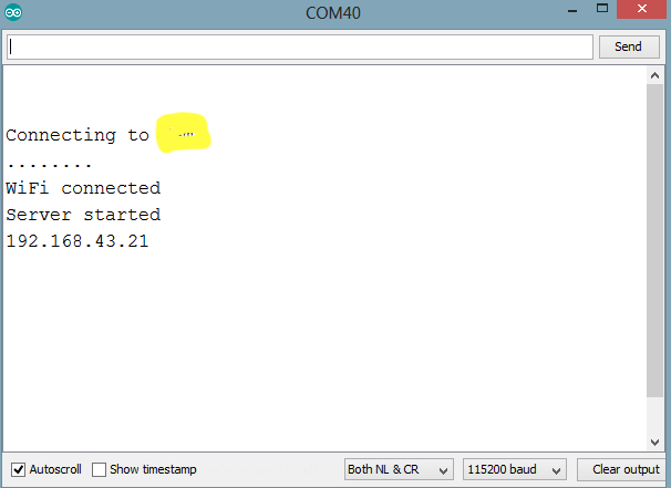
Connect the DOIT ESP32 Devkit to your computer, ensure it is selected as the board type on the Arduino IDE, then paste the code in the IDE, verify and upload. When the upload is finished open the serial monitor. You should see the IP address displayed as shown in the Image below.
IP Address
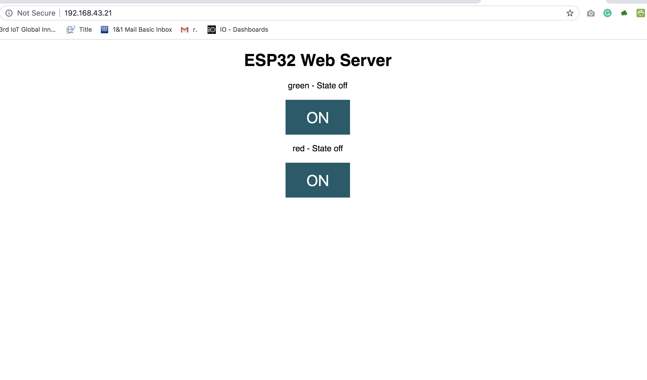
Connect a device (mobile phone or PC) to the same network as the ESP32, then open a web browser on that device and enter the IP address from the serial monitor in the Address bar. It should open the webpage we created on the web server as shown in the Image below. Click on the buttons to toggle the LEDs.
Webpage served to client
As mentioned earlier, in place of the LEDs, relays or any other kind of actuator could be connected to make the project more useful. Feel free to reach out to me via the comment section if you have any question on the tutorials.
Avnet Integrated Presents Scalable, Cost-Efficient SMARC 2.0 Module Family with i.MX 8M Mini Processors from NXP
Avnet Integrated presents a new, cost-efficient MSC SM2S-IMX8MINI SMARC 2.0™ module, which is based on i.MX 8M Mini processors from NXP™. The multicore ARM® Cortex-A53 processors are built using NXP’s 14nm FinFET process technology, providing high compute performance at very low power consumption. With the standardized MSC SM2S-IMX8MINI compact SMARC 2.0™ module family and the appropriate starter kit, the new processor technology is easily and quickly available for innovative customer applications. The extremely versatile module family may be used in any general purpose industrial, IoT, building automation and media streaming application.
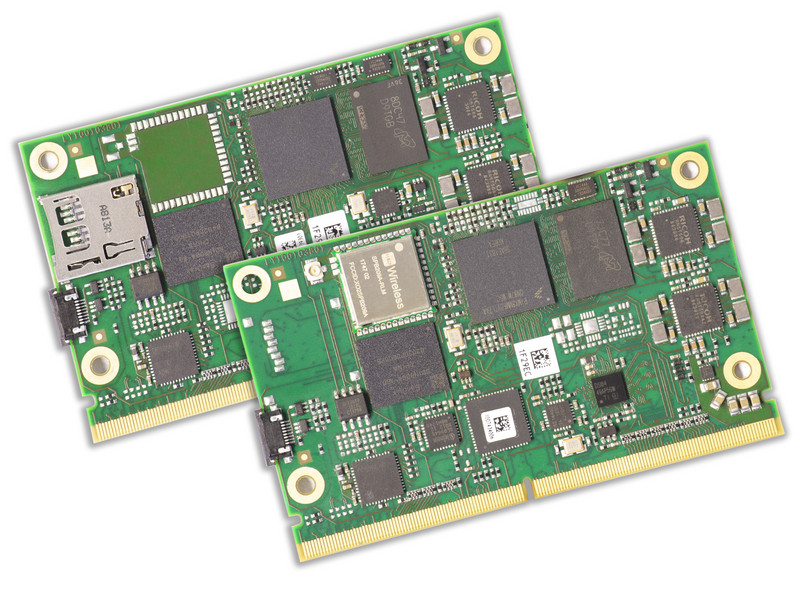
The MSC SM2S-IMX8MINI SMARC 2.0 module features high scalability and can be equipped with different single-, dual- or quad-core processor types. The flexibility of the new module family is comparable to the scalability of the i.MX 6 predecessor products. However, these modules offer significantly higher compute performance due to 64-bit support and fast LPDDR4 memory. The SM2S-IMX8MINI modules are designed not only for the new Mini processors, but also for the future pin-compatible Nano processors from NXP.
The new Computer-On-Modules (COMs), based on NXP’s powerful i.MX 8 processor family ‒ consisting of the i.MX 8, i.MX 8M and i.MX 8M Mini variants ‒ are suitable for embedded applications that requirethe highest degree of performance combined with high energy efficiency. Avnet Integrated will offer the complete i.MX 8 processor family on the persistent and future-proof SMARC 2.0™ and Qseven™ module form factors and further strengthen its leading position as a manufacturer of innovative embedded modules. In addition to providing hardware manufactured in Germany, extensive development tools such as starter kits and board support packages as well as personalized services including design-in support and carrier design review are offered.
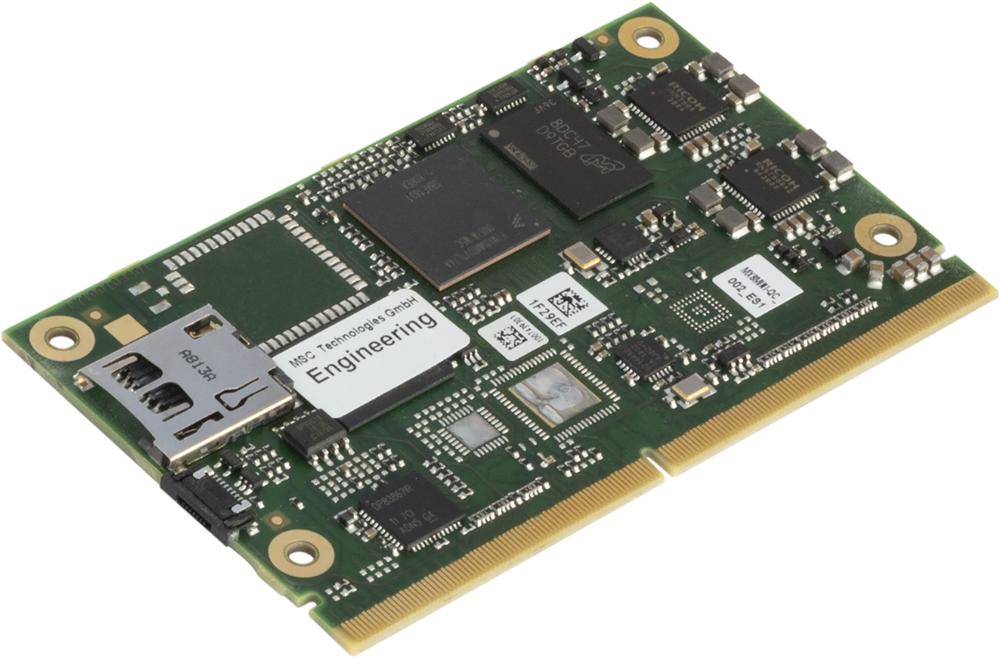
MSC SM2S-IMX8MINI
The MSC SM2S-IMX8MINI module features NXP’s i.MX 8M Mini processors that are based on latest 14nm FinFET technology to allow high computing and graphics performance at very low power consumption combined with a high degree of functional integration.
MSC SM2S-IMX8MINI offers single-, dual- or quad-core ARM Cortex-A53 processors in combination with the ARM Cortex-M4 real-time processor and GC NanoUltra multimedia 2D/3D GPU. It provides fast LPDDR4 memory, up to 64GB eMMC Flash memory, Gigabit Ethernet, PCI Express, USB 2.0, an on-board Wireless Module as well as an extensive set of interfaces for embedded applications.
The module is compliant with the new SMARC™ 2.0 standard, allowing easy integration with SMARC baseboards. For evaluation and design-in of the SM2S-IMX8MINI module, MSC provides a development platform and a starter kit. Support for Linux is available (Android support on request).
Highlights
Single, Dual or Quad core ARM Cortex-A53 Applications Processor up to 1.8GHz
ARM Cortex-M4 Real Time Processor at 400MHz
Vivante GC NanoUltra 2D/3D Graphics Processor
1080p60 H.265 decode, 1080p60 H.264 encode (VPU not available on ”Mini Lite“)
Up to 4GB LPDDR4 SDRAM
Up to 64GB eMMC Flash
Dual-channel LVDS / Dual MIPI-DSI x4 (optional)
MIPI CSI-2 Camera Interface
PCI Express x1 Gen. 2
4x USB 2.0 Host interface
1x USB 2.0 Host/Device interface
Up to 2x Gigabit Ethernet
Wireless Module (optional)
Micro SD Card Socket (optional)
MMC/SD/SDIO interface
2x CAN interface (optional)
2x I2S Audio Interface
UART, SPI, I2C
SMARC 2.0 Compliant
No pricing or availability information was provided for the MSC SM2S-IMX8MINI. More information may be found in Avnet’s announcement and product page.
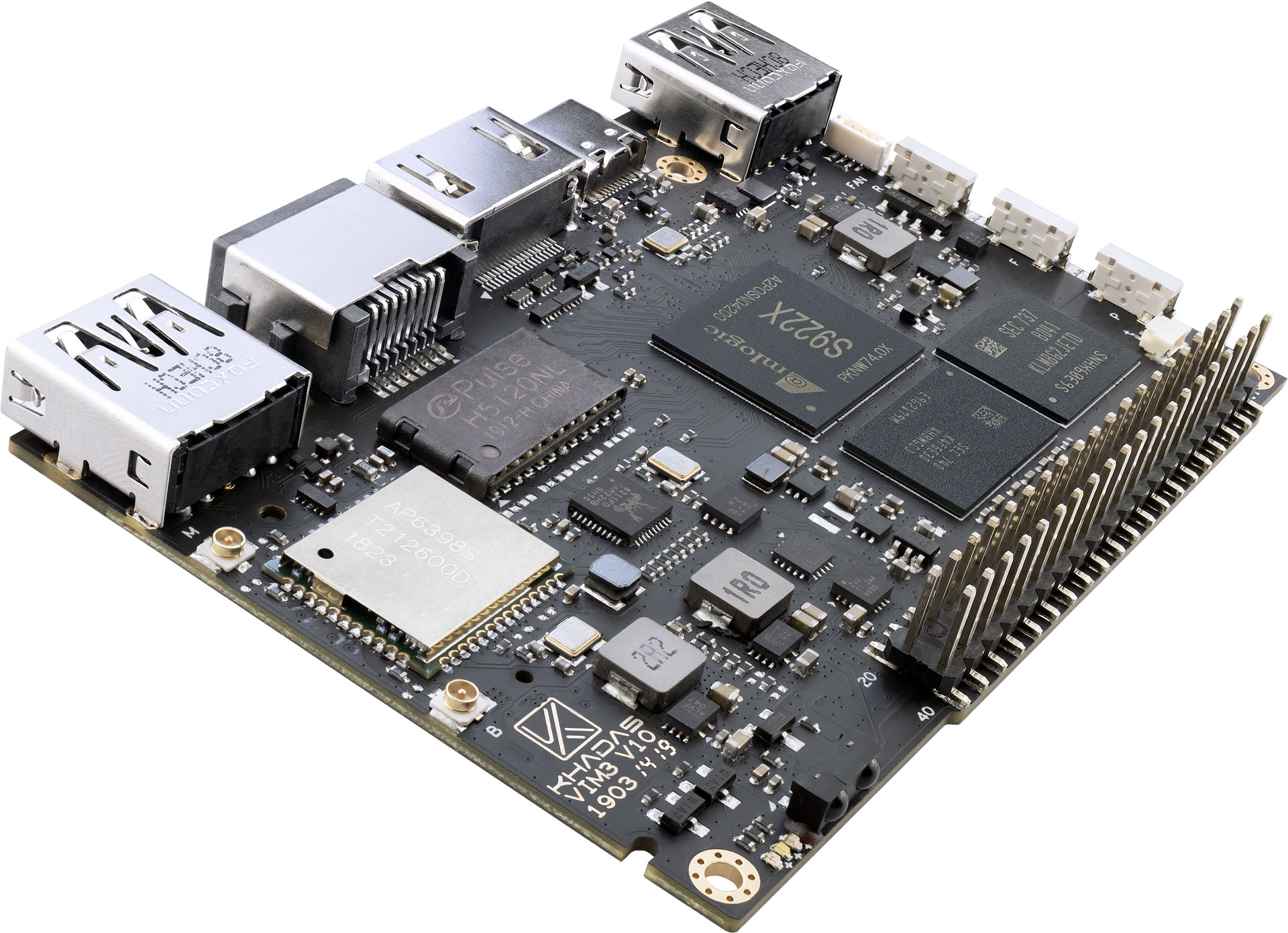
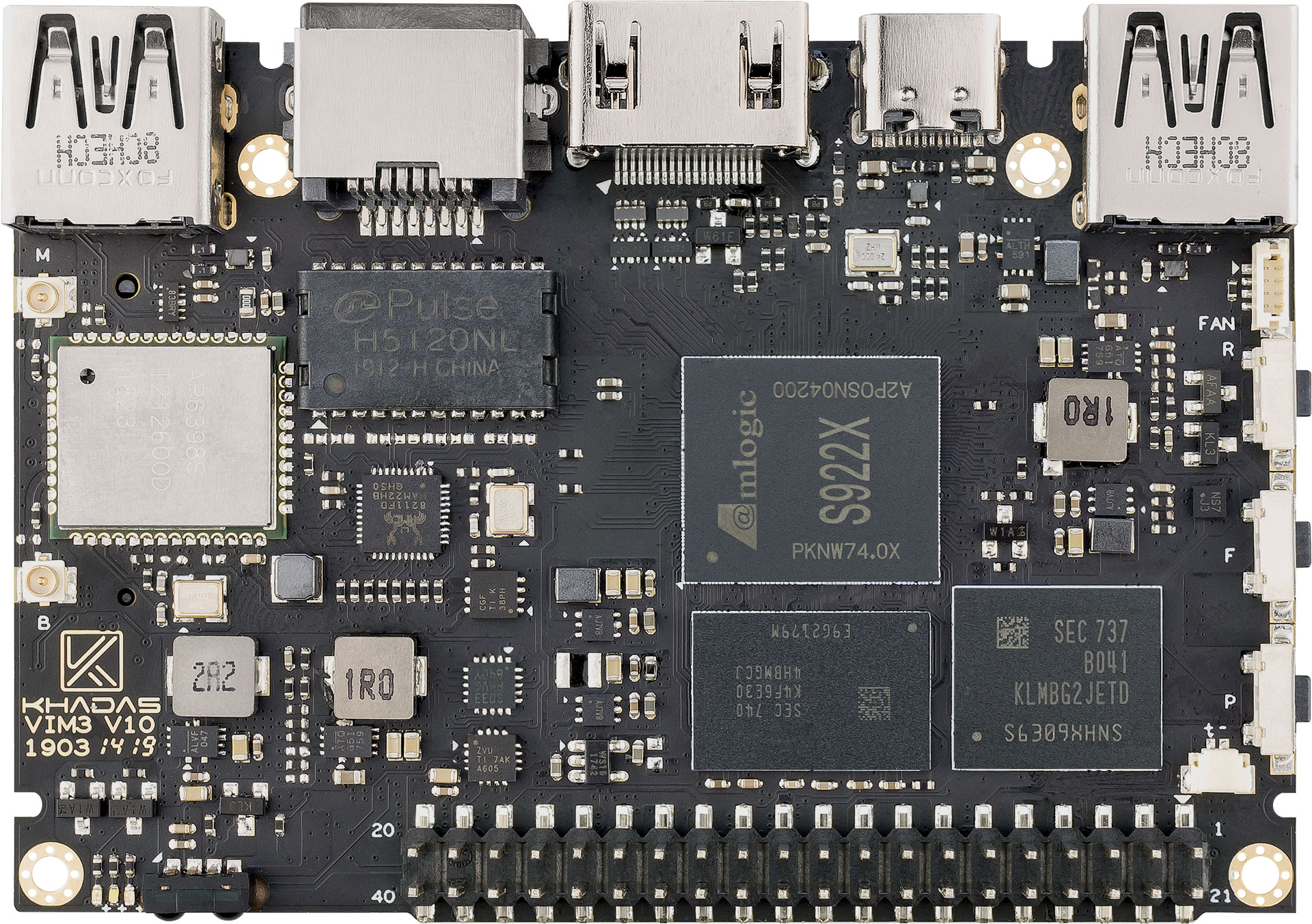
The VIM3 SBC is the latest iteration of the popular Khadas VIM series, that will be equipped with the new Amlogic S922X SoC. It is designed with the same form-factor as our popular VIM2 and VIM1, with up to 4GB of LPDDR4/4X RAM and 32GB of EMMC storage; this makes it compatible with existing accessories.
SoC – Amlogic S922X hexa-core processor with 4x Arm Cortex-A73 and 2x Cortex A53 cores, Arm Mali-G52 MP4 GPU, built-in Cortex-M4 core for “always-on” processing
MCU – STMicro STM8S003 with Programmable EEPROM for power management, customizations, and boot media configuration
Misc – 2x IR receivers, RTC & battery header, 4-pin cooling fan header with PWM speed control, 3x LED’s, power, Func and reset buttons, XPWR pads for an external power button
Power Supply – 5V to 20V via USB-C port or pogo pads
Dimensions – 82.0 x 58.0 x 11.5 mm (4x M2 mounting holes)
Weight – Around 30 grams
Certifications – CE, RoHS
Khadas VIM3 comes with some extra features compared to ODROID-N2 including built-in eMMC storage (instead of external flash), an M.2 socket supporting NVMe SSD, built-in WiFi and Bluetooth, a MIPI-DSI connector, and a few other features like an accelerometer and larger SPI flash. VIM3 is also quite smaller compared to ODROID-N2.
Khadas VIM3 is coming soon, and pricing has not been announced yet. More details may be found in the “launch page“
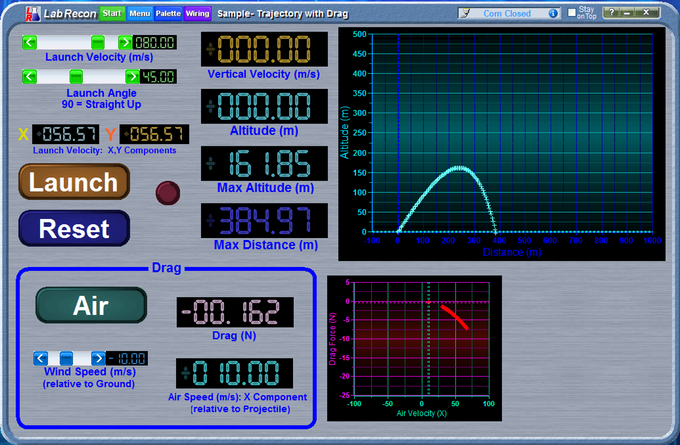
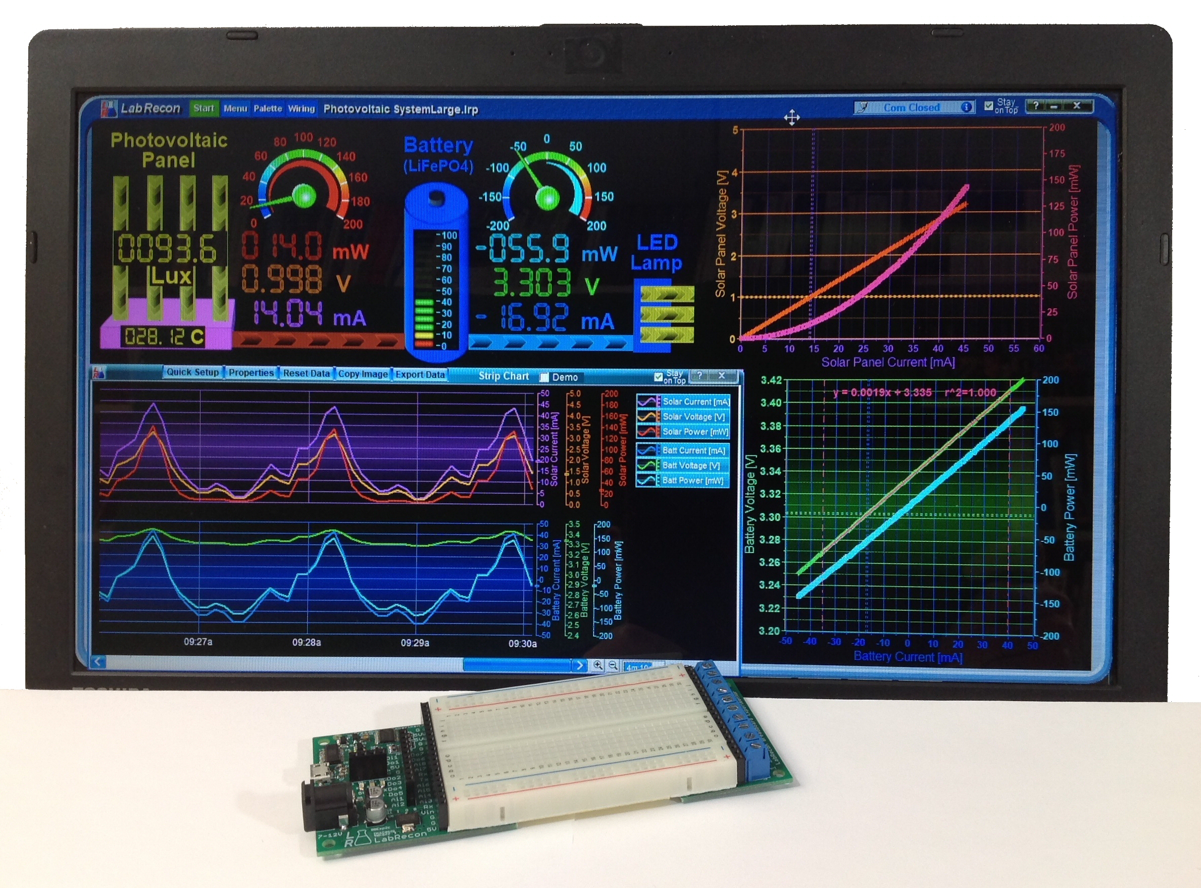
LabRecon allows one to build rich graphical interfaces for “remote” IoT (Internet of Things) or “local” measurement and control applications. A drag-and-drop panel builder and graphical “Wiring” programming environment allows one to easily build an interface and create the operating logic for any project. This operating logic can be further expanded using the “code link” interface to text based languages such as Python, Java, C#, Visual Basic, etc. A USB connected “Breadboard Experimentor” circuit board or LabRecon chip provides the measurement and control link.
One powerful feature is the “Measurement Wizard”, wherein one can choose from a built-in database of over 500 commercially available sensors to automatically configure sensor configurations. The wizard will further present circuits with component values for voltage and current measurements.
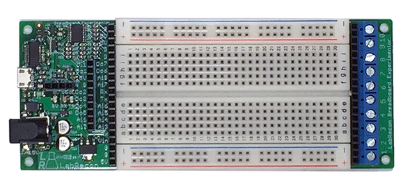
LabRecon Breadboard Experimentor
The “Breadboard Experimentor” includes an on-board LabRecon chip, which provides many I/O options including 8 12-bit analog, frequency and digital inputs. Outputs comprise PWM, servo, frequency and stepper motor signals. Pins can also be configured to support 24-bit ADCs, 12 or 16-bit DACs and port expanders.
The LabRecon Breadboard Experimentor allows LabRecon to interface to the real world. The device can be configured to realize various combinations of the following:
8 Analog Inputs (12-bit, 0 to 5V)
1 Count/Frequency Input
1 Quadrature/Frequency Input Pair
7 Digital On/Off Inputs/Outputs
4 PWM Outputs
4 Servo Outputs
Outputs for 2 Stepper Motors
I2C interfaces for 24bit ADCs, 12/16bit DACs, port expanders
LabRecon also comprises a server to allow access of the GUI that one builds by computers or mobile devices. Furthermore, emails and text messages can be sent periodically or upon events. The server also includes a MQTT broker to allow MQTT clients to share data with the software.
The project will launch on kickstarter and needs your feedback now. The campaign is going live on May 15th and will last 45 days.
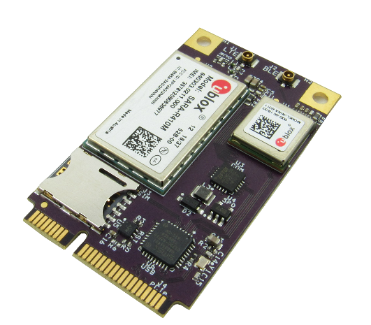
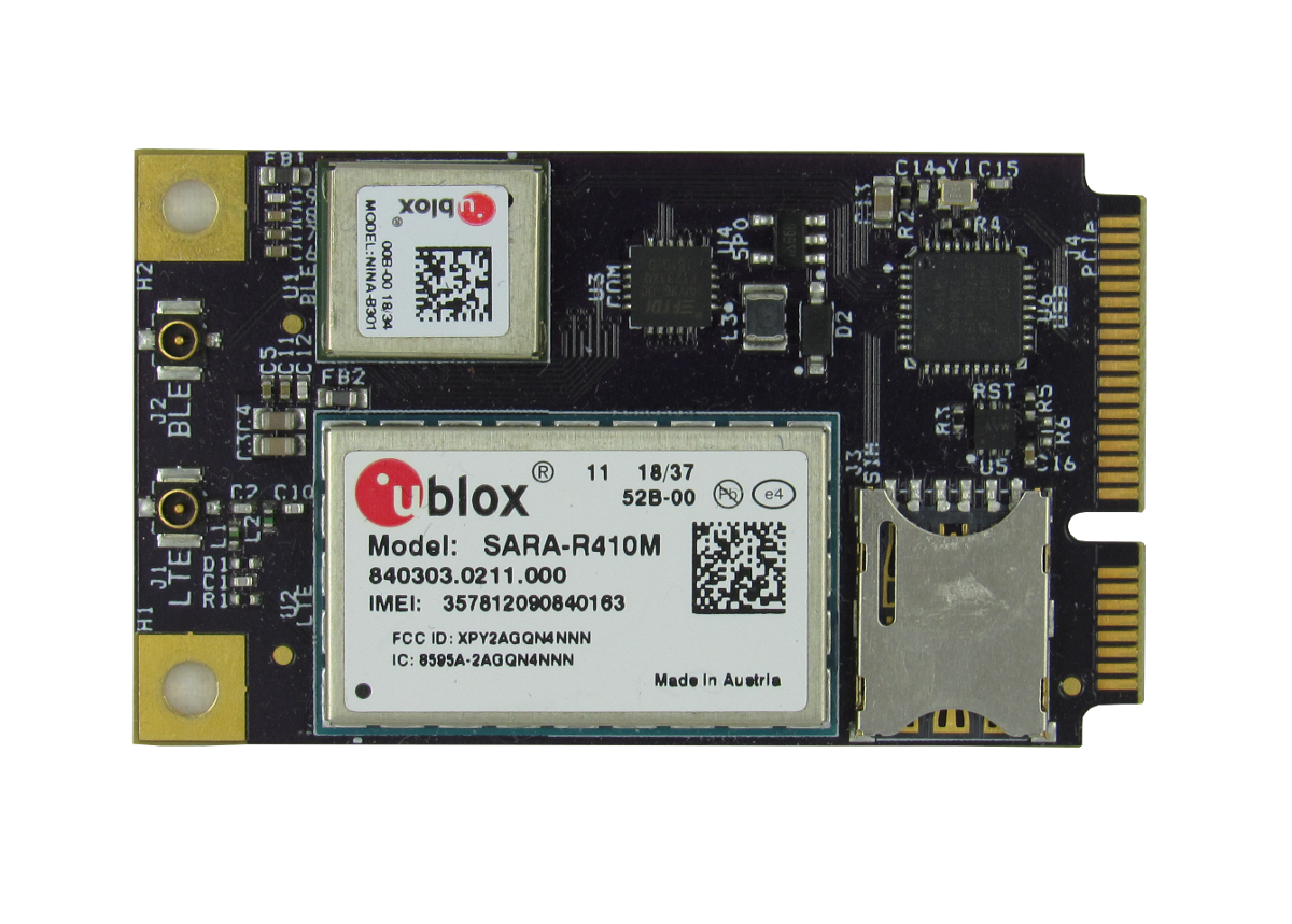
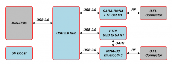
The GW16126is a Mini-PCIe Radio card that provides cost-effective, low power cellular connectivity and Bluetooth Low Energy (BLE) for Internet of Things (IoT) networks. The GW16126 features a u- blox SARA-R410M LTE Cat M1 modem for low bandwidth cellular connectivity to the cloud. A nano- SIM socket is included with a Hologram IoT starter SIM. The GW16126 also features u-blox NINA- B301 Bluetooth 5 Low Energy radio used for communicating with and reading BLE sensors. Both the cellular modem and BLE radio have dedciated separate u.Fl antenna connectors for connection to an external antenna. This radio card operates in any standard Mini-PCIe socket that includes a USB 2.0 interface. This radio card enables a Gateworks SBC as a remote IoT Cellular Gateway with the ability to communicate with BLE sensors.
This is the 2018, February submitted for the nanotechnology image of the month.
A long time ago in a galaxy far, far away…. *star wars theme* …. WAIT! In fact, the story unfolds right here and right now in the CMi with R2D2 battling armies of stormtroopers inside the SEM Merlin chamber. This 3D replica was printed with the Nanoscribe professional photonic GT using two-photon absorption mechanism, in galvoscanning mode. The model is 250 micrometers tall and was written in about 3 hours. Next scientific project: Millenium Falcon J !
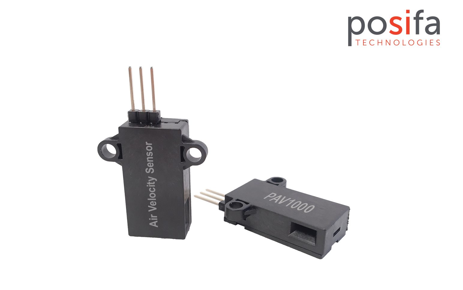
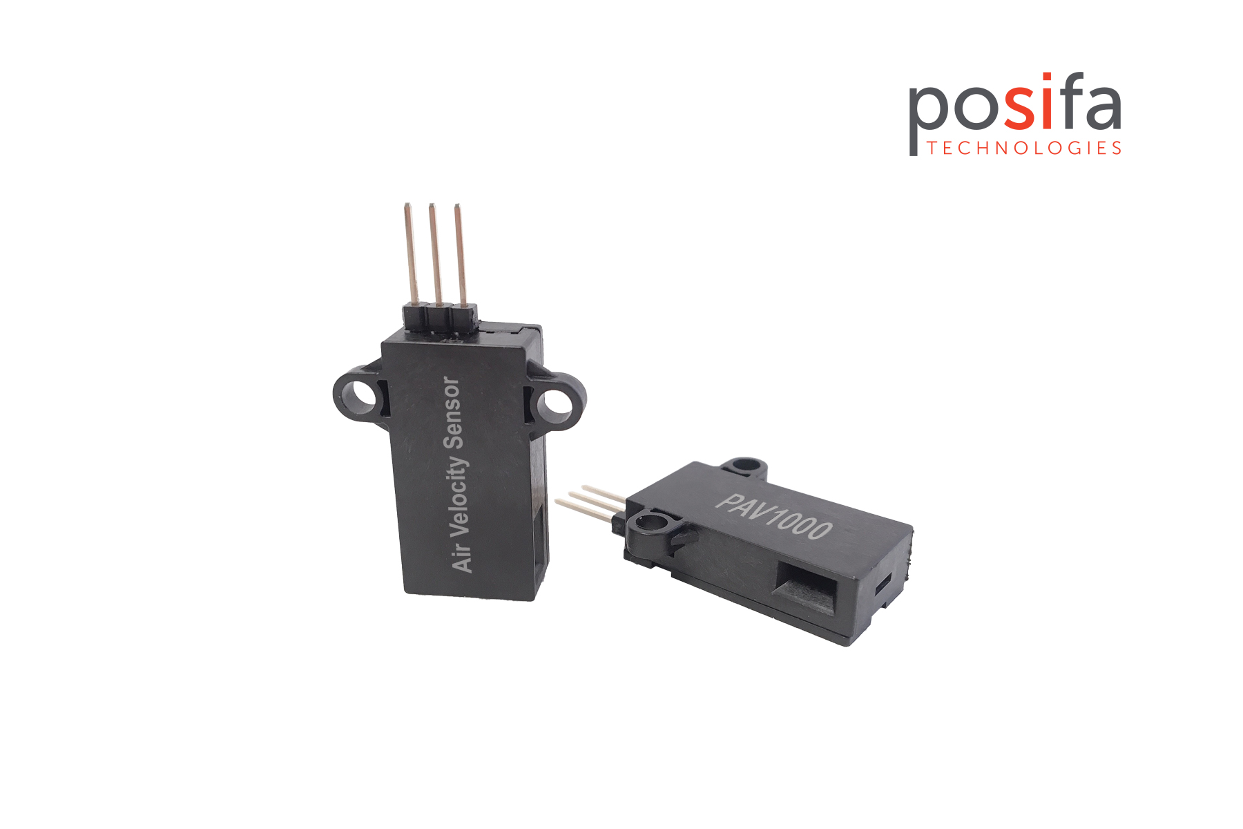
Posifa Technologies today announced its new PAV1000 series of air velocity sensors for data center thermal management and HVAC applications such as filter monitoring . Measuring air velocity at 7 m/s (PAV1005V) and 15 m/s (PAV1015V), the devices offer extremely fast response times of 125 ms typical in a compact, robust package.
The PAV1000 series was designed as an economical, high-performance air velocity sensor for thermal management and filter monitoring in even the most space-constrained locations, such as rack enclosures with air cooling in data centers . Unlike thermistor-based solutions, the Posifa MEMS sensor core is minimally affected by ambient temperature changes and provides instant real-time feedback on proper air flow at critical locations .
Air velocity data perfect ly complement s temperature information to provide the best insight into thermal efficiency. By i dentifying areas that require unusually high air flow to maintain stable temperatures , layouts can be modified to reduce cooling demands f or increased energy savings. In HVAC applications , air velocity measurements can be used to determine when filter s need to be replace d. This ensures hardware is adequately protected during heavy use , while allowing customers with light usage requirements to benefit from extended change intervals.
The devices feature Posifa’s third-generation thermal flow die, which uses a pair of thermopiles to detect changes in temperature gradient caused by mass flow. The result is excellent repeatability of 1 % FS and accuracy of 5 % FS. The solid-state thermal isolation structure on the sensor die eliminates the need for a surface cavity or fragile membrane used in competing technologies, making the sensor resistant to clogging and pressure shock.
The PAV1000 series offers an output voltage range from 0 VDC to 4.5 VDC, supply voltage from 5 VDC to 5.5 VDC, and supply current of 20 mA. The devices operate over a -25 ° C to +85 ° C temperature range.
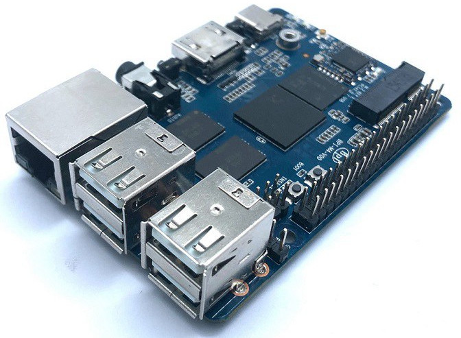
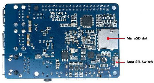
This year SinoVoip revealed Banana Pi BPI-M4 – a mid-range SBC that runs Android 8.1 or Linux on a quad -A53 Realtek RTD1395 SoC featuring HDMI, M.2, WiFi/BT, 40-pin GPIO, PoE support, and 5x USB ports. SinoVoip is well-known for its Allwinner SoC based single board computers and the Banana Pi line of product. But this BPI-M4 SBC sports a quad-core, Cortex-A53 based Realtek RTD1395. Their earlier BPI-W2 router board was also powered by a Realtek quadcore SoC.
Banana Pi BPI-M4 SBC
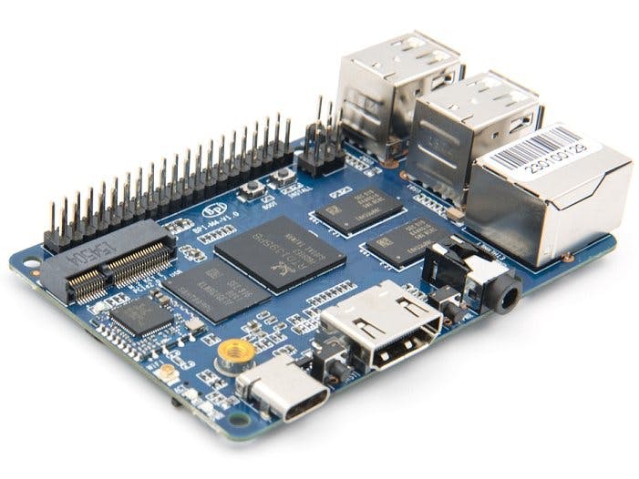
The Banana Pi BPI-M4 is said to have a Raspberry Pi layout, despite being a bit larger in both dimensions with a footprint of 92 x 60mm. Unlike the RPi SBCs, there’s an option for 2GB in addition to 1GB RAM, and it’s DDR4. You also get 8GB to 64GB eMMC and a microSD slot. The clock rate of RTD1395 SoC is not listed but the Cortex-A53 foundation and Mali 470 MP4 GPU would make it more powerful than the BPI-M2 series of boards like BPI-M2 Berry, BPI-M2 Magic, and BPI-M2 Zero. The 1.8GHz octa-core BPI-M3, with PowerVR SGX544MP1 GPU, might outperform it though this is not confirmed yet.
Banana Pi BPI-M4, front view
Banana Pi BPI-M4, back view
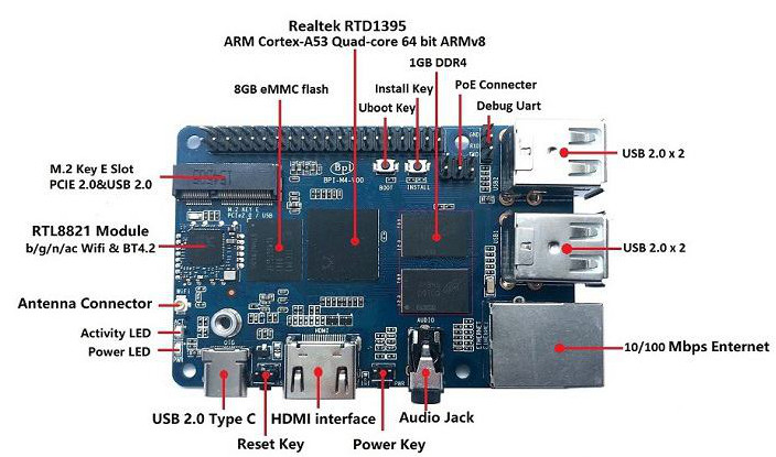
The Ethernet speed of BPI-M4 is 10/100Mbps, and there’s a Power-over-Ethernet (PoE) connector that supports the official Raspberry Pi PoE HAT. The YouTube video below shows the SBC booting Android 8.1.1 via PoE power. SinoVoip also states it will run full Linux with a new Realtek SoC, which may take a while. The Banana Pi BPI-M4’s HDMI port is limited to 1080p. This SBC also lacks the support for H.265. There are 4x USB host ports on BPI-M4. You also get a USB Type-C port that offers another power alternative. The board ships with WiFi-ac and BT 4.2. A cellular modem can also be attached using the M.2 E-Key slot. This 5V board has power and boot buttons.
The key specifications are:
Processor:
Realtek RTD1395 (4x Cortex-A53)
ARM Mali-470 MP4 GPU
Memory/Storage:
RAM — 1GB or 2GB DDR4 RAM
8GB eMMC expandable to up to 64GB
MicroSD slot for up to 256GB
Wireless:
802.11b/g/n/ac WiFi with Bluetooth 4.2 (RTL8821 module)
antenna connector
M.2 (see farther below)
Networking:
10/100 Ethernet port
PoE connector for RPi PoE HAT
Media I/O:
HDMI port with support for 1080p and multi-channel audio
3.5mm audio jack
Other I/O:
4x USB 2.0 host ports
USB 2.0 Type-C port
Debug UART
Expansion:
40-pin, RPi 3-compatible expansion header with 28x GPIO, UART, I2C, power, SPI (or PWM), etc.
The Banana Pi BPI-M4 is available on AliExpress for $38 (plus $5.26 to the U.S.) with 1GB RAM and 8GB eMMC. More information may be found on the BPI-M4 AliExpress page and the wiki.
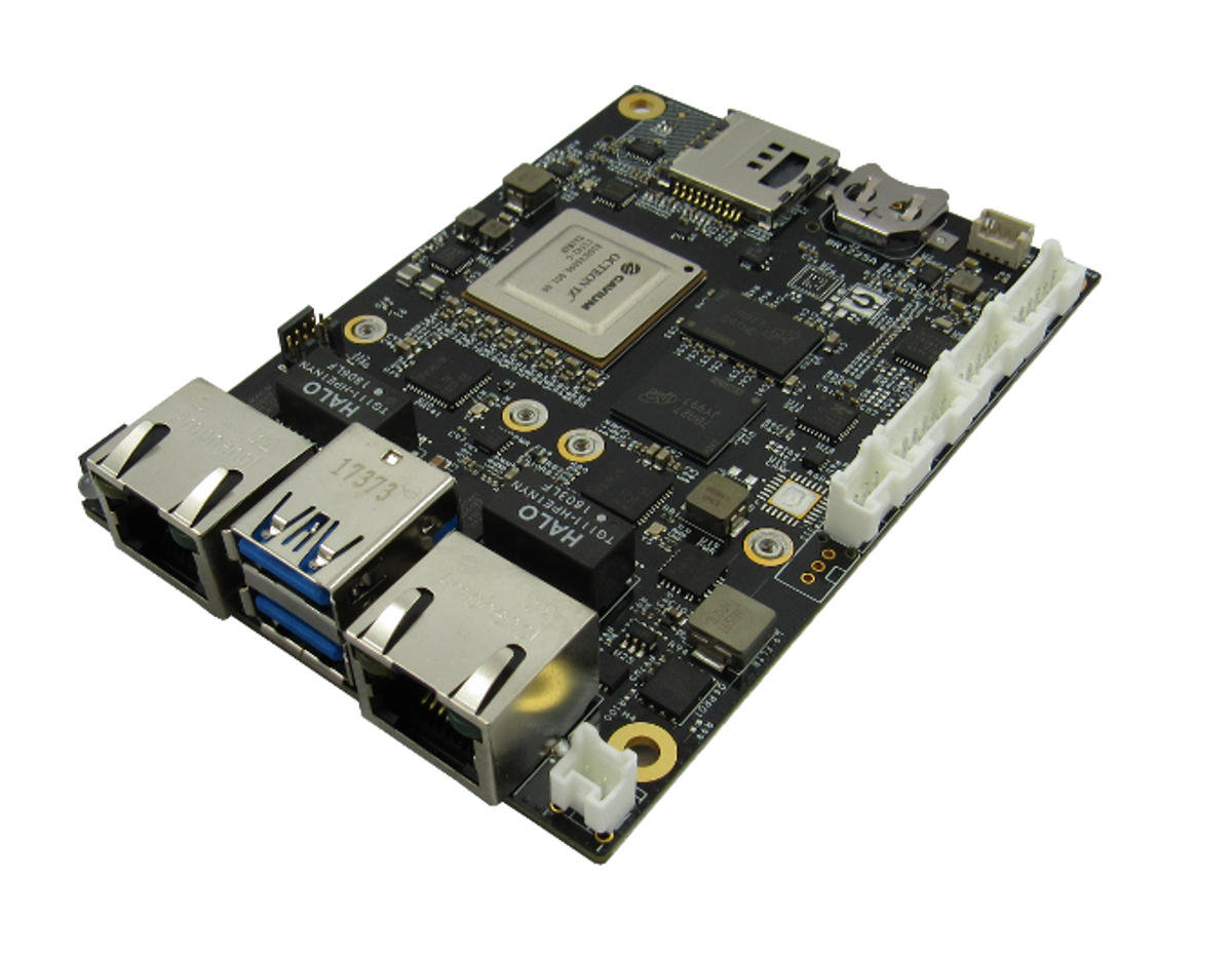
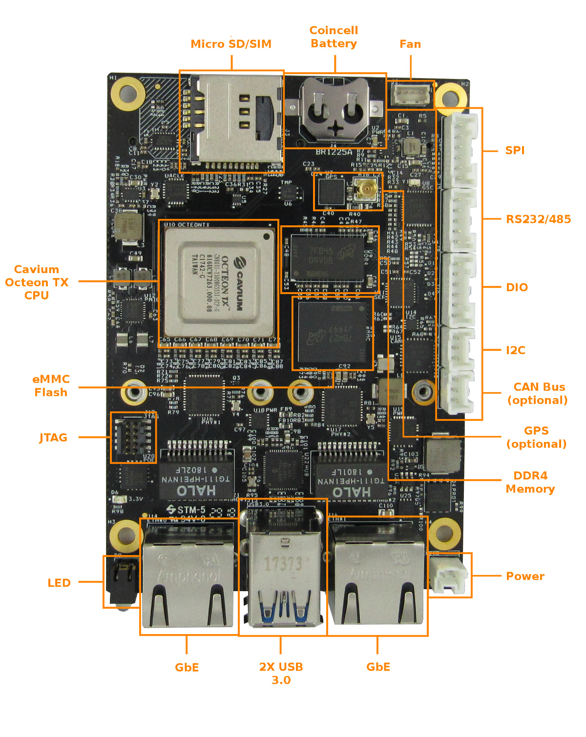
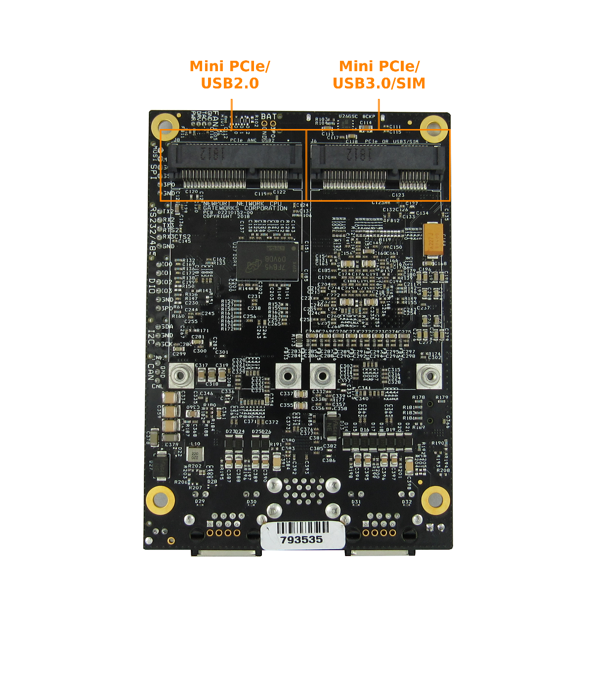
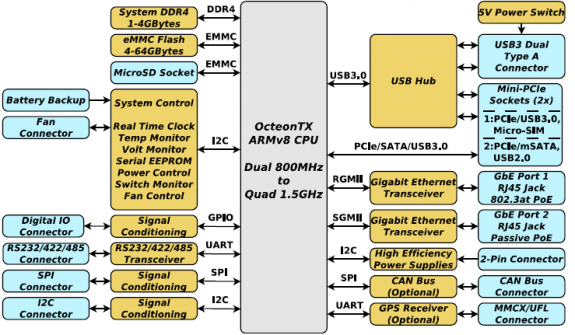
High Performance Single Board Computer for Networking with 2x Mini-PCIe Sockets, 2x Gigabit Ethernet Ports, and USB 2.0/3.0
The GW6200 is a member of Gateworks 6th generation Newport family of single board computers targeted for a wide range of indoor and outdoor networking applications. The single board computer features the Cavium OcteonTX™ Dual Core ARMv8 SoC processor operating at 800MHz, 1GByte of DDR4 DRAM, and 8GBytes of eMMC System Flash. Two Mini-PCIe expansion sockets support a combination of 802.11abgn/ac wireless radios, LTE/4G/3G CDMA/GSM cellular modems, mSATA drives and other PCI Express peripherals. Additional peripherals include two Gigabit Ethernet ports and two USB 2.0/3.0 ports. The Gateworks System Controller provides embedded features such as real time clock, voltage and temperature monitor, fan control and monitor, serial EEPROM, and advanced power management with programmable board shut-down and wake-up for remote sensor applications. A wide-range DC input power supply provides up to 10W to the Mini-PCIe sockets for supporting the latest high-power radios and up to 10W to the USB 2.0/3.0 jacks for powering external devices. Power is applied through 2-pin connector or an Ethernet jack with either 802.3at or Passive Power over Ethernet. Both OpenWrt and Ubuntu Linux Board Support Packages are supported.