SolidRun has launched a new single board computer named as HummingBoardCBi. HummingBoard CBi merges the powerful HummingBoard platform with the CAN bus and RS-485 connectors – tailor-made for industrial and production floor applications. They actually swapped the HDMI of theirHummingboardEdge SBC with CAN and serial port to design this new industrial variation. This board runs Linux on an i.MX6 MicroSOM just like the Hummingboard Edge.
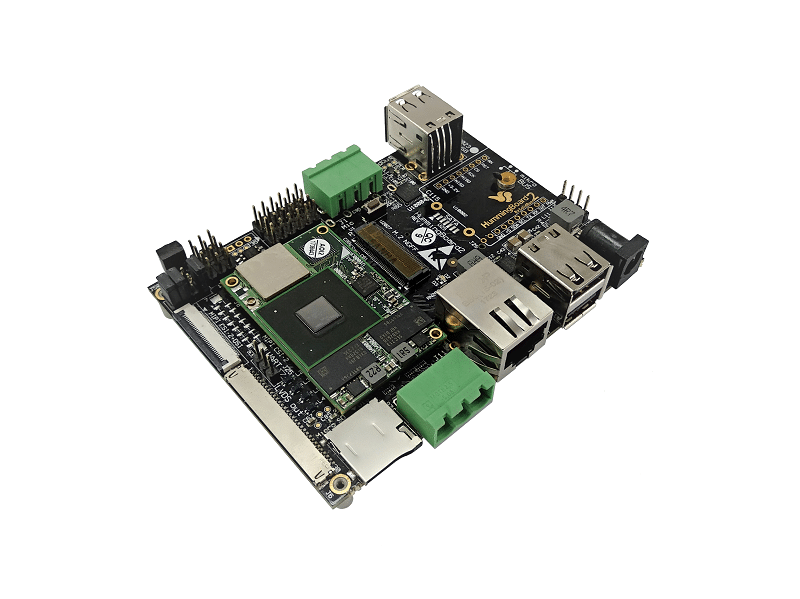
HummingBoard CBi by SolidRun
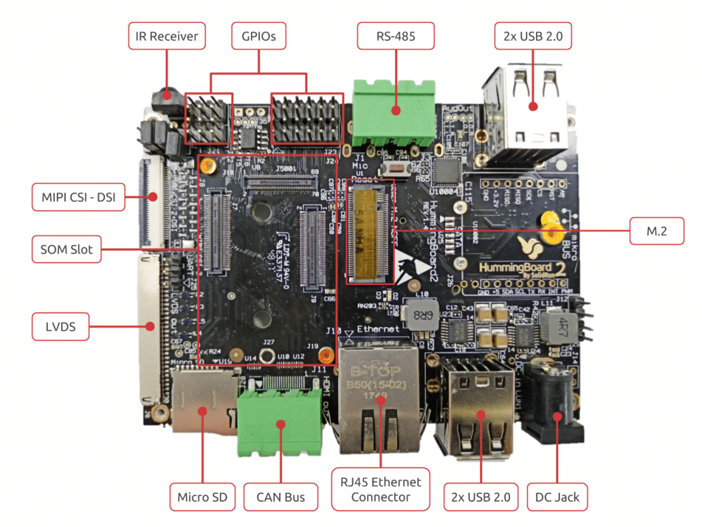
The sandwich-style board, which ships with a regular enclosure, has the same 102 x 69mm footprint of the Edge and the HummingBoard-Gate and ships with open schematics. In their website, they represented this industrial SBC as a powerful carrier board for a range of interchangeable i.MX6 based SOMs, developed for the demanding industrial automation market to offer robust features for the smart production floor of tomorrow. CANbus (Controller Area Network) is a standard connector originally developed for the automotive industry. It offers a rugged connectivity option for designing a physical network in a harsh environment and has been used in a variety of sectors for a range of applications from vehicle engines to aviation, medical, smart building, or even robotics.
The HummingBoard CBi SBC/mini-PC runs Linux on the same NXP i.MX6 equipped MicroSOM modules with dual-or quad-core 1.2GHz Cortex-A9 cores. (A single-core Solo model is listed in the specs, but not yet available.) Debian, Yocto Project, BuildRoot, and OpenWrt stacks are available with a Linux 4.4x kernel, and Android support is in the works. It offers up to 2GB memory, USB 2.0 ports, Mini PCIe, M.2 and even a SIM card slot, all on a compact (102mm X 69mm) ARM-based and energy efficient industrial single board computer. Other features include the usual bandwidth-limited GbE port, 4x USB 2.0 ports, 8GB eMMC, and a microSD slot. Although it’s not listed on the product page, the shopping page says the board provides a WiFi/Bluetooth module.
The key specifications are:
Processor (via MicroSOM i.MX6): NXP i.MX6 (2x or 4x Cortex-A9 cores @ up to 1.2GHz)
Memory/Storage:
1GB (Dual) or 2GB (Quad) DDR3 RAM (via MicroSOM i.MX6)
8GB eMMC (via MicroSOM i.MX6)
MicroSD slot
M.2 2242 slot with storage support
Wireless: WiFi/Bluetooth module
Networking: Gigabit Ethernet port (limited to 470Mbps bandwidth)
The HummingBoard CBi is available with 8-week shipping time for $189 (dual-core with 1GB RAM) or $255 (quad-core with 2GB). More information may be found on the HummingBoard CBiproduct, developer, and shopping pages.
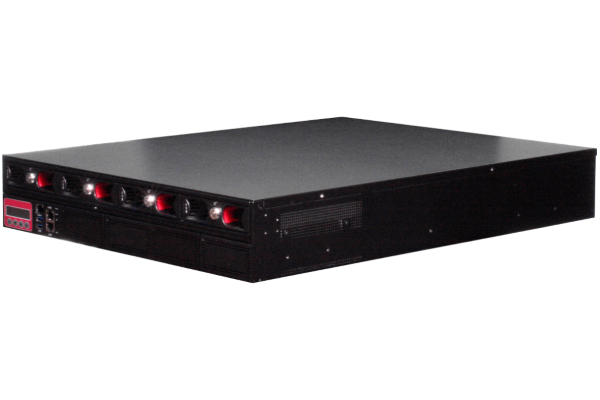
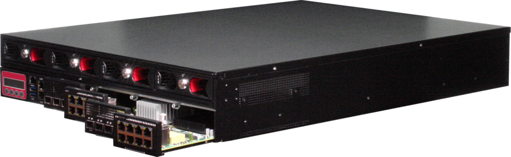
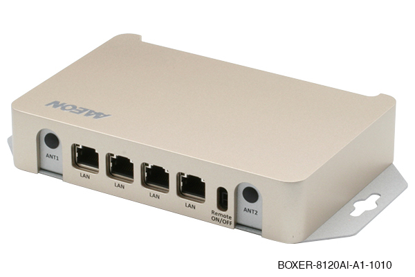
AAEON, an industry leader in network security solutions, has collaborated with Intel to deliver a powerful network platform utilizing the latest 2nd Generation Intel® Xeon® Scalable processors. The result of this effort is the FWS-8600 2U rackmount network appliance, the most powerful network appliance from AAEON yet.
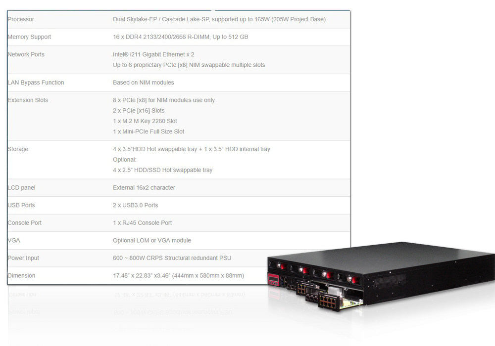
The FWS-8600 network appliance is built to handle powerful network applications, from Unified Threat Management (UTM) to Software Defined Networks (SDN) and Network Function Virtualization (NFV). These features come from the appliance’s 2nd Generation Intel Xeon Scalable processors, offered with up to 20 cores per processor. The FWS-8600 uses a dual processor configuration, meaning users can have up to 40 processor cores powering their networks. The FWS-8600 also features four lockable hard drive bays, and 16 DDR4 memory slots, with support for up to 512GB of RDIMM ECC RAM.
Thanks to the speed and power of 2nd Generation Intel Xeon Scalable processors, the FWS-8600 can support LAN throughput up to 300~400 Gbs, ten times more than typical machines currently available, according to AAEON testing. This means the FWS-8600 can take the place of multiple network devices, simplifying network infrastructure. With support for network virtualization and software defined networking, the FWS-8600 can ensure high bandwidth and high data flow for your networks.
“With the power of 2nd Generation Intel Xeon Scalable processors, we can offer our customers a powerful, robust network platform that’s ready to handle the needs of the high data, high speed environment of IoT networks,” said Ulysses Yu, Product Manager of AAEON Network Security Division. “From a dedicated SDN controller, to a hybrid switch system, the FWS-8600 with the 2nd Generation Intel Xeon Scalable processor can power industrial network and IoT solutions,” added Ulysses.
The 2nd Generation Intel Xeon Scalable processor is the latest line of processors built for industrial and enterprise applications. AAEON looks forward to expanding our offerings of products featuring the 2nd Generation Intel Xeon Scalable processors.
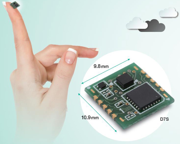
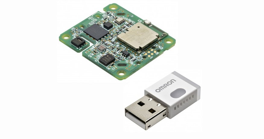
Fishmograph allows to precisely monitor earthquakes involving our house using the D7S sensor, sending us an email notification for every event detected, allowing us to take people and things to safety. Fishmograph is based on Fishino 32 and the excellent low-cost D7S sensor developed by Omron.
Italy is one of the Mediterranean countries with the highest seismic risk and this very unfavourable record is due to its geographic location, riding across the African plaque and the Euroasian plaque (we are talking about tectonic plaques); this “unfavourable” position causes the very high number of earthquakes taking place every day in our country, which, however, fortunately, are so weak that can be detected only by instruments, whilst a very small percentage has enough intensity to cause damages to people or things.
This sensor, which we have previously introduced and analyzed in this magazine in issue 222, guarantees a high degree of precision when detecting earthquakes and has the very useful automatic danger level evaluation feature for electronic devices, emitting a shutoff signal when intensity is 5 or higher on the JMA (Japan Meteorological Agency) intensity scale, or it can emit a collapse signal when a variation in its physical position is detected (possibly due to the floor collapsing).
Fishmograph – Omron’s D7S sensor based seismograph – [Link]
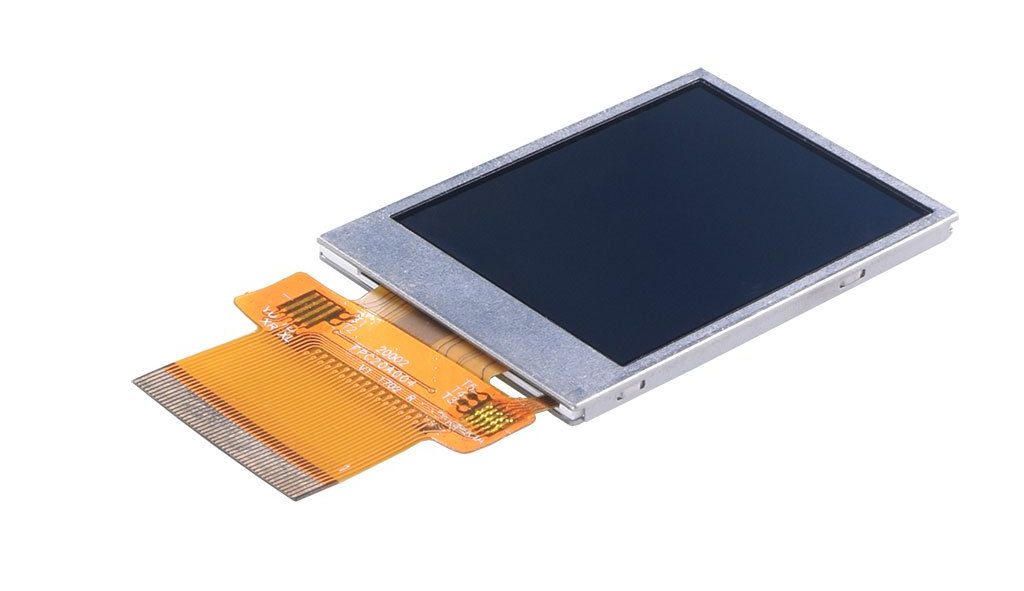
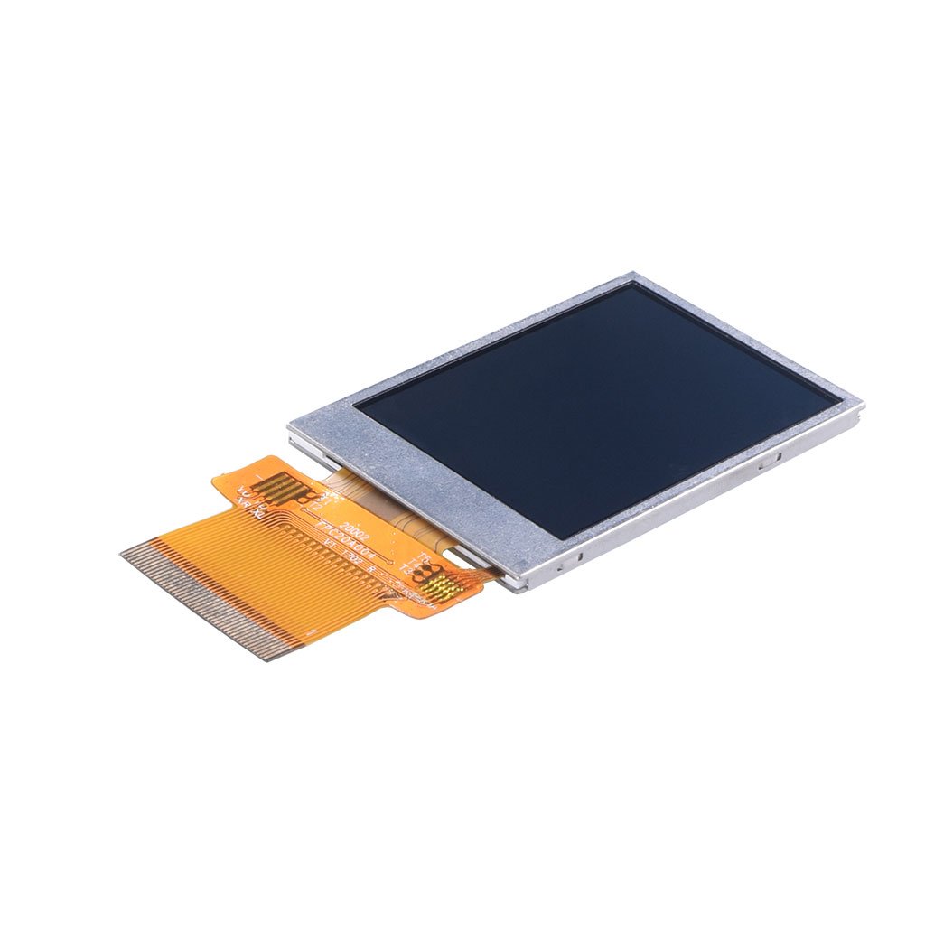
This is a new 2″ Transflective Display Panel with part number DM-TFT20-386 available from www.displaymodule.com for $15.99 . It can be interfaced to any microcontroller through SPI.
We can say that an Interrupt is an automatic transfer of software execution in response to a hardware event that is asynchronous with the current software execution. As it’s name says, interrupts, “interrupt” the normal program flow to perform an action (run another code block, function, etc.) and return back to the normal program flow when the action is completed. Interrupts can be established for events such as a counter’s number change, a pin changing state (from low to high or high to low), serial communication receiving information, or the Analog to Digital having established a conversion, etc., depending on what is supported by the microcontroller you are working with. For today’s tutorial, we will focus on interrupts as a result of pins changing state and how these can be used on the Arduino.
To monitor their digital pins for changes, microcontrollers by default use a technique generally referred to as “polling“, which means they constantly check the digital pins to know if any change has occurred. This usually takes a lot of the microcontroller’s resources and reduces its response time which may not be a problem in most applications but could be important in time-critical ones. One of the solutions usually adopted in scenarios where all the negatives of polling need to be eradicated is the use of external Interrupts. Interrupts provide the microcontrollers with a way of multitasking such that a particular digital pin does not need to be continually polled, as the pin would by itself signal the microcontroller and immediately pause the operations when a change occurs. Asides in time-critical applications, where the microcontroller needs increased response rate, Interrupts are widely used in power saving applications for all kind of device, from smartphones and their power button to your PC and the spacebar and the application goes on.
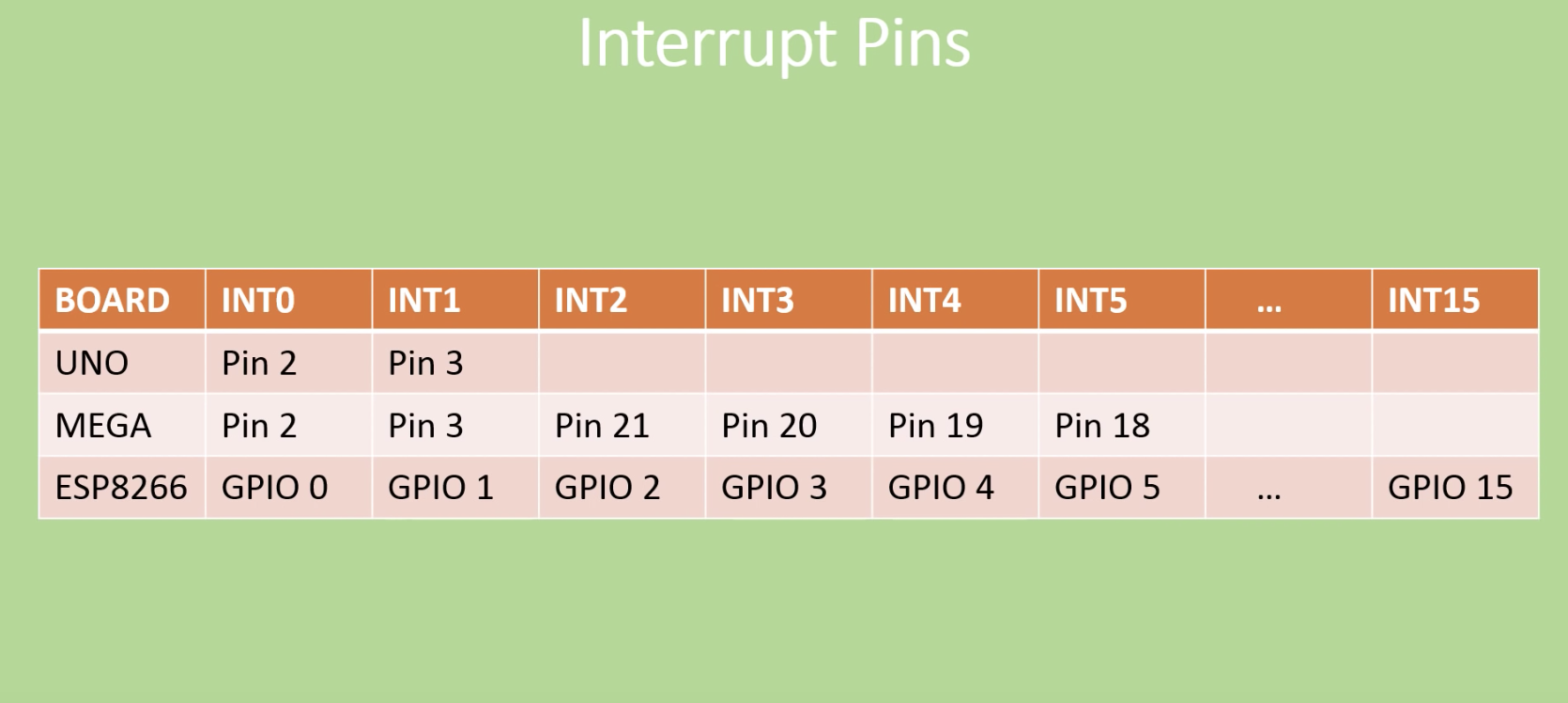
Interrupt Pins of different Arduino Boards
The number of external interrupts possessed by microcontrollers differs from one microcontroller to the other. For example, the Arduino boards, from UNO to Duemilanove, have only two interrupts which are located on digital pins 2 and 3. Other boards like the Arduino Mega has 6 while the esp8266 (ESP 12e) has about 16 interrupt pins.
For today’s tutorial, We will look at how the interrupt can be used in an Arduino project and as an example, we will connect a switch to one of the interrupt pins on the Arduino and use it to control a LED which is turned on/off when the interrupt is triggered.
Required Components
The following components are required to build today’s tutorial;
As usual, the exact components used for this tutorial can be bought via the link attached to them.
Schematics
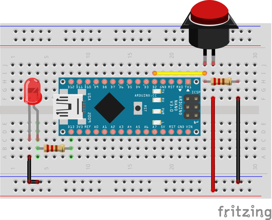
The schematics for this project is quite simple. We need to connect an LED and a pushbutton to the Arduino, in that way than when the pushButton is pressed, an interrupt is triggered on the Arduino to control the on/off state of the LED.
Connect the components as shown in the schematics below.
Schematics
As mentioned initially, either of the Arduino Uno and the Nano can be used for this project as they all have the same pin configuration, the same number of interrupt pins and the interrupt is located on the same pin across the two boards.
Asides using the switch as the trigger, a PIR Motion sensor can also be used to trigger the interrupt when motion is detected. To use the PIR sensor, connect it to the Arduino as shown in the schematics below.
Motion Interrupt Schematics
Since motion sensors behave like a switch, the same code can be used with the same schematics.
Code
The code for this project is quite easy. As mentioned at the beginning, our goal for today’s project is to learn how to perform an action (turn on/off and LED in this case) when an interrupt is triggered. Thus we will program the Arduino to watch out for a “rising edge” interrupt on the pin to which the button is connected and respond by turning the LED on.
To do a quick explanation of the code; We start by creating a boolean variable “ledon” to store the state of the LED. This helps the sketch remember the last state of the LED.
//Written by Nick Koumaris
//info@educ8s.tv

volatile boolean ledOn = false;
Next, we write the void setup() function. We start by declaring the pinMode of the pins to which the LED and the PushButtons are connected. With that done, we then call the attachinterrupt() function to provide the microcontroller with details of the interrupt operation. The attachinterrupt() function takes 3 arguments; The interrupt pin, the function to run when triggered, the type of trigger to look out for. The trigger could be either of “rising” (pin goes from low to high), “falling” (pin goes from high to low) or “either” (either of the two).
Since we won’t be repeating any action, we will leave the void loop() section blank. Thus, up next is the buttonpressed() function. This function is called when a rising edge signal triggers the interrupt. The function simply changes the state of the LED, turning it OFF if it was ON and turning it ON if it was OFF.
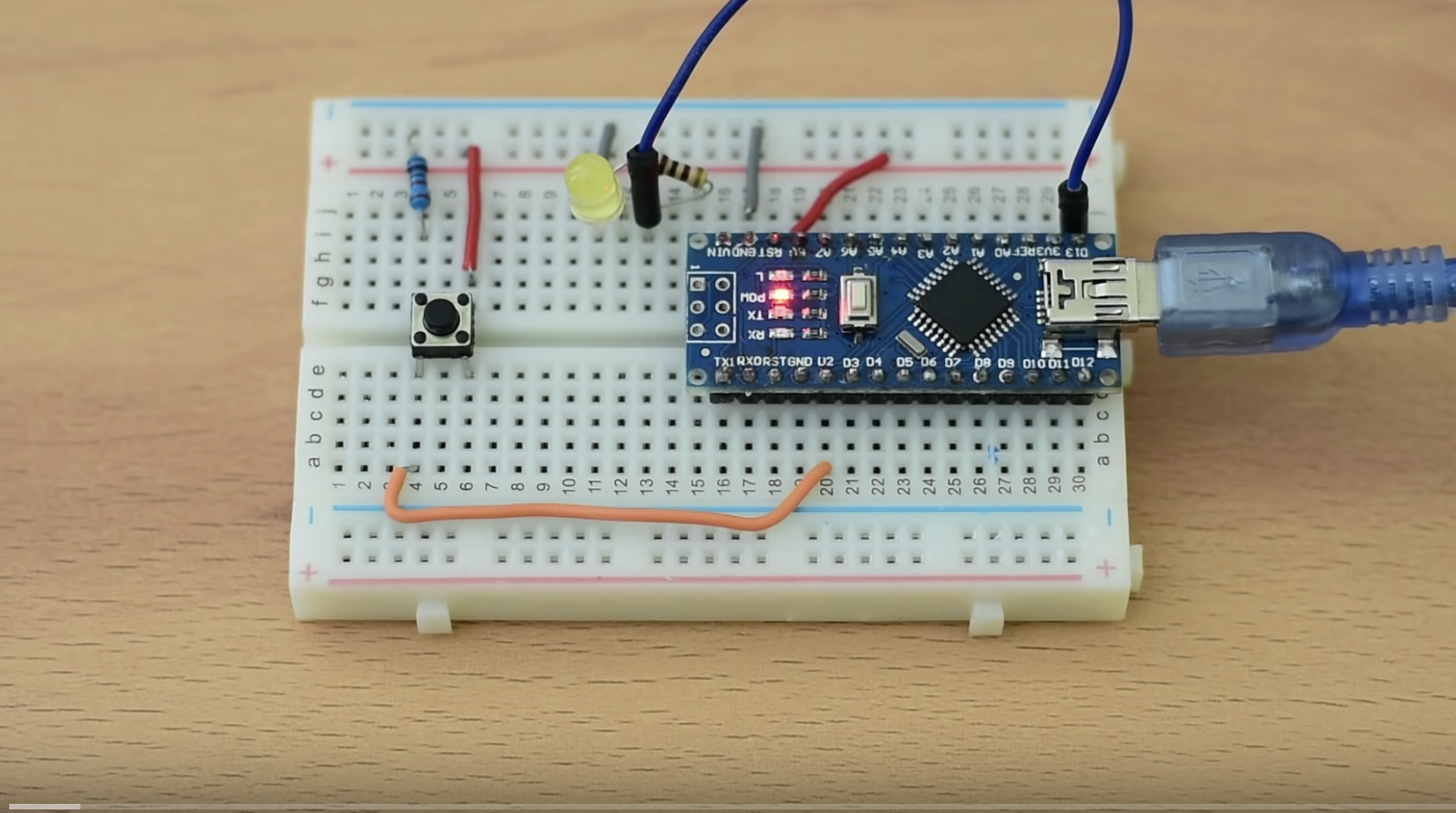
Go over the schematics once again to ensure everything is connected as it should then connect your Arduino to the computer and upload the code to it. You can now press the push button to see the LED respond.
Final thoughts
Interrupts are used for a plethora of applications including; implementing low power algorithms, eradicating polling to preserve system resources, and to ensure quick response in time-critical applications like alarm systems.
That’s it for today’s project. Thank you for reading. Do reach out via the comment section if you have any question or comments.
The video version of this tutorial is available on Youtube.
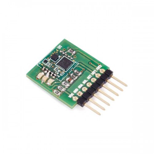
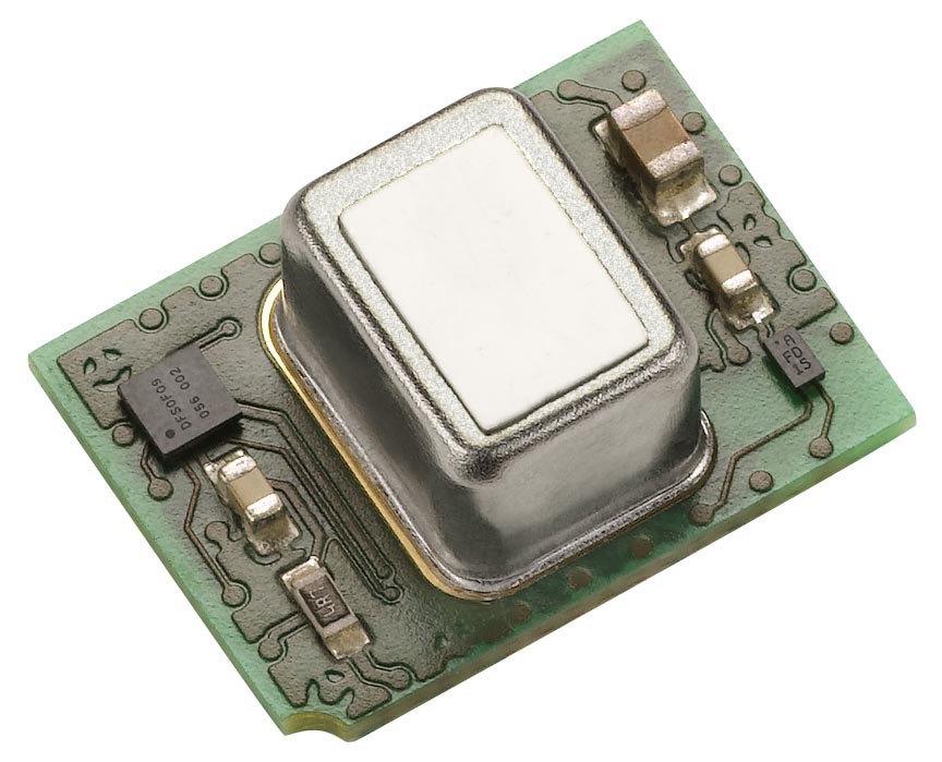
Omron’s 2JCIE environmental sensors are IoT sensors integrated with Bluetooth. These sensors are capable of tracking eight different environmental factors which include: temperature, humidity, light, UV index, barometric pressure, noise, acceleration and VOC (Volatile Organic Compounds) with wireless communication functionality in an ultra-small footprint.
The sensors can be used in the home to monitor room environments, sleeping conditions, infants, and the elderly. They can also be used in offices or factories to monitor conditions of work environments. Or, they can be used outdoors to alert users to weather changes and monitor UV exposure.
Features & Benefits
Multiple sensors (such as temperature, humidity, light, barometric pressure, sound noise), in one package, provide various information at same time
Information loss is prevented by saving date inside of built-in memory even if communication is not established
Small dimension packaging, allowing use anywhere
Industries
Appliance & Climate Control
Other
Applications
Smart home (example- room monitor for comfortable sleep conditions), building (example- office environment monitor), weather conditions, real estate, vacation rental
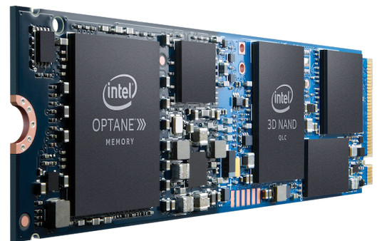
A leaked Intel roadmap reveals launch plans for Intel Core and Atom processors through the end of 2021. Of interest is a hybrid Lakefield processor design that combines a 10nm Ice Lake core and 4x Atom Tremont cores. The roadmap contains several surprises, like Intel’s plans for a market launch of its 10nm U- and Y-series Ice Lake chips, and also its partially Ice Lake-based Lakefield processors by the end of June, instead of the expected end-of-year launch.
Another info is that Lakefield will have a 3-5W TDP, which is lower than any Atom-level CPU to present. Intel is exploiting a chiplets design approach for the Lakefield, that incorporates two different product lines with cores fabricated with different processes on a single processor. For example, a 10nm Ice Lake “Sunny Cove” core will be incorporated with 4x 10nm Tremont architecture cores. The 12mm SoC will offer longer battery life than previous Atom SoCs, alongside featuring Intel Gen11 graphics. Lakefield’s high-powered Ice Lake core utilizes Sunny Cove, a new CPU microarchitecture with power/performance improvements and acceleration of tasks like AI and cryptography. According to Intel, Sunny Cove “enables reduced latency and high throughput, as well as offers much greater parallelism.
The Lakefield Atom chips will also utilize Intel’s first 10nm Atom architecture, known as Tremont, which in 2021 will be followed by a Gracemont architecture. The roadmap hints that the initial Ice Lake release will be limited, hopefully, there will be a larger quantity next year. There will also be another 10nm Intel Core called Tiger Lake. The Tiger Lake will also be initially limited to up to quad-core U-series and even lower-powered Y-series designs.
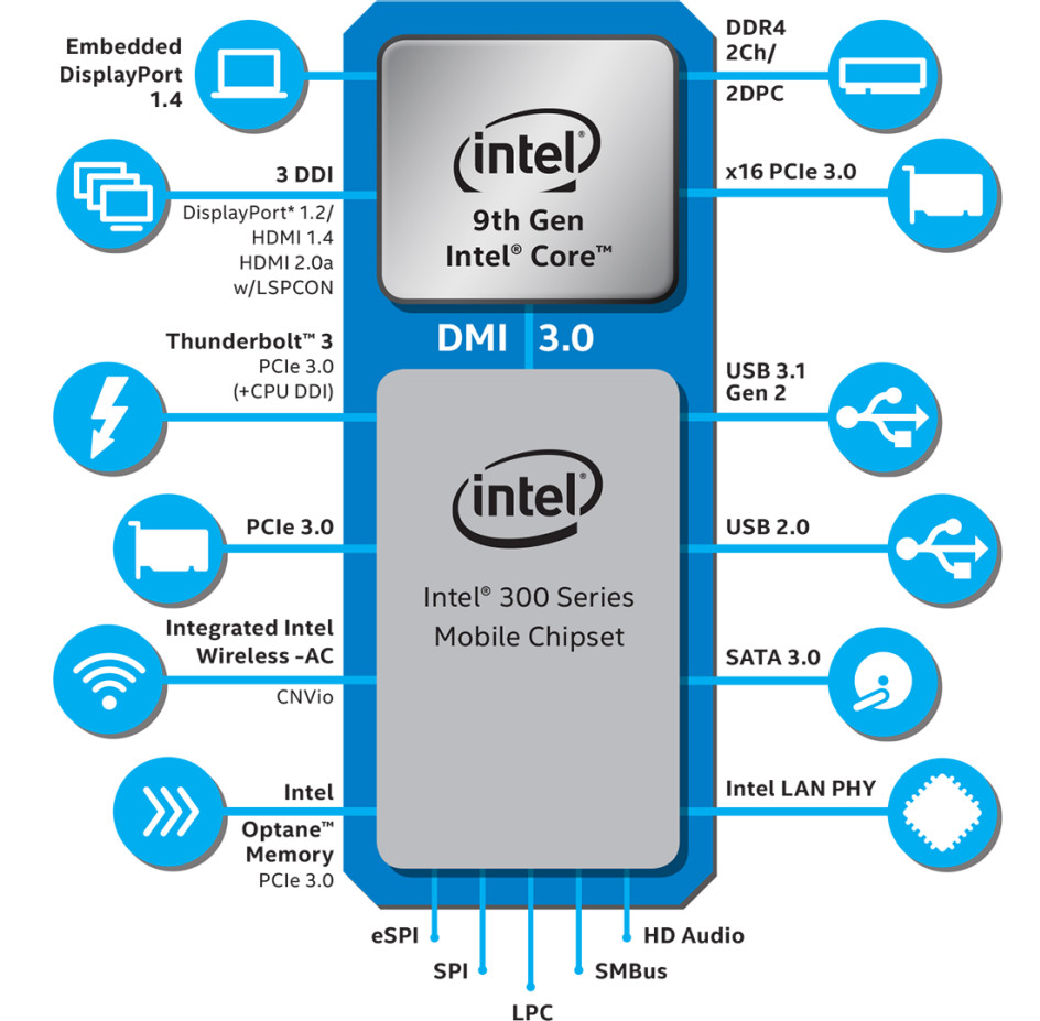
Intel 9th Gen feature diagram 9th Gen Mobile H-series processors
The roadmap also hints that Intel is planning at least two more 14nm Core generations. One of them is the Comet Lake, which is due in the second half of this year, beginning with U-series models. A higher powered H-series model will follow later, and a super low—power Y-series will follow in 2020. The Comet Lake will feature 6-core U-series chips for the first time, and also the first 10-core H-series models. A Rocket Lake design will be due in Q3 2020. It combines a 14nm CPU with 10nm graphics. This is another example of chiplets. Other Rocket Lake models will utilize 14nm for both CPU and GPU.
Visit Intel’s Newsroom for more information on Intel’s April announcements
AAEON is leading the industry with embedded solutions for AI and edge computing applications. Whether your project involves drones, robots, smart security systems, or intelligent street lights, AAEON has the hardware solutions to meet any need. With experience and expertise in creating rugged industrial platforms, these AI platforms will work anywhere you need.
AAEON meets the needs of developers for AI platforms by offering a mix of purpose-built compact and rugged systems, low-power high-performance maker boards configurable for any application, and AI modules which can install quickly and easily, expanding the capabilities of almost any system across AAEON’s entire range of embedded solutions.
Purpose built systems include the BOXER-8100AI family, powered by NVIDIA® Jetson® TX2. This powerful module pairs the Dual-Core NVIDIA Denver 2 64-Bit CPU with the Quad-Core ARM® Cortex®-A57 MPCore, offering up to 256 CUDA cores for embedded AI applications. The BOXER-8100AI family offers various I/O configurations, making each model suitable for a variety of AI tasks and connecting to different hardware, such as PoE or MIPI cameras. The BOXER-8100AI family feature compact sizes and fanless design, allowing these systems to fit anywhere and work anywhere.
AAEON’s range of UP maker boards offer developers ultimate flexibility and configurability to tailor our systems to their needs. Whether it’s the speed of the UP Squared or expandability of the UP Core Plus, our UP products can be built and configured to meet your needs. With low-power high-performance components, they are excellent for mobile applications such as inspection drones and service robots.
AAEON’s innovative embedded boards and systems have always been designed with expandability as a feature. Utilizing our innovative AI Core X and AI Core XM family of Intel® Myriad™ X modules, virtually all of our embedded systems can be deployed in AI and edge computing applications. This provides even greater flexibility for developers and clients looking for an AI solution tailored to their needs. Whether it’s our VPC-5600S deployed for intelligent security and virtual fence applications, or our din-rail mounted BOXER-6750 powering facial recognition and machine vision applications in a compact, easy to install form factor, there’s no end to the possibilities with AI Core X from AAEON.
AAEON also provides end-to-end support to deploy AI edge computing and AIOT networks. With our range of AIOT gateways and our very own LoRa Node, AAEON makes configuring and deploying AI Edge networks easier than ever. For more traditional networks, our network appliances are designed to handle the high-data flow requirements of AI edge computing while still providing vital services such as network function virtualization and unified threat management.
AAEON has proven itself a leader in industrial embedded design through constant innovation and developing for the future. In the near future we will be expanding our embedded AI systems even more, to power demanding tasks such as Automated Optical Inspection, and incorporating advanced AI optimized technologies such as the 2nd Generation Intel® Xeon® Processors (formerly Cascade Lake). AAEON also continues to offer our manufacturer services and OEM/ODM support, empowering developers and partners with the ability to configure and design systems to fit their exact and unique needs, speeding up development and reducing deployment times.
With AAEON’s range of compact embedded AI Edge computing systems and the innovative AI Core X, our clients will have no trouble finding the right solution for their application.
Once again, Sensirion trailblazes innovation in environmental sensing to create healthier and more productive environments for people. At this year’s Sensor+Test 2019 in Nuremberg and SensorsExpo 2019 in San José, the expert in environmental sensing, Sensirion, is announcing the SCD40 – the first miniaturized CO2 and RH/T sensor that fits in a space of just one cubic centimeter. This disruptive innovation is based on the photoacoustic sensing principle and combines minimal size with maximum performance to open up numerous new integration and application possibilities. Due to its unprecedented price-performance ratio, the SCD40 is especially well suited for high-volume and cost-sensitive applications.
Sensirion’s profound expertise in miniaturizing sensors has enabled a breakthrough step in CO2 sensing: with dimensions of just 12 x 12 x 7 mm3, the SCD40 footprint has been miniaturized by a factor of 5 compared to its predecessor, the SCD30. Using the photoacoustic sensing principle, the dimensions of the optical cavity are drastically reduced without compromising on sensor performance. Moreover, the SCD40 CO2 and RH/T sensor leverages Sensirion’s outstanding environmental sensing expertise by incorporating a best-in-class humidity and temperature sensor that delivers two additional sensor outputs. Because of its unmatched size and its unprecedented price-performance ratio, the SCD40 is the sensor of choice for today’s and future CO2 sensing markets such as IoT, automotive, HVAC, appliances and consumer goods.
Visit Sensirion at the Sensor+Test 2019 at booth no. 316 in hall 1 as well as at the SensorsExpo 2019 at booth no. 324 in hall M2 to experience the new sensor solution live in action. Furthermore, there will be an exclusive meeting with a live demonstration for selected customers at both events, offering a deeper insight into the upcoming innovation and its availability.
Although white LEDs are common in a variety of lighting applications, their 3 to 4 V forward-voltage drop makes low-voltage applications challenging. Charge pumps and other ICs are available for driving white LEDs, but they generally don’t work with the low supply voltage of 1.5 V in single-cell-battery applications.
The low-voltage circuit of Figure 1 provides a current-regulated output suitable for driving white LEDs. The boost converter, IC1, can supply load currents to 62 mA with input voltages as low as 1.2 V, making it suitable for use with a 1.5 V, single-cell battery. Because a white LED draws negligible load current until the output voltage rises above 3 V, the boost converter can start with input voltages as low as 0.8 V.
Figure 1
By deriving feedback from a high-side current-sense amplifier, IC2, the circuit allows current regulation without sacrificing efficiency. IC2‘s 1.8-MHz bandwidth also eliminates instability in the feedback loop. IC2 amplifies the voltage across R1 with a gain of 20. This high gain boosts efficiency by enabling use of a small-valued current-sensing resistor. You can calculate the value of R1 from the desired output current:
For 1.5 V input and 62-mA output, the circuit efficiency of Figure 1 is approximately 80%. Zener diode D1 provides overvoltage protection at the output. When the output voltage rises above the sum of the zener voltage (VZ) and IC1‘s 1.235 V feedback voltage (VFB), the feedback voltage (Pin 3) rises and causes IC1 to stop switching. Thus, for an open-circuit output, the output voltage is regulated at VZ + VFB.