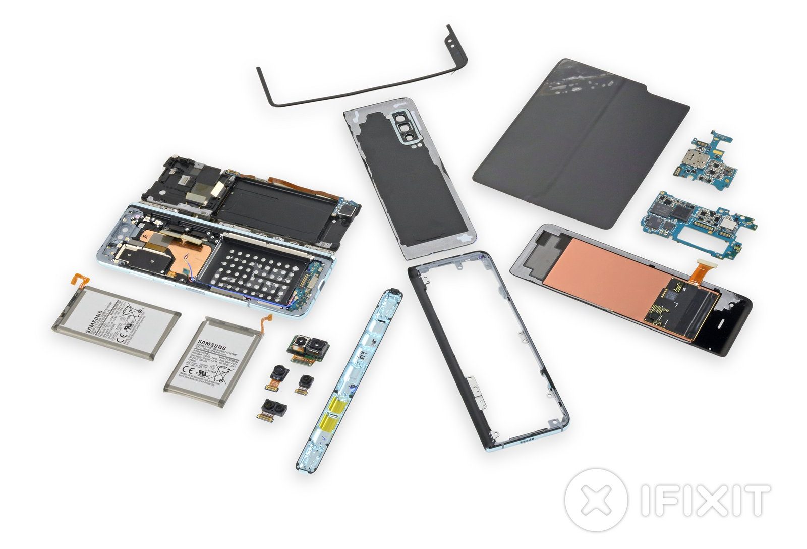
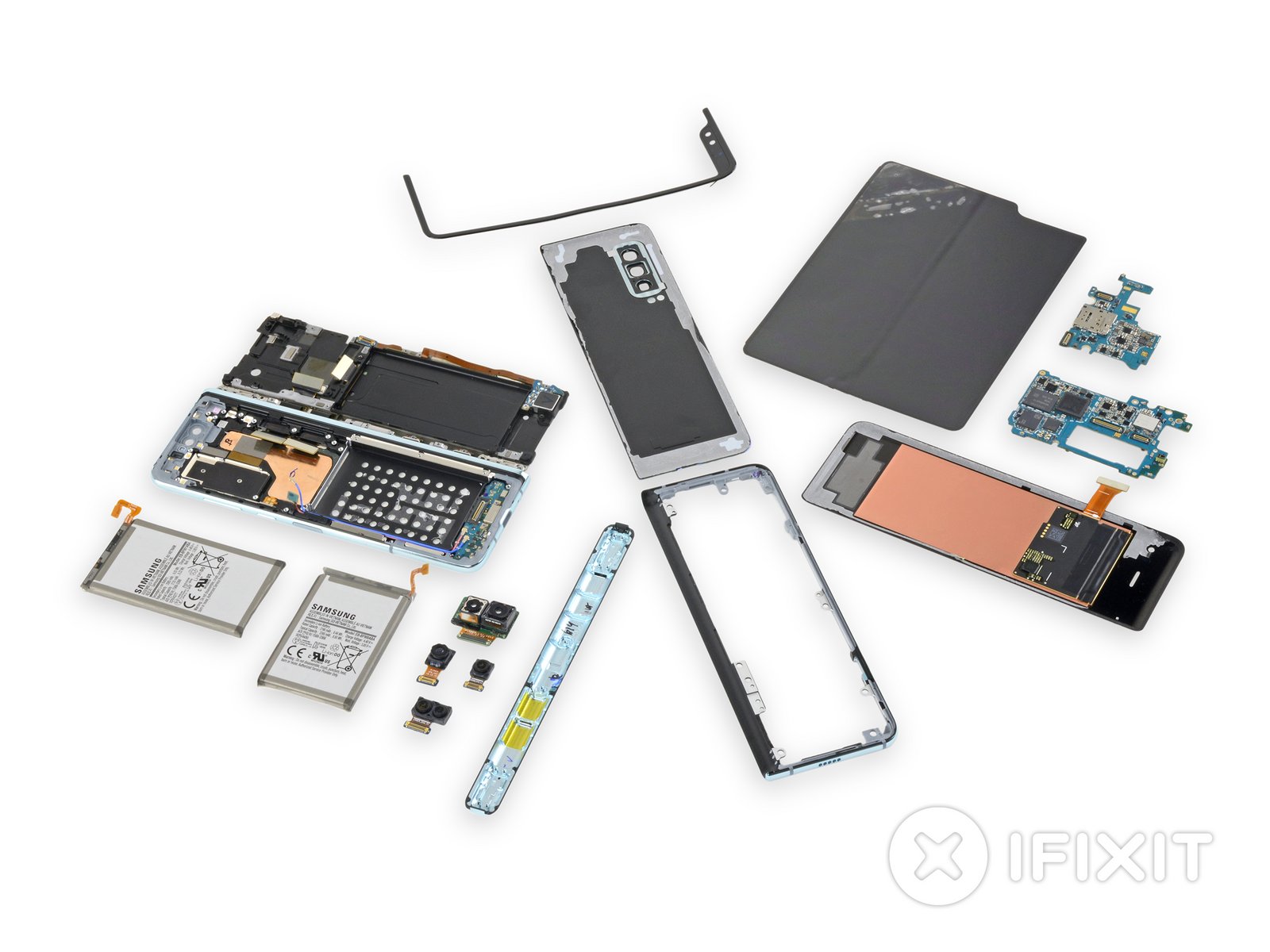
“Taylor Dixon” did a teardown of Samsung Galaxy Fold and reveals what’s inside for the rest of us.
Well, we’ve finally got the Samsung Galaxy Fold on our teardown table. This is, without question, an ambitious first-generation device—the idea of having both a smartphone and a tablet in your pocket at all times is pretty exciting! That said, a number of early reviewers had some durability issues with their review units, ultimately leading to a launch postponement. Are these temporary setbacks? Or are we headed for a full-blown AirPower-style product cancellation? We have no idea—we’re just here for a teardown.
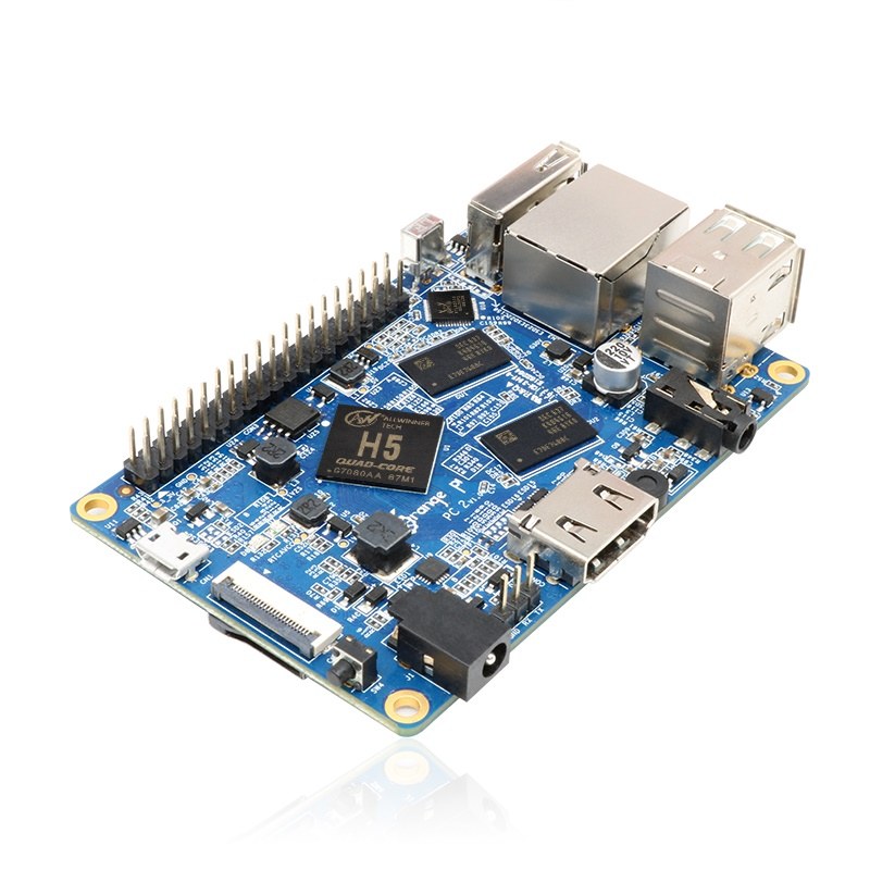
A few time has passed since the addition of Orange Pi PC 2 to the Orange Pi family of SBCs made by Shenzhen Xunlong Software CO., Limited and this successful and high capable board still sales like crazy at $36.65 from various distributors online.
Even though this 85×55mm board isn’t as cheap as the $4 VoCore2 Lite, its $36.65 price tag is justified by the hardware it packs inside. And, it also has almost same price as the $35 Raspberry Pi 3. Orange Pi PC 2 is a single-board quad-core 64-bit computer capable of running Android 4.4, Ubuntu, Debian, Banana Pi, and Raspberry Pi images. But let’s take a closer look at it’s features and specifications.
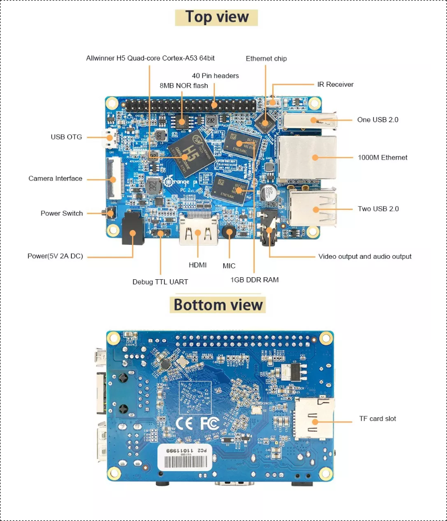
The board is equipped with 1GB DDR3 SDRAM memory, H5 High Performance Quad-core 64-bit Cortex-A53 processor and a standalone graphics chip (Mali 450). It supports camera input as well as HDMI output and it even has a physical power switch and IR receiver. It takes power using a separate power connector despite the fact that it has a micro-USB port. The absence of WiFi and Bluetooth is a slight turn-down but USB 2.0 ports can be used to add these features. The board also includes a Gigabit Ethernet port and three USB 2.0 ports.
Hardware specifications
CPU: Allwinner H5 64-bit Quadcore (Cortex-A53)
RAM: 1GB DDR3
GPU: Mali-450
Storage: 2MB NOR Flash, up to 64GB via MicroSD card
Connectivity: 2xUSB 2.0, 1xUSB 2.0 OTG, HDMI, 10/1000 RJ45, IR receiver, camera interface, 40-pin header
You need to get these accessories to start using your Orange Pi: TF card (minimum 8 GB), HDMI to HDMI lead or HDMI to DVI lead (for monitors with DVI input), AV video lead, DC power adapter, keyboard and mouse, plus Ethernet cable/USB WiFi and Audio lead as an option.
Prepare your TF card
Insert your TF card into your computer. The size of TF should be larger than the OS image size, generally 8GB or greater.
Format the TF card. (using this tool for Windows, and some commands for Linux)
Run fdisk –l /dev/sdx command to check the TF card node.
Run umount /dev/sdxx to unmount all the partitions of the TF card.
Run sudo fdisk /dev/sdx command to configure TF card. Use o command to delete all partition of TF card and use n command to add one new partition. Use w command to save change.
Run sudo mkfs.vfat /dev/sdx1 command to format the new created partition of TF card as FAT32.
(x should be replaced according to your TF card node)
Write the image file to the TF card using this software on Windows and this command on Linux: sudo dd bs=4M if=[path]/[imagename] of=/dev/sdx (x should be replaced according to your TF card node)
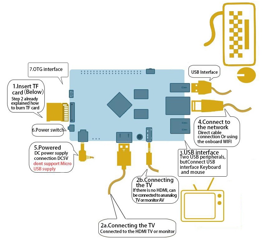
Set up your Orange Pi PC following the steps in the diagram
Shut down your board: You can use the GUI to shut down the Orange Pi PC2 safely or just run this command in the terminal: sudo halt or sudo shutdown –hnow This will shutdown the OrangePI safely, (just use the power key to turn off might damage the TF-cards file system). After that you can press the power key for 5 seconds to turn it off. Full guide and any updates on the OS image will be available here.
This is the main procedure to get started with OrangePi PC 2.
This open source SBC (single board computer) is a great option to start building IoT devices, DIY projects and for development purposes. You can use it as a mini-computer, a wireless server, music and video player,etc. You should remember that sky is the limit when it comes to open source boards.
The Orange Pi PC 2 is up for sale on www.banggood.com and you can get it now for $36.65.
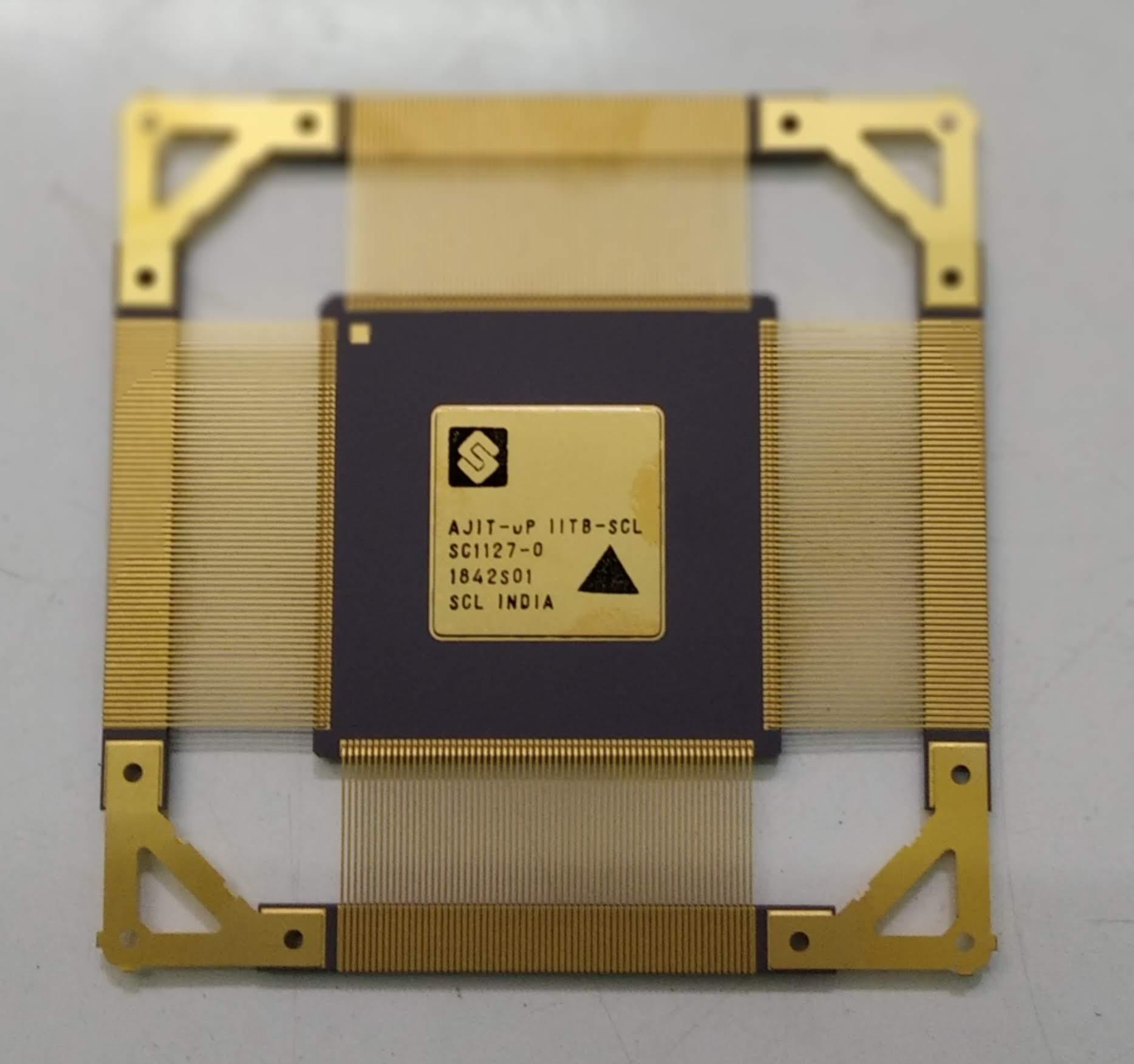
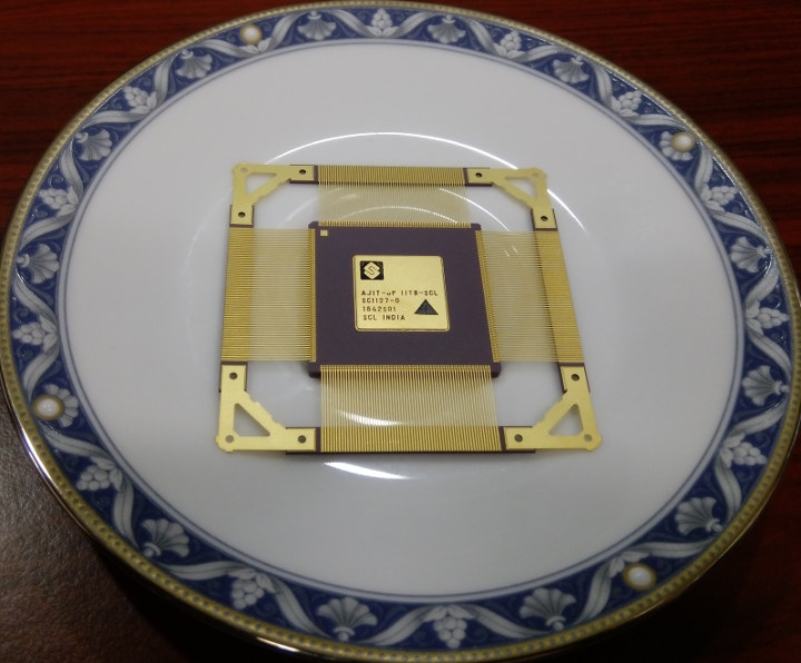
In this modern era, the electronics industry is incomplete without microprocessors. From daily household appliances to space exploration – microprocessors are accompanying us everywhere and making lives way easier. But, independently designing and manufacturing a processor is an extremely complicated task and done by only a few countries like the US, Italy, France, Japan, Taiwan, Singapore, Malaysia, etc. India was not in the list, that’s until recently IIT Bombay, one of India’s premier technology institute developed the country’s first-ever indigenously-built SPARC ISA architecture based microprocessor called AJIT, led by Prof. Madhav Desai.
A plate full of AJIT – India’s First-Ever Microprocessor
Here’s a quick introduction of microprocessor: A microprocessor is an IC comprises of millions or more transistors and function as the controlling unit of a micro-computer, fabricated on a small chip capable of performing ALU (Arithmetic Logical Unit) operations and communicating with the other devices connected to it. Microprocessor consists of an ALU, register array, and a control unit.
This project by IIT Bombay comes under the Government of India’s “Make In India” initiative which encourages both multinational and domestic companies to design and manufacture products within the country to make India a global manufacturing hub. The name “AJIT” is not an acronym and is derived from Sanskrit, meaning “Someone who has not been conquered“. As far as I could gather information, the AJIT microprocessor uses SPARC ISA architecture. SPARC (Scalable Processor Architecture) is a reduced instruction set computing (RISC) instruction set architecture (ISA) originally developed by Sun Microsystems.
This 32-bit microprocessor is clocked at around 70-120 MHz, features an arithmetic logic unit (ALU), a memory management unit, a floating point unit (FPU) for high-speed floating point operations, and also a hardware debugger unit. As per the researchers associated with development, a clock speed of 400-500MHz is obtainable in the next upgrade. AJIT is a 180nm technology-based chip, but the researchers plan to move to a 65nm process eventually. They published the tool AHIR-V2 which used in this project on GitHub.
AJIT is pretty cheap, it’ll cost only ₹100 (100 Indian Rupees) which is equivalent to $1.44. Unlike Shakti, which is India’s first-ever RISC-V architecture based microprocessor developed in collaboration with Bluespec, a US-based semiconductor tool design company, AJIT is truly indigenous. This microprocessor is not for smartphones or PCs, rather it is primarily designed to power India’s satellites for Indian Regional Navigation Satellite System (IRNSS) Program. One of the researchers of the project team stated,
We are planning to use AJIT in the receivers being developed for NAVIC or IRNSS, an indigenous navigation system for the Indian subcontinent
Though, some of the other applications include set-top boxes, control panels for automation systems, traffic light controllers or robotic systems.
To learn more on AJIT and the journey of India’s semiconductor industry, check this article at Research Matters. Also, you may check this and this Reddit posts.
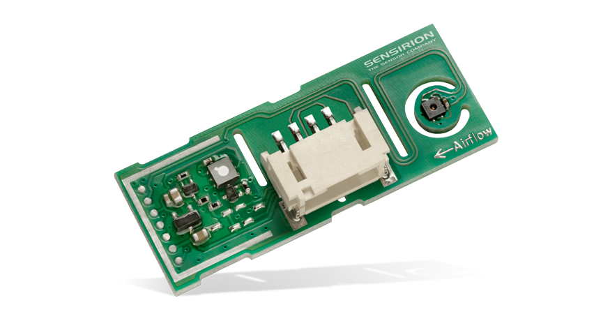
SensirionSVM30 Multi-Gas, Humidity, and Temperature Sensor Combo Module is ideal for measuring indoor air quality in devices such as air purifiers, air conditioners, and other air treatment products. The SVM30 combo module contains an SGP30 gas sensor as well as an SHTC1 humidity and temperature sensor. The SGP30 multi-pixel gas sensor combines multiple metal-oxide sensing elements on one chip. This means a total VOC signal (tVOC) and a CO2 equivalent signal (CO2eq) can be measured through that one sensor chip. Sensirion SVM30 provides a solution to design challenges like thermal decoupling of the sensors and compensation of humidity cross-sensitivity.
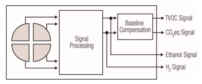
Block Diagram
SVM30 Block Diagram
The gas and RH/T sensor components on the SVM30 are designed with Sensirion’s CMOSens® Technology. This technology offers a complete sensor system on a single chip, including the sensing elements, analog and digital signal processing, analog-to-digital converter (ADC), calibration and data memory, and a digital communication interface supporting I2C standard mode. The sensing element also offers robustness against contamination by siloxanes present in real-world applications, enabling long-term stability and low drift.
Features
Measures indoor air quality parameters tVOC, CO2eq, relative humidity, and temperature
Fully factory calibrated and tested
Digital I2C interface
Automatic baseline compensation and humidity compensation of MOX gas sensor
Long-term stability and reliability
Specifications
4.5V to 5.5V supply voltage
49mA Avg. current
Package: 39mm x 15mm x 6.5mm PCB
1s sampling rate
-20°C to +85°C operating temperature range
±1°C Typ. temperature accuracy
0% to 100% RH humidity measurement range
±5% RH humidity accuracy
Output range: TVOC – 0 to 60,000ppb; CO2eq – 0 to 60,000ppm
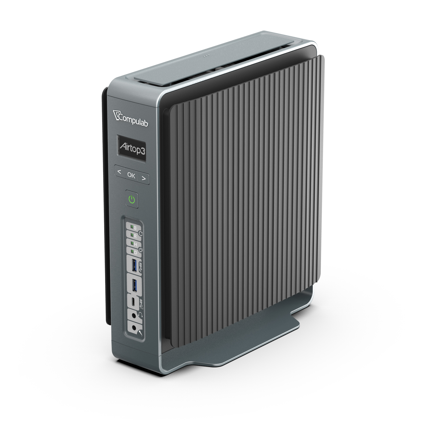
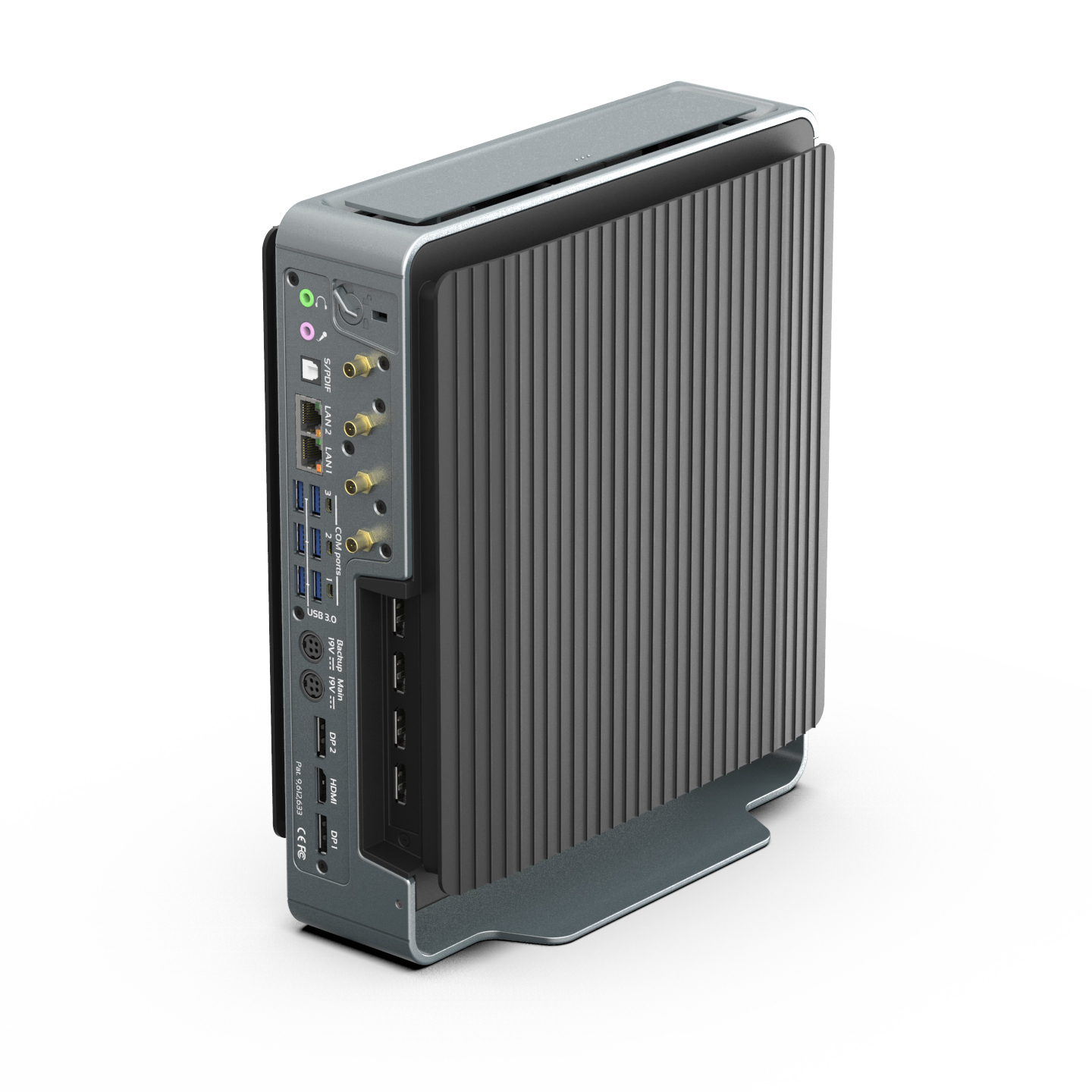
Compulab is introducing Airtop3 – a ruggedized small-form-factor fanless IoT edge server powered by an 8-core Intel® Core™ i9-9900K Processor and Nvidia Quadro RTX 4000, both passively cooled using Compulab’s Natural Airflow technology. With a footprint of just 7.5 liters, Airtop3 can passively dissipate up to 300W and operate at a wide temperature range of -40°C to 70°C. Airtop3 ships with a 5 year warranty.
Fanless Core i9 9900K and Quadro RTX 4000
IoT edge server can reduce processing latency, network bandwidth requirements and TCO, provided that it is sufficiently powerful, robust and easy to deploy.
Airtop3 presents a unique value proposition for edge computing in harsh environments:
Exceptionally high performance – 8-core, up to 5 GHz Intel Core™ i9-9900K or Intel Xeon coupled with Nvidia Quadro RTX or GeForce GTX GPU and high RAM capacity up to 128 GB
Rich storage, networking and I/O, each can be enhanced thanks to Airtop3’s modular design
Passive cooling across wide temperature range and a rugged all-aluminium small-form-factor housing
Maintenance-free design, tool-free serviceability and advanced monitoring and diagnostics provisions
“Apparently, the appetite for performance at the IoT edge knows no boundaries”
said Irad Stavi, Chief product officer at Compulab.
“We are seeing remarkable performance gains in the latest generation of CPUs and GPUs, but with great power comes greater power consumption. However, our engineers were able to improve the thermal headroom of Airtop3’s Natural Airflow cooling by over 30% so there was no need to settle for low power chips. This makes Airtop3 a small-form-factor fanless IoT edge server with unprecedented performance.”
“Benchmarks indicate that Airtop3 is nearly twice as powerful as Airtop2”
said Yuval Sela, Airtop hardware architect.
“To achieve that, power delivery in Airtop3 is completely revamped and can now support the most powerful Intel 9th generation Core CPUs and even 160W NVIDIA RTX GPU.”
Airtop3 performance and features
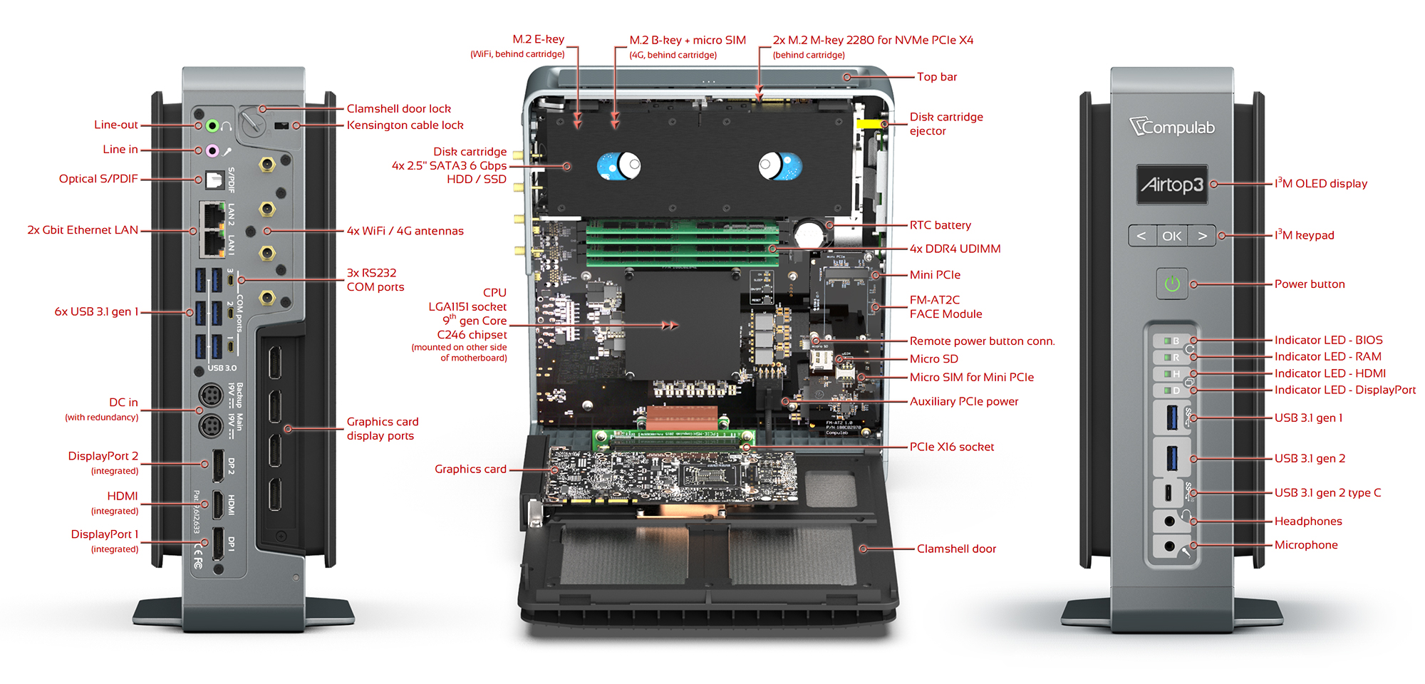
Airtop3 supports 9th Generation Intel® Core™ i9 Processors and future Intel® Xeon® E Processors, including the highest power 95W Core i9-9900K. The maximum RAM capacity is 128 GB DDR4-2666. Standard storage is comprised of 6 devices – two NVMe SSDs – up to 2 TB each and four 2.5” SATA 3 HDD/SSD with RAID support. Standard networking includes two GbE ports and support for Wi-Fi 802.11ac and 4G modem. Standard I/O includes 3 4K displays, 6 USB 3.1 ports, 3 RS232 and audio. This feature set may be satisfactory in some cases, but IoT has many specialized applications – deep learning may require a discrete GPU, automotive applications often require high capacity of high-speed storage, machine vision usually utilizes integrated PoE ports. For these use cases and other, Airtop3 offers functional enhancements.
Enhanced graphics
Airtop3 has a PCIe x16 (PEG) slot with Natural Airflow passive cooling that supports up to 160W Quadro RTX 4000 graphics card. This powerful CPU + GPU setup is effective for low latency edge analytics workloads involving image recognition, machine learning or inferencing.
The four displays of the graphics card can work in tandem with the integrated graphics for a total of seven 4K displays.
Enhanced storage
The standard two NVMe cards and four 2.5” SATA SSD/HDD support up to 20 GB with RST or software RAID and are passively cooled in a dedicated thermal zone.
Storage can be enhanced using Airtop3’s NVM3 card installed in the PEG slot. NVM3 supports additional three NVMe cards up to NF1 30110 form factor.
NVM3 enables remarkable data rate of over 9500 MBps and increases max storage capacity to over 60 TB. It allows installing SSDs with power loss protection (PLP).
Enhanced networking
Dual Gbit Ethernet (Intel i210 + Intel i219) and optional WiFi 802.11ac + 4G/LTE modem are available as a standard. For higher bandwidth, dual 10 GbE card can be installed in the PEG slot. Extra networking capabilities can be added using a FACE Module
FM-PoE adds 4 GbE ports, each with 802.3af PoE source which simplifies setups involving IP cameras
FM-OPLN adds 2 GbE SFP+ optical LAN ports which enables longer range, better immunity and higher security
Airtop3 Block Diagram
Cooling, durability, modularity and monitoring
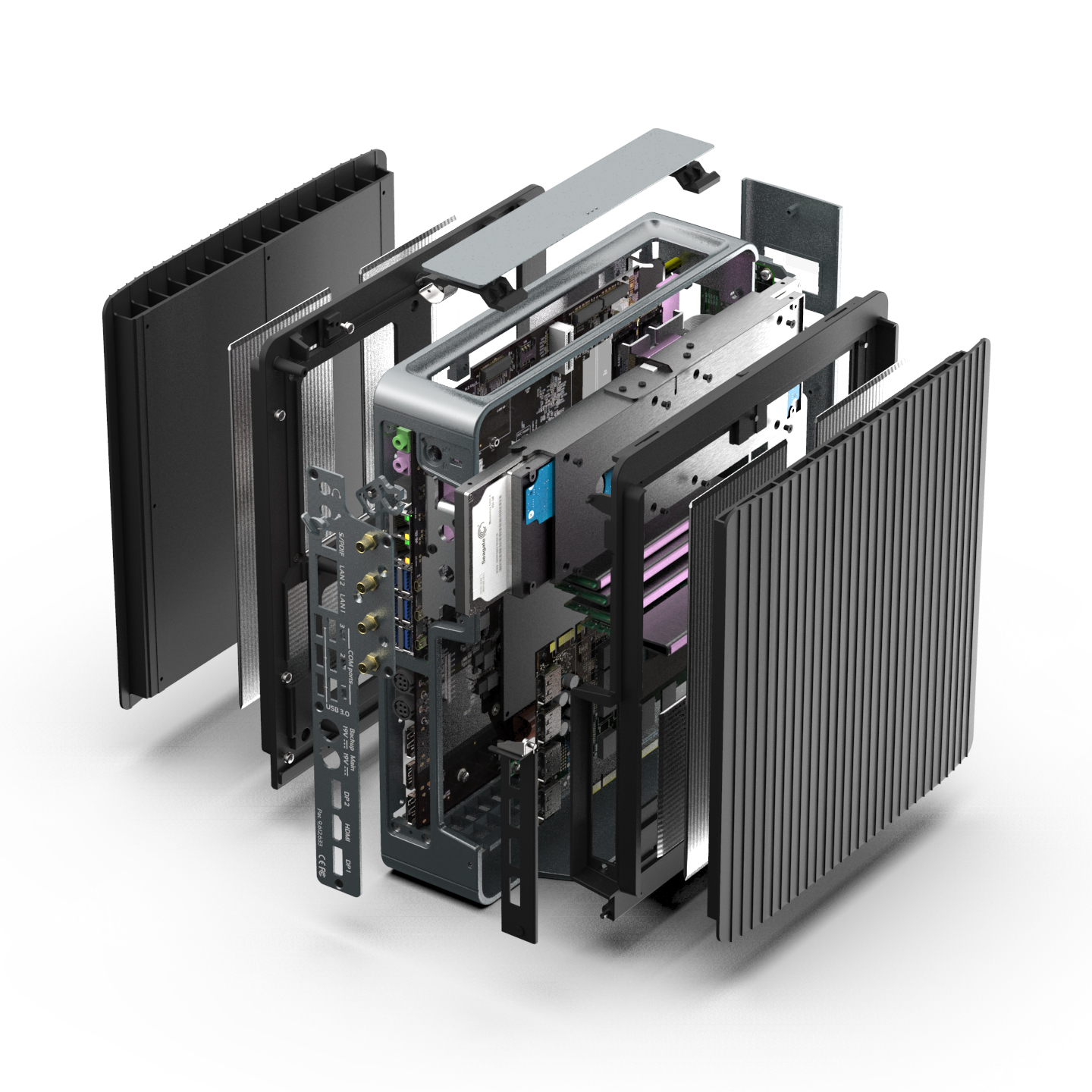
Airtop3 cooling is based on Compulab’s Natural Airflow technology that stimulates airflow without moving parts – by the waste heat of the 3 major heat sources (CPU, GPU and storage devices) each having a dedicated thermal zone.
The 7.5 liter housing is all-aluminium made of die-cast and extruded parts with precision machining for seamless fit, shock and vibration resistance.
Airtop3 supports Compulab FACE Modules (Function And Connectivity Extension Modules) which enable various application specific networking and I/O capabilities. A new FACE Module designed specifically for Airtop3 – FM-AT3 adds 2x USB 3.1 gen 2 (one USB type-C) + 1x USB 3.1 gen 1, front audio jacks, mini-PCIe socket with SIM card, micro-SD and diagnostics LEDs for troubleshooting RAM, BIOS and display issues.
It is very easy to install RAM and storage devices in Airtop3 thanks to the clamshell tool-free opening.
Airtop3 includes the I3M OLED display – for displaying vital runtime information including clock rate, temperature and power consumption.
Price and availability
The Airtop3 is available starting at $999 for the barebone (no RAM) Celeron model and $1,639 for the Core i9-9900K model with 8GB RAM. Build-to-order versions require six weeks lead time. More information may be found in Compulab’s Airtop3 announcement, as well as on the product page and shopping page.
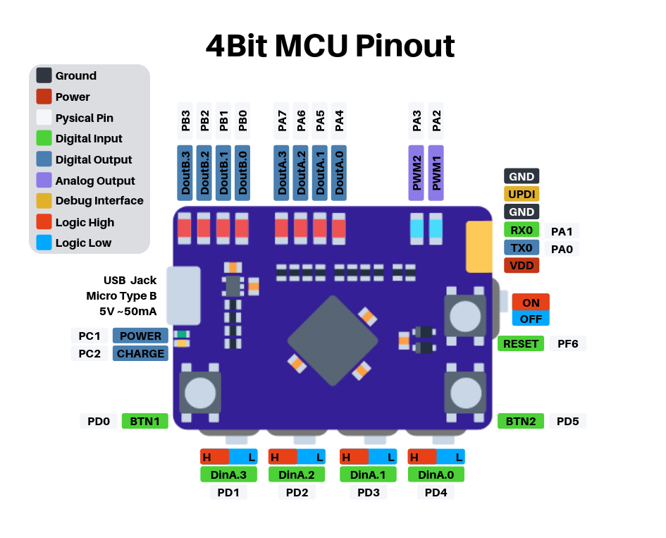
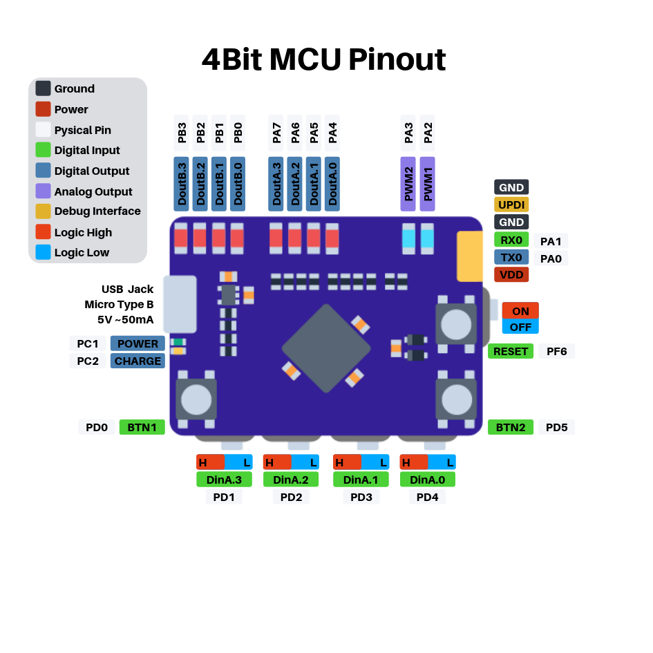
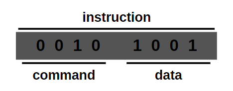
BIT4 is a 4Bit microcontroller – fully programmable with only three buttons.
The BIT4 microcontroller has 256 Bytes of programm memory, split in 16 pages with each 16 instructions. A instruction is 8bit wide and consists of an command and data:
To enter the programming mode, hold BTN2 down, press the RESET button once and then release BTN2. In programming mode, step through the instructions with BTN2. When going to a new instruction, the leds will show the current address for a fraktion of a second. With BTN1 the value of the command and data of the current instruction can be changed. When stepping to a new address with BTN2, the instuction of the address above gets saved in the EEPROM. At the end, press RESET to leave the programming mode and to start the programm execution.
It detects stationary and moving people just like a PIR, but it can do that also behind doors and thin walls, by taking advantage of the Doppler effect. By Boris Landoni @ open-electronics.org:
The detection of people, animals and hot bodies in general has been done for years using passive infrared radars, also known as PIR, which work by placing a pyroelectric sensor, so a heat sensor, behind a Fresnel lens, which has the ability to focus on just one point the infrared rays coming from the frontally detected heat, emitted by moving objects within a certain angle.
PIR sensors cover a wide array and variety of applications and represent by now a low-cost solution to protect ourselves from home invasion, automatically activate utilizers when moving people are detected etc., although they have the limitation to be able to detect only whatever can be seen: they cannot detect, even at a short distance, people moving behind doors and windows, so if we employ them in a home security system, they will only be activated when the intruder is already inside the room where the sensors are installed.
In order to have a preemptive protection, we can make use of radiofrequency sensors and, to be precise, microwave sensors, because they can detect people behind doors and even walls as long as they are not too thick or made of reinforced concrete or metal, or walls containing metal plaster reinforcement grids (for bladder walls) or cavity for sliding doors such as Scrigno.
Microwave Presence detector works using Doppler Effect – [Link]
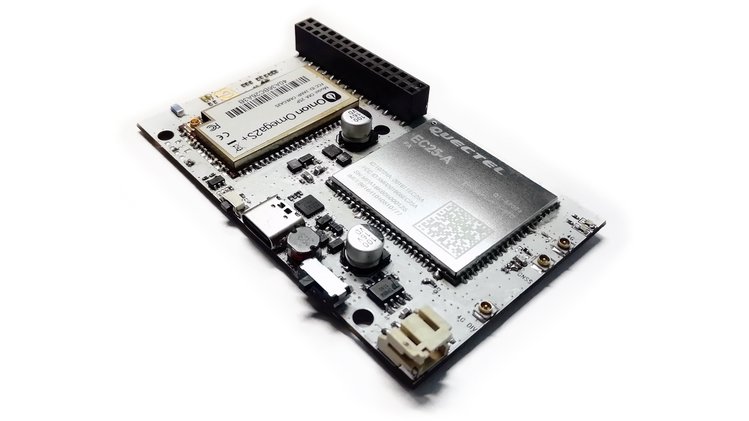
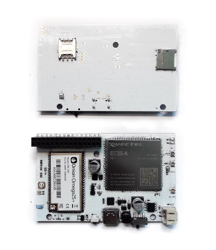
The Omega2 LTE is a Linux IoT computer with Wi-Fi and LTE cellular connectivity.
Effortlessly deploy your existing IoT applications in remote areas and no longer be limited by the range of Wi-Fi networks. The Linux network stack makes the switch between WiFi and cellular data seamless to user applications.
Take your existing NodeJS or Python IoT project outside the building with ZERO effort!
The Omega2 LTE has all the hardware you need for:
Remote sensor applications – as a hub or end-node
Real-time asset tracking
LTE Hotspot – share the high-speed LTE data connection with IoT devices, laptops, and tablets
Now with GNSS Support
On top of that, the Omega2 LTE also has GNSS global positioning capabilities, further extending the possible use cases to include real-time asset and fleet tracking.
Compatible with GPS, GLONASS, Galileo, Beidou, and other regional systems
Easily report geopositioning and other data to remote servers using the LTE data connection
Self-contained and Battery Powered
Omega2 LTE is a self-contained device that is smaller than a standard breadboard, making it a great form-factor for use in any IoT project. Just add LTE antennas and power.
It’s flexible when it comes to power: you can provide power from any USB port or with a LiPo battery. Connected batteries will automatically recharge when USB power is present, and will act as a back-up power supply if USB power is not stable.
The Omega2 LTE features a MediaTek MT7688 MIPS WiSoC, 128Mb DDR2 RAM, and 32Mb of Flash.
Wireless Networking Capabilities
The Omega2 LTE specializes in wireless networking, sporting 4G LTE connectivity and Wi-Fi capabilities, making it ideal for outdoor and remote sensor hub applications.
The Wi-Fi interface can simultaneously host its own Wi-Fi access point and connect to existing Wi-Fi networks
It enables uses cases that are not limited by the range of Wi-Fi networks since the 4G LTE data connection provides internet connectivity as long as there is cellular signal
The LTE data connection can also be shared through the Omega’s Wi-Fi access point or even through ethernet using the Ethernet Expansion
The Omega2 family
Omega2 LTE is the latest addition to the Omega2 family and is based on the Omega2S module so it builds on all of the work we’ve done over the past three years since launching the Omega2. That means it’s an all-in-one device that features the standard Omega2 30-pin header, and it comes pre-loaded with the OpenWRT Linux OS. Also, it’s compatible with our existing eco-system of Omega2 Expansions. OnionOS provides an intuitive user interface through the browser with no installation required. Write code, run commands, and use apps to interact with your Omega2 LTE.
“Effortlessly deploy your existing IoT applications in remote areas and no longer be limited by the range of Wi-Fi networks. The Linux network stack makes the switch between WiFi and cellular data seamless to user applications.”
Upgraded USB port for power and serial command line access to USB Type-C
Does not feature 8 GB eMMC – Instead the operating System runs on on internal storage of Omega2S+ module and has a MicroSD slot for extending storage space
Added 4G LTE network status and activity LEDs – Does not have a RGB Notification LED
Rectangular, enclosure friendly board layout instead of the the signature Onion three-corner-cut design.
Still features 30-pin I/O header and support for Omega2 Expansions
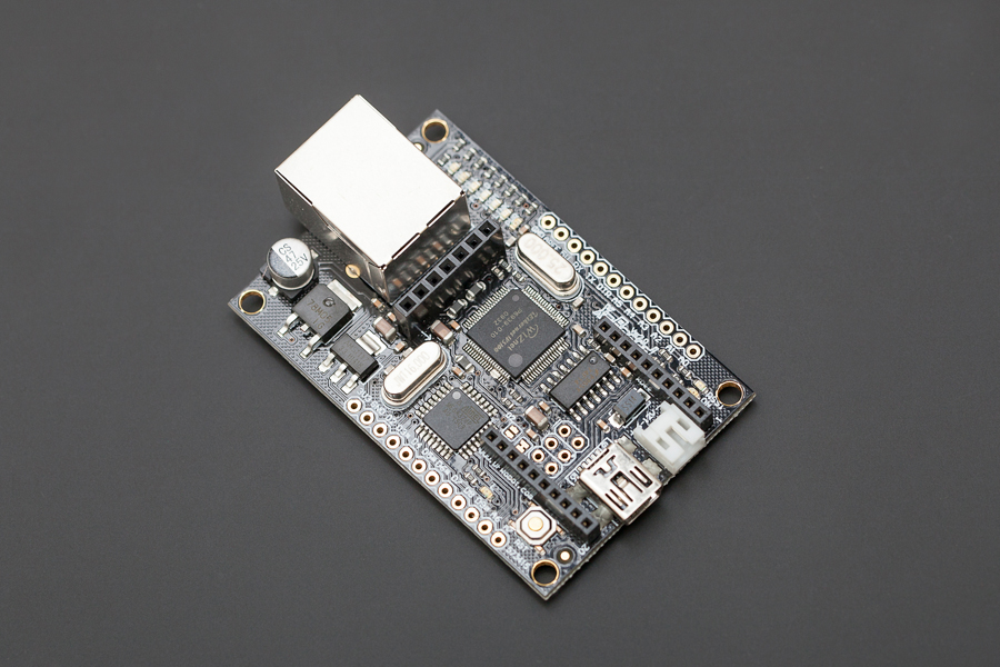
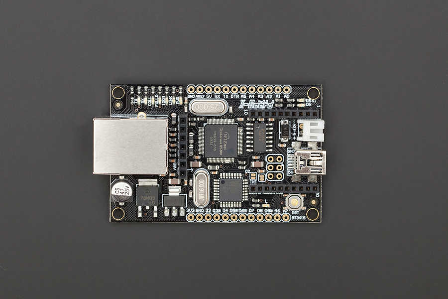
This is Version 2.0 of the Xboard. The main improvement is that it now operates at 5V, making it compatible with most sensors and I2C protocol without the need of a voltage level converter.
The XBoard is a unique Arduino board which features a WIZnet ethernet port, an XBee socket, and an ATMega328. This board will add wireless XBee control as well as internet connectivity to your projects. It’s great for anything from home automation to robot control. The possibilities are endless!
It has 8 Analog I/O pins and 8 digital pins, 4 of which have PWM (indicated by an asterisk). It is compatible with all XBee modules, and also comes with an integrated socket for APC220 RF Module or DF-Bluetooth Module. The XBoard can be programmed via an FTDI programmer or via the ICSP header. Power is provided through a Mini USB connector. You can setup a web server through which you may communicate with a remote Arduino using XBee radios, bluetooth or APC modules.
Specification
MCU:Atmega328P low voltage version (16Mhz)
Ethernet:WIZ5100
Arduino Uno bootloader
Supply voltage:5~12v
Output voltage:5v/3.3v
Digital IO: 8
Analog In: 8
Envionment Friendly: Rohs Compliance
more information can be found on the following documents:
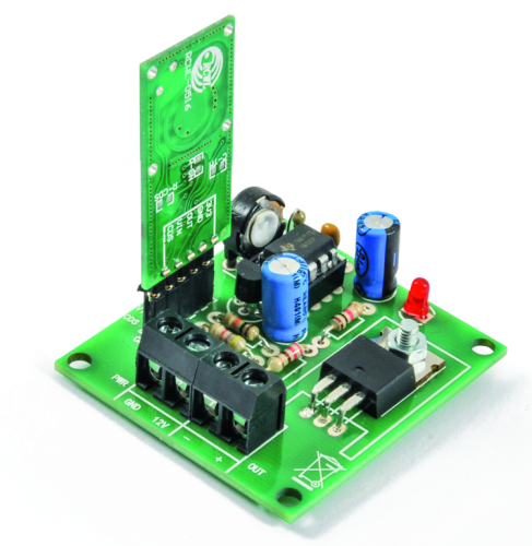
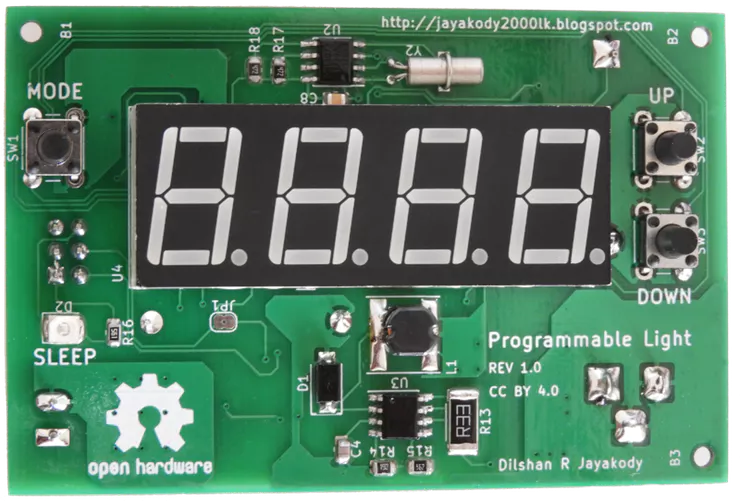
A low-cost, easy-to-build, high-power LED controller with a built-in programmable timer.
This project is published with author’s permission and uploaded through our Upload Project
The main objective of this project is to design a maintenance free and low-cost light which automatically turns on and off at the predetermined time of the day.
This kind of light helps to reduce power waste and save energy. In these days people have a habit to turn on at least one light of there residence if they are going out of home for a couple of days. Then lights start to blazing all day and night and waste lots of energy. If we can use this programmable light, then we can configure it to turn on every night and turn off at the next day by without any human involvement.
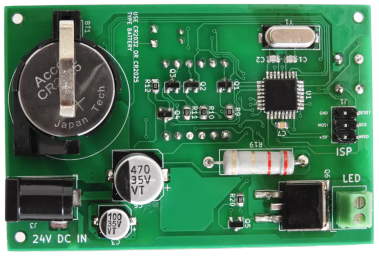
The core component of this programmable light is ATmega8 low power CMOS microcontroller. The main reason to select this microcontroller is it’s lower cost and higher availability. Except for the above two reasons this microcontroller also bundled with a rich set of peripherals which including 23 GPIOs, 3 independent timers, Two-wire serial interface, EEPROM, etc.
Apart from ATmega8 microcontroller, this system uses DS1307 real time clock to maintain system time. Like ATmega8, DS1307 is also a very popular RTC in the market.
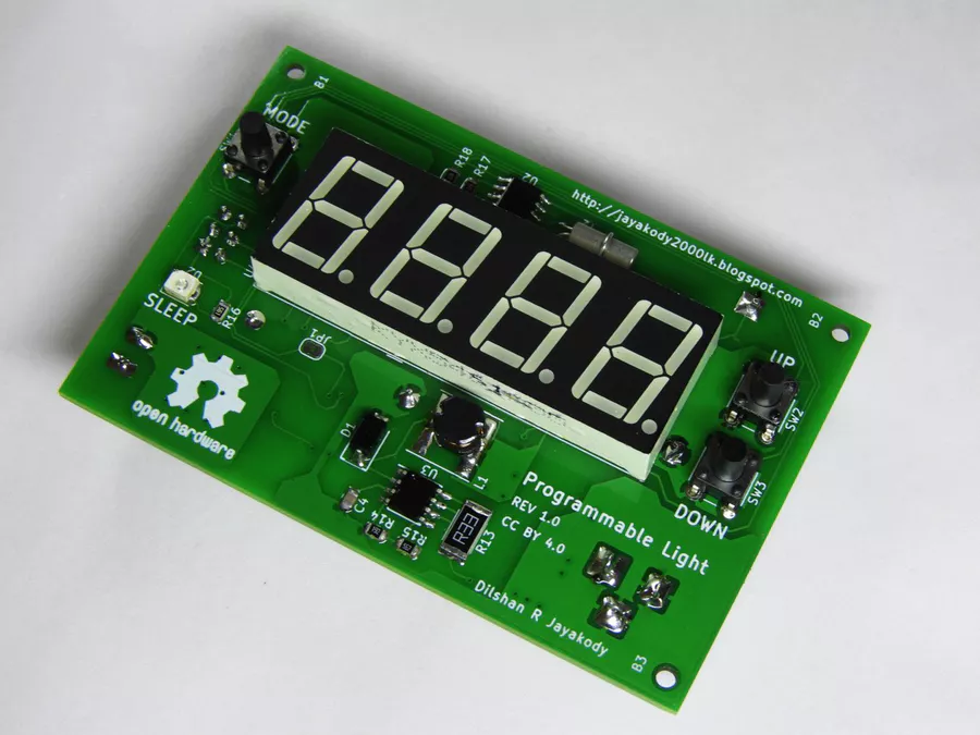
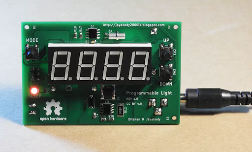
Fig 1: Front side of the programmable light controller
This controller is designed to work with a 24V DC power supply. The main reason to select 24V is that most of the medium power LED modules in the market are designed to work with that voltage. During my search all the medium power LED modules which I found are designed to work with 20V – 28V range. Out of those LED modules, the majority of modules are rated for 24V input.
For this circuit, the recommended power supply is 24V 1.5 A portable switch mode power supply. Except for the LED driver stage the all other parts of this light controller is designed to work with 5V. MC34063 DC-to-DC converter is used to supply 5V to those components.
Fig 2: Back side of the programmable light controller
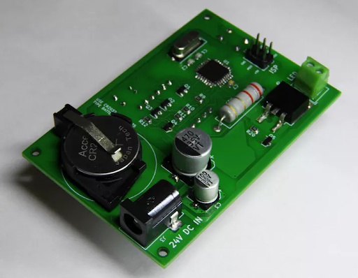
To reduce the size I design this system using surface-mounted components, but this system can also build using through-hole type components. At the prototype stages, I build this system entirely on a breadboard using through-hole type parts.
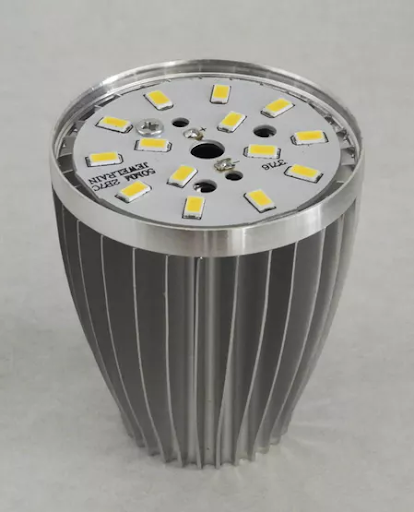
To build 7W light, I used LED lamp parts available in the market which including Warm white 7W LED panel, aluminum lamp shell (heatsink) and diffusing cap (lamp cover).
Construction
As mentioned previously this programmable light can build in many ways which including using PCB, Veroboard, breadboard, etc. The most favored way to construct this system is using a PCB.
The PCB design which I provide is based on 2 layers and because of that, it’s advised to build this PCB using some PCB fabrication service.
Fig 3: All the components of this board are soldered using conventional soldering iron.
After fabricating PCB, you can start soldering the components into it. At first, try to solder SMD ICs. After soldering all 3 ICs next start with small SMD components such as resistors, capacitors and SOT-23 transistors. I highly suggest installing seven segment display, DC jack base, battery clips and terminals header at the last stages of the soldering.
Upload firmware into the system
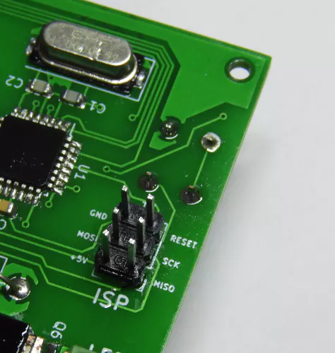
Once all the components are assembled the next task is to feed firmware into the microcontroller. To upload the firmware the most recommended method is to use AVR in-circuit programming (ISP) compliant adapter.
This system is designed to work with standard 6-pin AVR ISP interface and there are plenty of programmers are available for this interface.
During my prototype assembly, I used aUSBasp programmer to flash the microcontroller with firmware.
Fig 4: ISP header to connect programmers.
During the firmware upload process pays extra attention to ATMega8 fuse settings. To get intended results low-fuse byte should set to 0xEF and high-fuse byte should set to 0xD9. For more details refer project documentation at the GitHub.
While using ISP make sure to disconnect the 24V power supply from the system.
LED module
After uploading firmware, the only remaining task is to connect the LED module into the controller.
Before soldering 7W LED module, fix it to the provided heatsink. To improve thermal transfer make sure to apply thermal grease between the LED module and heatsink.
Fig 5: Partially assembled LED module.
While LED lighting for long hours its temperature increase up to 70°C – 80°C. Because of this, make sure to take necessary action(s) to isolate the LED wire line with temperature. To overcome this, in prototype build I drive this wire through a high-temperature resistant Basalt sleeve.
Using the light controller
At the first power up light controller starts with default settings. To modify those settings hold down “MODE” button for a few seconds and then it opens the System menu.
System menu consists of 4 options such as “SYS”, “ON”, “OFF” and “—”. You can modify the value associated with each option by pressing the “MODE” button. In System menu press “UP” or “DOWN” buttons to navigate over the available modes.
Fig 6: Light controller in idle state.
In “SYS” mode user can change the system time. Likewise in “ON” and “OFF” modes, the user can set the light on and off times respectively.
To leave the System menu, press the “MODE” button in “—” mode.
The light controller firmware is designed to switch to the idle state if the user is not involved with the system for a long period of time. In the idle state, seven segment display of the light controller is not active. In most occasions SLEEP indicator also got activate in an idle state.
The light controller project which described in this article is a certified open hardware project. All the design files and firmware source files of this project are available to download at GitHub.
The compiled firmware and PCB Gerber files are also available to download at the GitHub release page.
All the content of this project are distributed under the terms of the following license:

![Orange Pi PC 2 – Quad Core 64bit Linux and Android mini PC [Getting Start Guide]](https://www.electronics-lab.com/wp-content/uploads/2019/04/orange-pi-pc2-board-18298-64-B-e1556126351871.jpg)