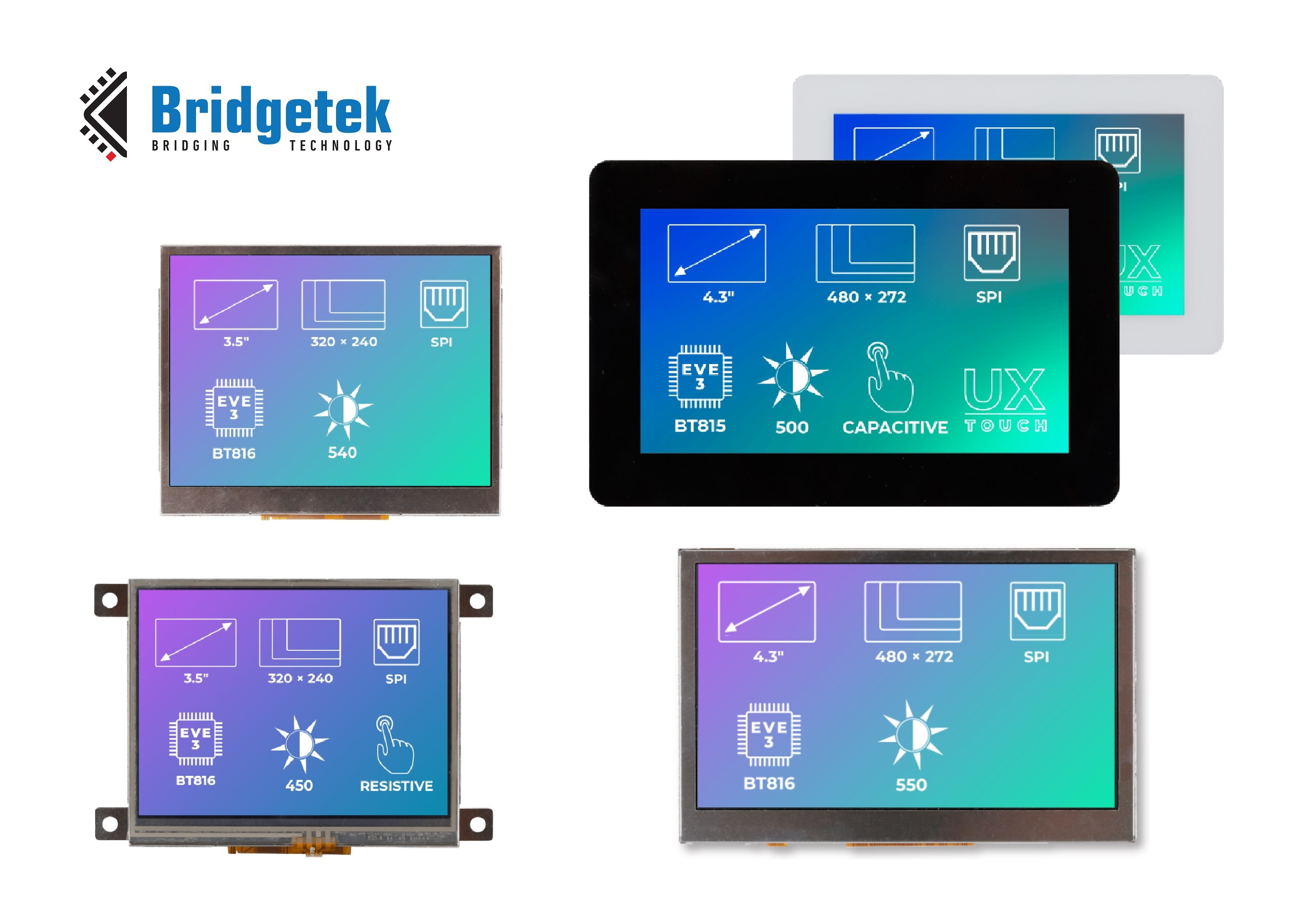
In order to broaden the appeal of its advanced graphics controller ICs in the emerging Internet of Things (IoT) sector, Bridgetek has entered into a three-way collaborative partnership with IoT development experts Zerynth and advanced display solutions provider Riverdi. Through cooperation between these companies’ engineering teams and drawing on their respective skillsets, customers will be better able to implement next generation smart building systems and Industry 4.0 ready factory automation equipment.
Benefiting from Bridgetek’s BT81x series devices, which incorporate the company’s multi-award winning Embedded Video Engine (EVE) technology, along with Riverdi’s touch-enabled display modules plus Zerynth’s IoT programming platform and its supporting libraries, this partnership will provide a compelling hardware/software offering that dramatically accelerates system deployments. EVE’s pioneering object-oriented architecture means that sophisticated human-machine interfaces (HMIs) can be constructed while only using minimal microcontroller and memory capacity, thus saving board real estate and curbing power consumption demands. Likewise, Zerynth’s Python-based programming platform keeps software engineering overheads down and is optimized specifically for resource-constrained IoT applications. This will enable the numerous Riverdi-supplied Wi-Fi/Bluetooth-compliant EVE HMI units within an IoT monitoring or control system to connect up to the cloud network and thereby utilize various cloud services.
The IoT presents huge opportunities for Bridgetek in terms of further automation of our living/working spaces and our factories. Bringing together proprietary EVE technology with the expertise of Zerynth and Riverdi means we now have a multifaceted solution to address these opportunities – covering all aspects from the chip level and board level right through to the firmware,
explain Lee Chee Ee, Head of Product Development at Bridgetek.
About Zerynth
Zerynth supplies the tools needed to develop IoT solutions. It simplifies the IoT development process by providing an easy and efficient way to program the most popular 32-bit microcontrollers in Python and connect them to cloud infrastructure, with the highest levels security. The company is headquartered in New York, with an R&D facility in Pisa, Italy, plus support from a global sales team. It is helping thousands of developers around the world to develop new IoT products and Industry 4.0 applications, with reduced costs and improved time-to-market. For more information go to https://www.zerynth.com
About Riverdi
Established in 2012, Riverdi brings high-quality customizable display solutions to the global market. Since its inception, the company has kept one dream in sight, to become the leading intelligent display manufacturer. With hundreds of thousands of displays sold all over the world, this dream is fast becoming a reality. For more information go to https://riverdi.com
About Bridgetek
Founded in 2016, Bridgetek supplies highly advanced ICs and board level products to meet the exacting demands of a constantly evolving global technology landscape. The company’s Embedded Video Engine (EVE) graphic controller ICs each integrate display, audio and touch functionality onto a single chip, thereby dramatically reducing in the time period and bill-of-materials costs associated with developing next generation Human Machine Interface (HMI) systems. These are complemented by its highly-differentiated, speed-optimized microcontroller units (MCUs) with augmented connectivity features.
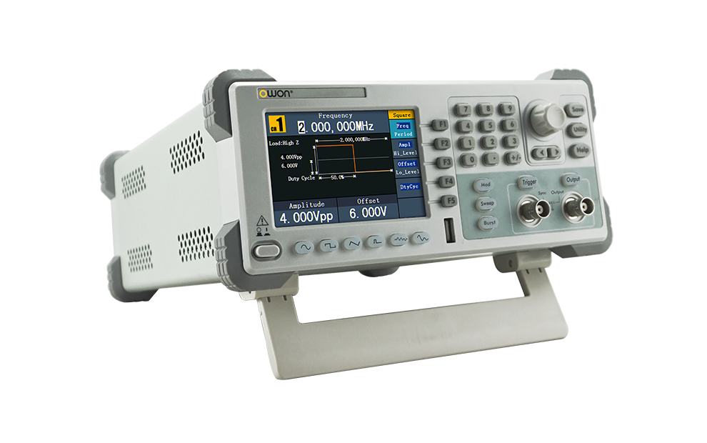
OWON multi-function waveform generator, working as arbitrary waveform generator, and function generator 2 in 1 provides stable, accurate, and pure DDS signal sources. Its user-friendly UI, together with keyboard layout brings brand-new user experience into the current market.
Features
Advanced DDS technology, upto 10MHz frequency output
125MS/s sample rate, and 1μHz frequency resolution
Vertical Resolution : 14 bits, and 8K arb waveform length
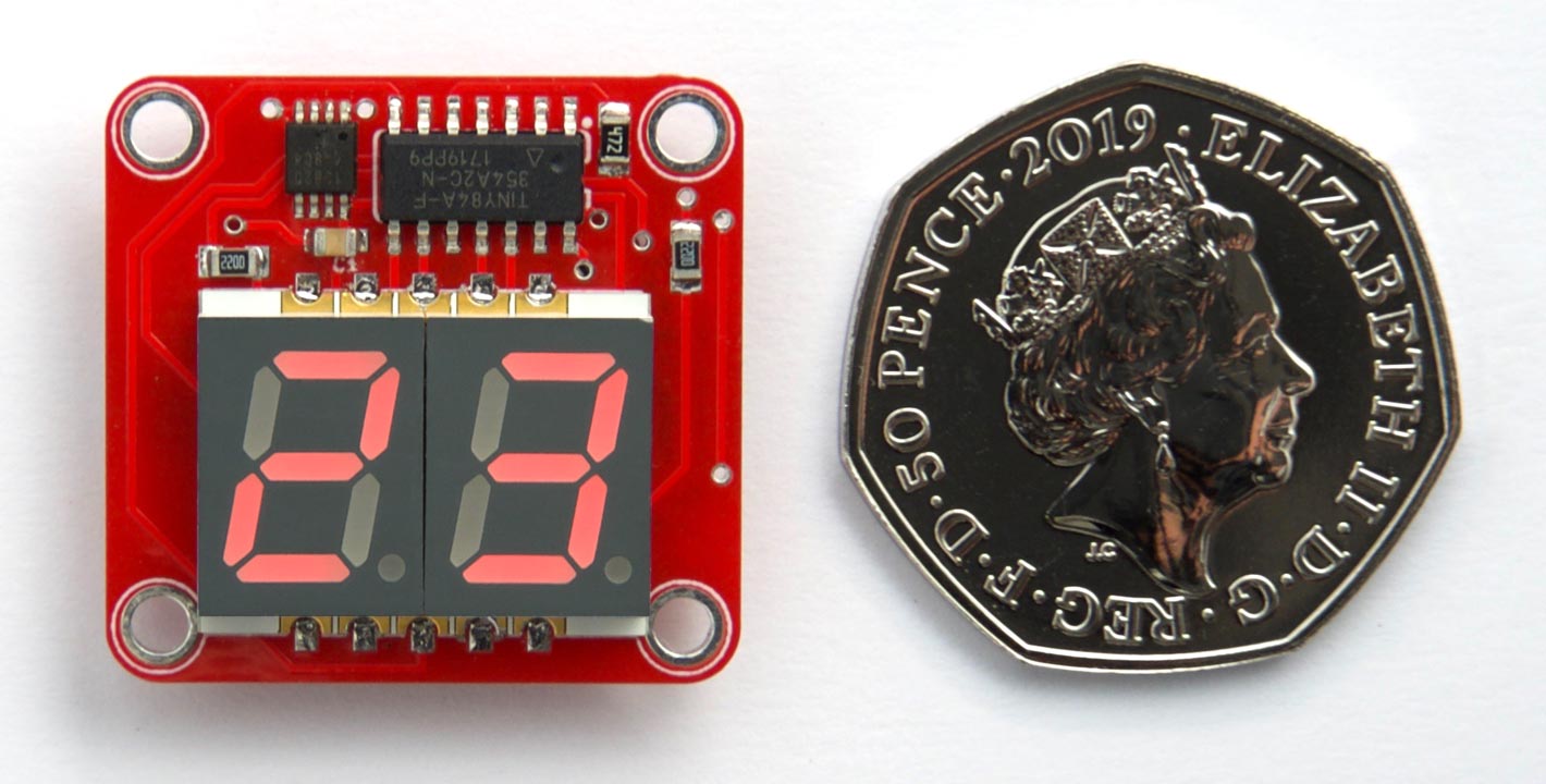
David Johnson-Davies shared another nice tiny project. This time is a two digit thermometer based on ATtiny84 and DS12B20 1-Wire temperature sensor.
It uses a DS12B20 1-Wire temperature sensor, and an ATtiny84 to drive the display and read the sensor. It’s just over 25mm square; about the size of a British 50 pence piece.
The two-digit thermometer is designed so it could be put in a waterproof case outside the window, to show the outside temperature in all weathers. To conserve power the thermometer flashes the temperature every 24 seconds, and then goes to sleep, and it achieves a battery life of about a year with a CR2032 button cell.
The thermometer can display temperatures between -19°C and 99°C. To display temperatures between -10°C and -19°C the left-hand display is used to display “-1”. Outside this range it displays ‘Lo’ for temperatures below -19°C or ‘Hi’ for temperatures above 99°C. If you live in a part of the world where temperatures regularly reach below -19°C you could change it to light the decimal points to indicate negative temperatures.
Two-Digit Thermometer using ATtiny84 and a DS12B20 – [Link]
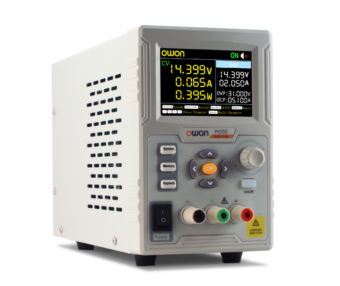
OWON P4603 Linear DC power supply newly launched with small body, lighter weight, easier to carry. Single channel, competitive unit price. With high resolution 1mV/1mA, 3.7 inch large TFT LCD display, 180W maximum output power. Low ripple and noise can meet the requirement for high accuracy testing. It can save up to 5 sets of parameters for easy recall. It can be used in mobile / laptop repair, PCB / Motor testing and battery charging. With Over voltage protection, Over current protection, over temperature protection and short circuit protection.
Features
Small body for easy carry
180W maximum output power
High resolution: 1mV / 1mA
Low ripple/noise
Over voltage/over current protection
Multi-directional cooling system with smart fan
3.7 inch TFT LCD display
Support RS232 digital communication
Support SCPI and Labview
The OWON P4603 power supply is available for sale on owontechnology.eu for ~150€ (excluding VAT).
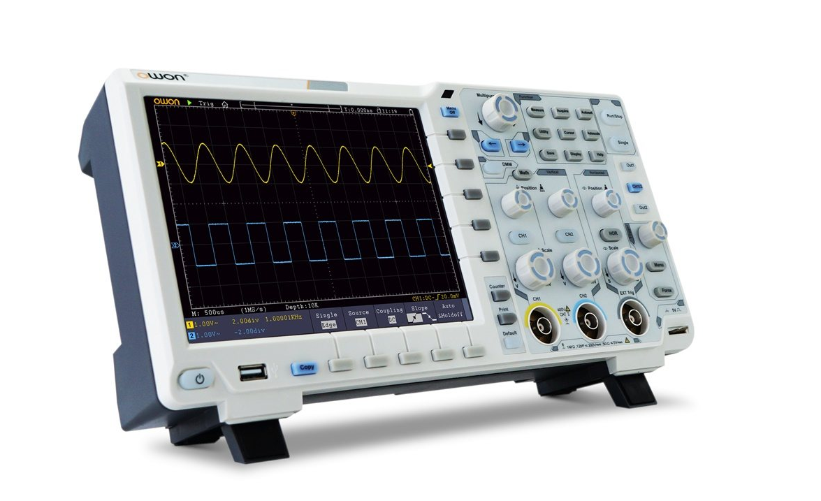
2 channel DSO with 100 MHz bandwidth, 1 GSa/s sample rate, 40 MSa memory depth and VGA interface and 20.3 cm touchdisplay with a resolution of 800 x 600 pixel.
The new XDS n-in-1 digital storage oscilloscop of Owon offers reliably measurement technology for a really good price. The colorful 8″ (20.3 cm) TFT LCD panel with the resolution of 800 × 600 allows an excellent readability of the wave, especially in regards to high data volume or many waves covered reciprocally.
The special features of the XDS series are a multitouch surface (from the XDS3102A) and a high vertical resolution up to 14 bits. The -plus variants are equipped with a 3¾ digit multimeter and a 25 – 50 MHz waveform generator. The XDS series offers a bandwidth of 60 – 300 MHz, a sample rate of 1 – 2 GSa/s in dual channel and a memory depth of 40 MSa per channel.
Delivery including 2 probes, multimeter probes (optional) a USB cable, PC software, a power adapter and a user manual.
Introduction Video
The Owon XDS3102 is for sale for ~500€ (excluding VAT), from various distributors online.
Displaying a custom image or graphic on a LCD display is a very useful task as displays are now a premium way of providing feedback to users on any project. With this functionality, we can build projects that display our own logo, or display images that help users better understand a particular task the project is performing, providing an all-round improved User Experience (UX) for your Arduino or ESP8266 based project. Today’s tutorial will focus on how you can display graphics on most Arduino compatible displays.
The procedure described in this tutorial works with all color displays supported by Adafruit’s GFX library and also works for displays supported by the TFTLCD library from Adafruit with little modification. Some of the displays on which this procedure works include:
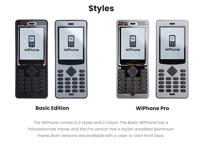
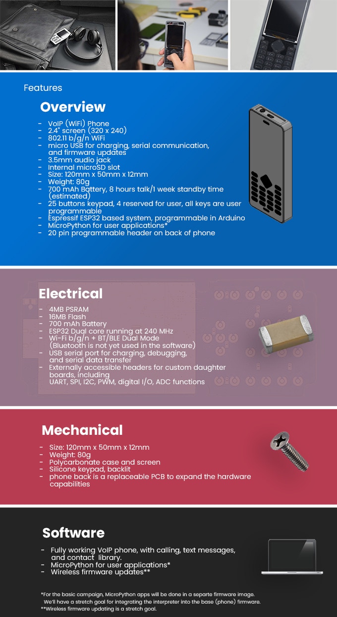
WiPhone is a VoIP mobile phone designed for hackers and makers to be easily modified, repurposed, and adapted.
WiPhone is a unique, minimal phone. It’s designed to enable hackers by making it easy to extend and modify the electronics and software. Something typical phones are not good for. WiPhone is also a VoIP mobile phone. It uses WIFI to make HD voice calls, for free. This means that there is no required service contract – and it’s yours for life.
[…]
WiPhone solves these problems and gives hackers, makers, and engineers the tool we all wish our phones could be. Nice package, direct access to I/O, an easy to program ESP32 processor. All the basics are already set up: user interface, power management and on/off circuit, working code.
The project is live on kickstarter, is already funded and has 7 days to go.
Displaying a custom image or graphic on a LCD display is a very useful task as displays are now a premium way of providing feedback to users on any project. With this functionality, we can build projects that display our own logo, or display images that help users better understand a particular task the project is performing, providing an all-round improved User Experience (UX) for your Arduino or ESP8266 based project. Today’s tutorial will focus on how you can display graphics on most Arduino compatible displays.
The procedure described in this tutorial works with all color displays supported by Adafruit’s GFX library and also works for displays supported by the TFTLCD library from Adafruit with little modification. Some of the displays on which this procedure works include:
While these are the displays we have, and on which this tutorial was tested, we are confident it will work perfectly fine with most of the other Arduino compatible displays.
For each of the displays mentioned above, we have covered in past how to program and connect them to Arduino. You should check those tutorials, as they will give you the necessary background knowledge on how each of these displays works.
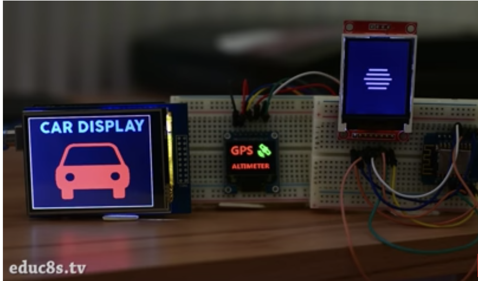
For this tutorial, we will use the 2.8″ ILI9325 TFT Display which offers a resolution of 320 x 340 pixels and we will display a bitmap image of a car.
2.8″ ILI9325 TFT Display
Required Components
To demonstrate how this works with different displays, you can use some of the most popular displays:
As usual, each of the components listed above can be bought from the links attached to them. While having all of the displays listed above may be useful, you can use just one of them for this tutorial.
Schematics
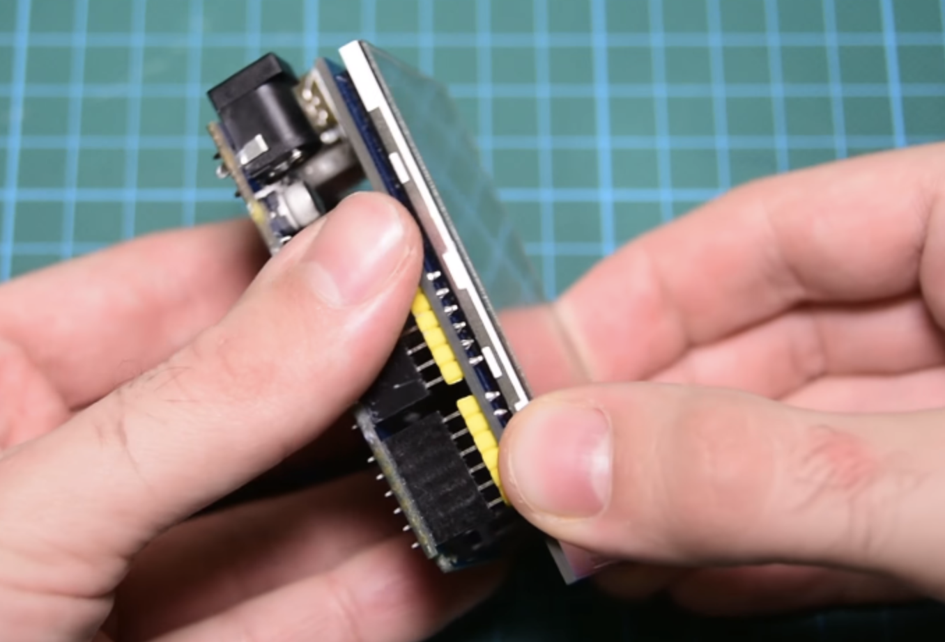
To demonstrate how things work, we will use the 2.8″ TFT Display. The 2.8″ TFT display comes as a shield which plugs directly into the Arduino UNO as shown in the image below.
Connect the Display to the Arduino
Not all Arduino displays are available as shields, so when working with any of them, connect the display as you would when displaying text (we recommend following the detailed tutorial for the display type you use of the above list). This means no special connection is required to display graphics.
With the screen connected, we then proceed to prepare the graphics images to be displayed.
Preparing the Graphics
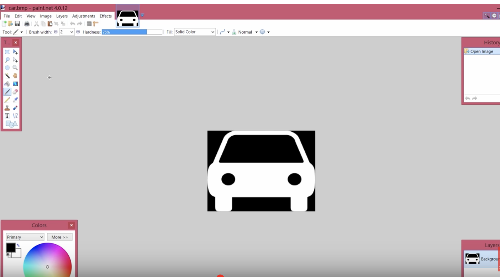
Before an image is displayed on any of the Arduino screens, it needs to be converted to a C compatible hex file and that can only happen when the image is in bitmap form. Thus, our first task is to create a bitmap version of the graphics to be displayed or convert the existing image to a bitmap file. There are several tools that can be used for creation/conversion of bitmap images including, Corel Draw and Paint.net, but for this tutorial, we will use the Paint.net.
Our demo graphics today will be a car. We will create the car on a black background and use a white fill so it’s easy for us to change the color later on.
Using Paint.Net
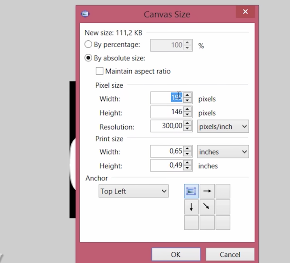
The resolution of the graphics created should be smaller than the resolution of your display to ensure the graphics fit properly on the display. For this example, the resolution of the display is 320 x 340, thus the resolution of the graphics was set to 195 x 146 pixels.
Set the Resolution to Match Your Display
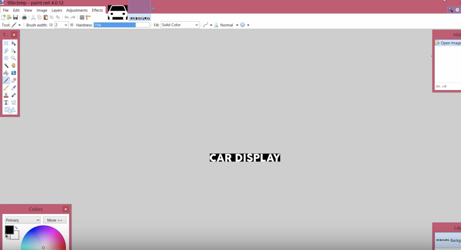
Your graphics could also include some text. Just ensure the background is black and the fill color is white if you plan to change the color within your Arduino code.
Displaying graphical Text
With the graphics done, save both files as .bmp with 24bits color. It is important to keep in mind that large bitmaps use up a lot of memory and may prevent your code from running properly so always keep the bitmaps as small as possible.
The next task is to convert the graphics into byte arrays so they can be used in the code.
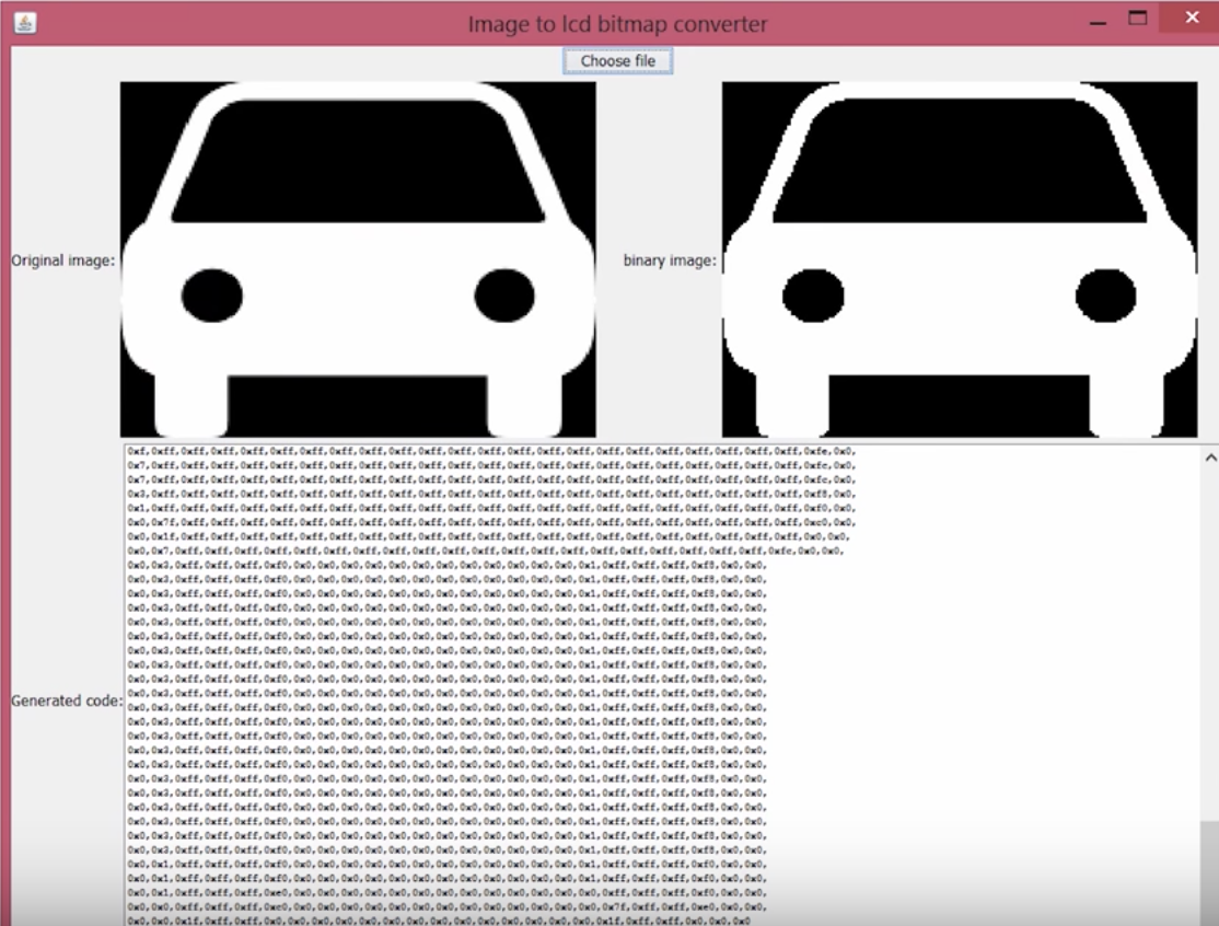
Image2Code is an easy-to-use, small Java utility to convert images into a byte array that can be used as a bitmap on displays that are compatible with the Adafruit-GFX or Adafruit TFTLCD (with little modification) library.
All we have to do is to load the graphics into the software by clicking the “Choose file” button and it will automatically generate a byte array equivalent to the selected bitmap file.
Conversion from Image to Data
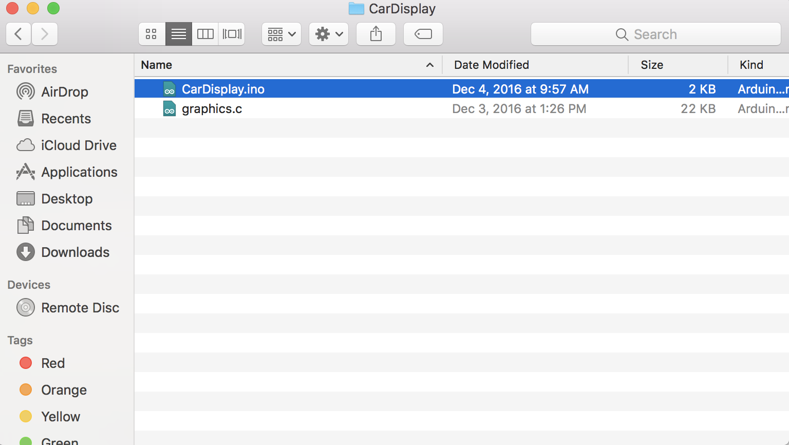
Copy the generated bit array, and create a graphics.c file in the same Arduino project folder where the code will reside.
Ensure the File is in the Same Directory as your main code
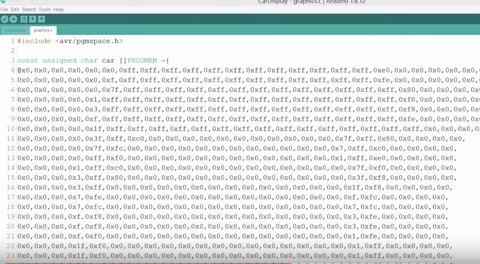
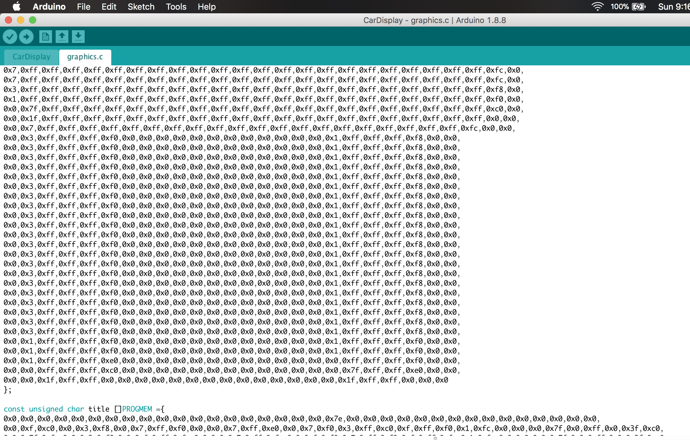
Paste the bit array in the graphics.c file and save. Since we have two graphics (the car and the text), You can paste their data array in the same file. check the graphics.c file attached to the zip file, under the download section to understand how to do this. Don’t forget to declare the data type as “const unsigned char“, add PROGEM in front of it and include the avr/pgmspace.h header file as shown in the image below. This instructs the code to store the graphics data in the program memory of the Arduino.
Copying the Hex file to the Arduino IDE
With this done, we are now ready to write the code. Do note that this procedure is the same for all kind of displays and all kind of graphics. Convert the graphics to a bitmap file and use the Img2code utility to convert it into a hex file which can then be used in your Arduino code.
Code
To reduce the amount of code, and stress involved in displaying the graphics, we will use two wonderful libraries; The GFX library and the TFTLCD library from Adafruit.
The GFX library, among several other useful functions, has a function called drawBitmap(), which enables the display of a monochrome bitmap image on the display. This function allows the upload of monochrome only (single color) graphics, but this can be overcome by changing the color of the bitmap using some code.
The Adafruit libraries do not support all of the displays but there are several modifications of the libraries on the internet for more displays. If you are unable to find a modified version of the library suitable for your the display, all you need do is copy the code of the drawBitmap() function from the GFX library and paste it in the Arduino sketch for your project such that it becomes a user-defined function.
The drawBitmap function takes 6 arguments as shown in the code snippet below;
The first two are the x and y coordinates of a point on the screen where we want the image to be displayed. The next argument is the array in which the bitmap is loaded in our code, in this case, it will be the name of the car and the text array located in the graphics.c file. The next two arguments are the width and height of the bitmap in pixels, in other words, the resolution of the image. The last argument is the color of the bitmap, we can use any color we like. The bitmap data must be located in program memory since Arduino has a limited amount of RAM memory available.
Since using a display without the GFX library is more complex, it’s probably better to do an explanation of how to write the code for this procedure.
As usual, we start writing the sketch by including the libraries required. For this procedure, we will use the TFTLCD library alone, since we are assuming you are using a display that is not supported by the GFX library.
Next, we create the colors to be used, specifying the matching hex values and then create an instance of the TFTLCD library.
#define BLACK   0x0000
#define BLUE    0x001F
#define RED     0xF800
#define GREEN   0x07E0
#define CYAN    0x07FF
#define MAGENTA 0xF81F
#define YELLOW  0xFFE0
#define WHITE   0xFFFF
#define GREY     0xD6BA

Adafruit_TFTLCD tft(LCD_CS, LCD_CD, LCD_WR, LCD_RD, LCD_RESET);
Next, we specify the name of the graphics to be displayed; car and title. At this stage, you should have added the bit array for these two bitmaps in the graphics.c file and the file should be placed in the same folder as the Arduino sketch.
extern uint8_t car[];
extern uint8_t title[];
Next, we write the void setup function. All we do here is to initialize the screen and rotate it to a preferred orientation.
With that done, we proceed to the void loop function, under the loop function, we call the drawbitmap() function to display the car and the text bitmap using different colors.
The last section of the code is the drawBitmap function itself, as earlier mentioned, to use the drawbitmap() function with the Adafruit TFTLCD library, we need to copy the function’s code and paste into the Arduino sketch.
Plug in your screen as shown above. If you are using any other display, connect it as shown in the corresponding linked tutorial. With the schematics in place, connect the Arduino board to your PC and upload the code. Don’t forget the graphics file needs to be in the same folder as the Arduino sketch.
With that done, you should see your screen come up as shown in the image below.
Demo
That’s it for this tutorial guys. The procedure is the same for all kinds of Arduino compatible displays. If you get stuck while trying to replicate this using any other display, feel free to reach out to me via the comment sections below.
Till Next time.
The video version of this tutorial is available on Youtube.
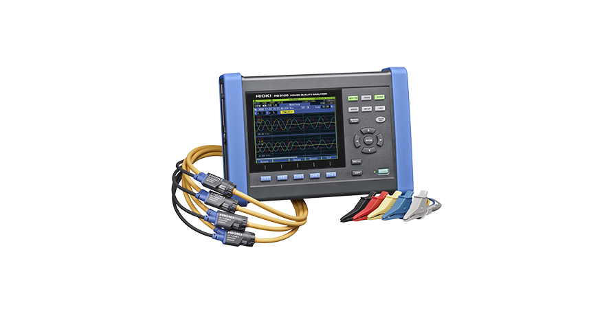
The Hioki PQ3198 portable power analyzer is a best in class power measuring instrument for single to three-phase lines, offering a high degree of precision and accuracy. Verify power problems in accordance with IEC61000-4-30 Class A.
Saelig Company, Inc. has introduced the Hioki PQ3198 Power Quality Analyzer, which can conveniently be used for assessing power usage as well as for investigating power supply problems such as voltage drops, flicker, harmonics, and other electrical issues, so that their causes to be quickly investigated. Hioki portable power analyzers can measure single to three-phase lines with a high degree of precision and accuracy. New features include the ability to drive current sensors straight from the analyzer with enhanced recording capabilities.
The PQ3198 analyzer can be used for single-phase2-wire or 3-wire, three-phase 3-wire or 4-wire plus one extra input channel for voltage, current, power measurement (AC or DC). Sampling at 2MHz, voltages up to 600Vrms (transients to 6kV peak) and currents from 500mA to 5kA can be accommodated, depending on the selected sensor. Comprehensive power analysis of multiple parameters can be made in accordance with the IEC61000-4-30 Class A standard with high accuracy and continuous gapless recording. Voltage dips, swell, inrush, transients to 0.5us, flicker, harmonics, distortion, K factor, etc. can all be analyzed and displayed via the 6.5” TFT LCD. The broadband voltage range allows high-order harmonic component measurements up to 80kHz. In addition to 50/60Hz, the PQ3198 can measure a line 400Hz frequency. An optional battery pack allows continuous isolated use for up to 180 minutes.
The Hioki PQ3198 Power Quality Analyzer simplifies the analysis of power problems: fluctuations in voltage, current, power, harmonics, and flicker when, for instance, connecting a highly variable system such as a renewable energy source or EV charging station to the grid. The data can be further analyzed with the included PQ ONE PC software. The GPS Option PW9005 can be used to synchronize the instrument’s internal time to UTC standard time. This capability eliminates any time difference between multiple instruments.
The Hioki PQ3198 Power Quality Analyzer provides critical robust support for field personnel who need to analyze power characteristics, reliably capturing a full range of power anomalies with an exceptional ease of use. Applications include verifying the power quality of EV rapid chargers, detecting intermittent or poor quality power feeds, assessing light flicker issues, testing for abnormal waveforms when switching to UPS power, solar power quality surveys, etc.
Designed and manufactured by Japan-based Hioki, a world-renowned developer and manufacturer of innovative test and measurement instruments, the PQ3198 Power Quality Analyzer is available now from Saelig Company, Inc. their USA technical distributor.
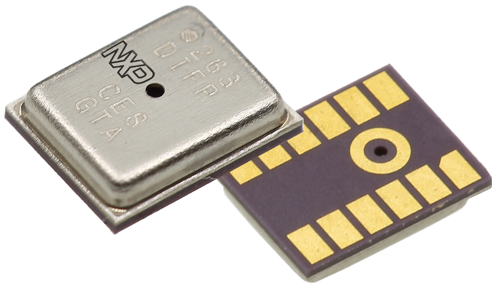
NPS30xx is the last NXP family of digital differential pressure sensor in a tiny 4x5mm LGA package with ceramic lead frame.
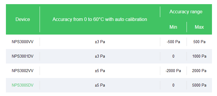
This complete family offers low pressure measurement (NPS3000VV = +/500Kpa, NPS3001DV = 0/1Kpa, NPS3002VV = +/-2Kpa, NPS3005DV = 0/5Kpa) combined with absolute accuracy down to 3Pa. It also offers an ultra-low power consumption down to 3.1uA in a measurement mode.
On top of using the serial SPI or I²C interface, user can also benefit from embedded interrupts to trigger wake up based on various configuration of pressure and/or temperature change – and therefore significantly reduce system power.
This family is targeting 2 different markets :
Heating, Ventilation and Air conditioning market, used as flow sensor when combined with a Venturi element or simple obstruction made by a filter or a fan. The very good offset stability and high accuracy are key parameters here. More specifically, wireless smart filter with a BLE connectivity is a new application that can be targeted thanks the low power capability
Medical market for e-inhaler, drug delivery and CPAP machine. The NPS30xx pressure sensor piezo resistive element is actually protected by a bio-compatible gel coating that will facilitate medical certification. Again interrupt capabilities and low power performance together with very small form factor are the key criteria’s here.