HS101: A high quality, and Cheap DIY Oscilloscope

One of the most interesting thing about being a maker is you never get tool-stranded, with the right components, makers tend to have the ability to build makeshift tools on the go. Today, we will take a look on how to build a cheap version of one of the most important tools for any electronics engineer or maker; The Oscilloscope.

An Oscilloscope – source: sparkfun.com

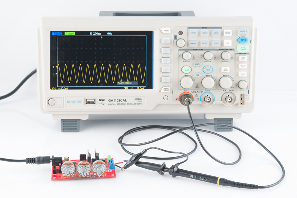
The Oscilloscope is a test instrument used for the visualization and observation of varying signal voltages, usually as a two-dimensional plot with one or more signals plotted against time. They are used in the design and debugging of electronic devices to view and compare waveforms, determine voltage levels, frequency, noise and other parameters of signals applied at its input as it changes with time. This makes Oscilloscopes a very important tool on the desk of an electronics engineer or maker. However, Oscilloscopes are quite expensive, they cost between $45 – $100 for a small oscilloscope and above $300 for advanced oscilloscopes, which puts them beyond the reach of basic users. But what if we could create something cheaper, compact, and highly functional using the components familiar to makers? That is the question that led to today’s tutorial.

HS101 in Action

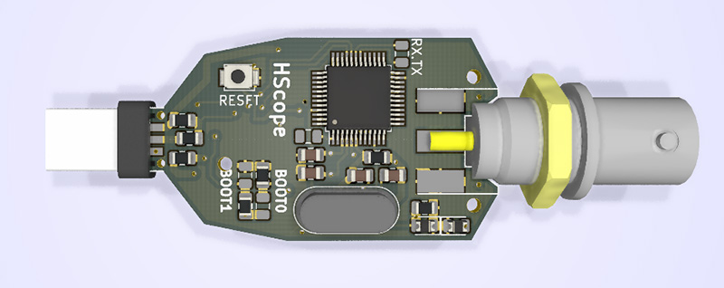
For today’s tutorial, we will build the HS101 Oscilloscope. The HS101 Oscilloscope setup comprises of the HS101 portable and compact DIY oscilloscope, connected to an Android-based mobile phone or tablet running the HScope app.  The oscilloscope is based on the STM32F103 microcontroller which has 2 fast, 12-bits ADC and it samples the signal to be examined (after it has passed  condition elements, like a network of resistors capacitors and diodes) on board.

Some of the features of the HS101 includes;

  • Single Channel Oscilloscope
  • 12 Bits ADC resolution
  • 0-20v Input voltage range
  • Sampling rates between 3KS/s – 1800KS/s
  • Bandwidth 200kHz
  • Up to 100KSa/s continuous acquisition
  • Input noise depends on the sampling rate. < 15mV for sampling rate <=100KSa/s

The oscilloscope can be used in standard situations for tasks like DC measurements while also being useful for long period voltage logging and basic automobile checkups like;

  • Battery level logging
  • Battery Ignition Off Draw (IOD) data logging (with C650-like amp clamp or a DIY tool)
  • Alternator AC ripple level (example here)
  • In-Cylinder Compression Test (with 100 PSIG pressure sensor, example here

Required Components

The following components are required to build this project;

  1. STM32F103C8 Blue Pill
  2. USB to TTL Cable
  3. 1N4007 (2)
  4. 10K Resistor
  5. 2k Resistor
  6. 470pF Capacitor
  7. USB OTG Cable (Micro USB to Micro USB / USB Type-C to Micro USB)
  8. Perforated PCB Boards (anything with 6 to 7 holes should do it).
  9. 6 Pin single row female 2.54mm pin header (2)
  10. Probe and BNC Connector (plain wires or a 3.5mm audio jack can be also be used)

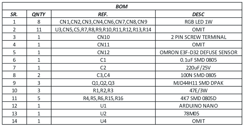
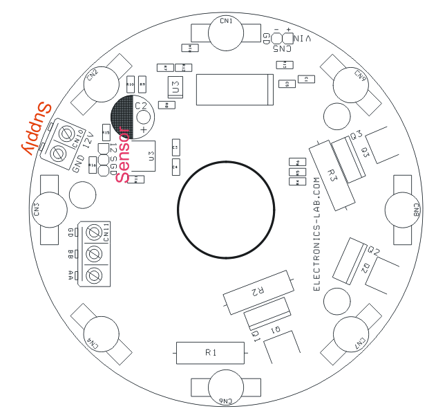
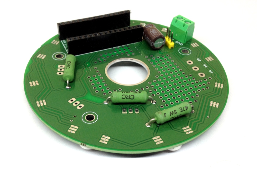
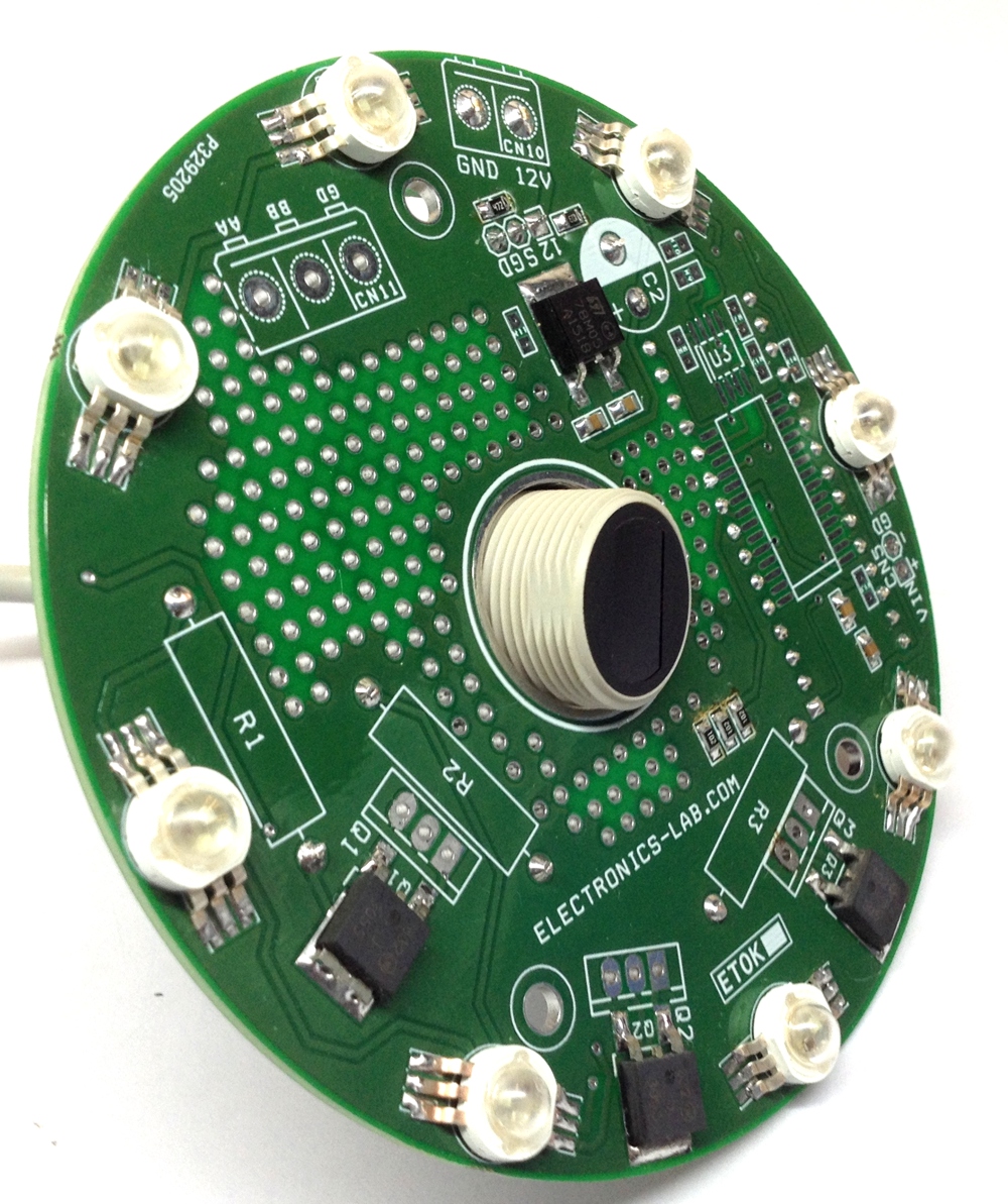
You could also decide to make a Printed circuit board for this project. The BOM, Schematics and the PCB design are attached under the download section of this tutorial.
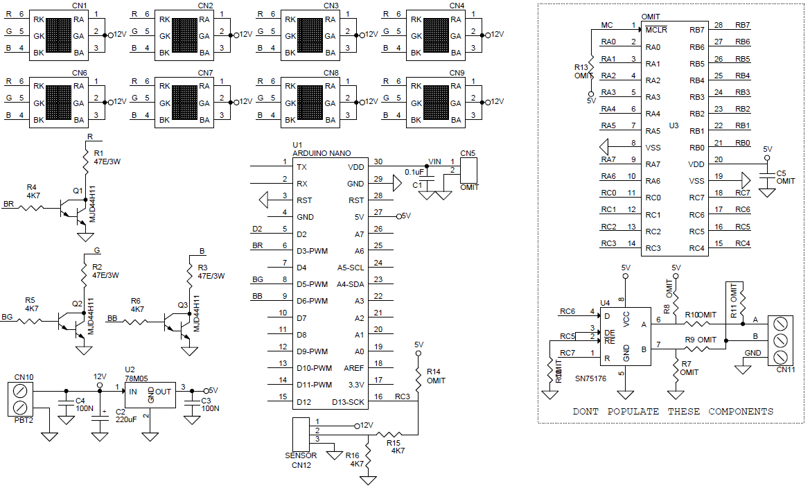
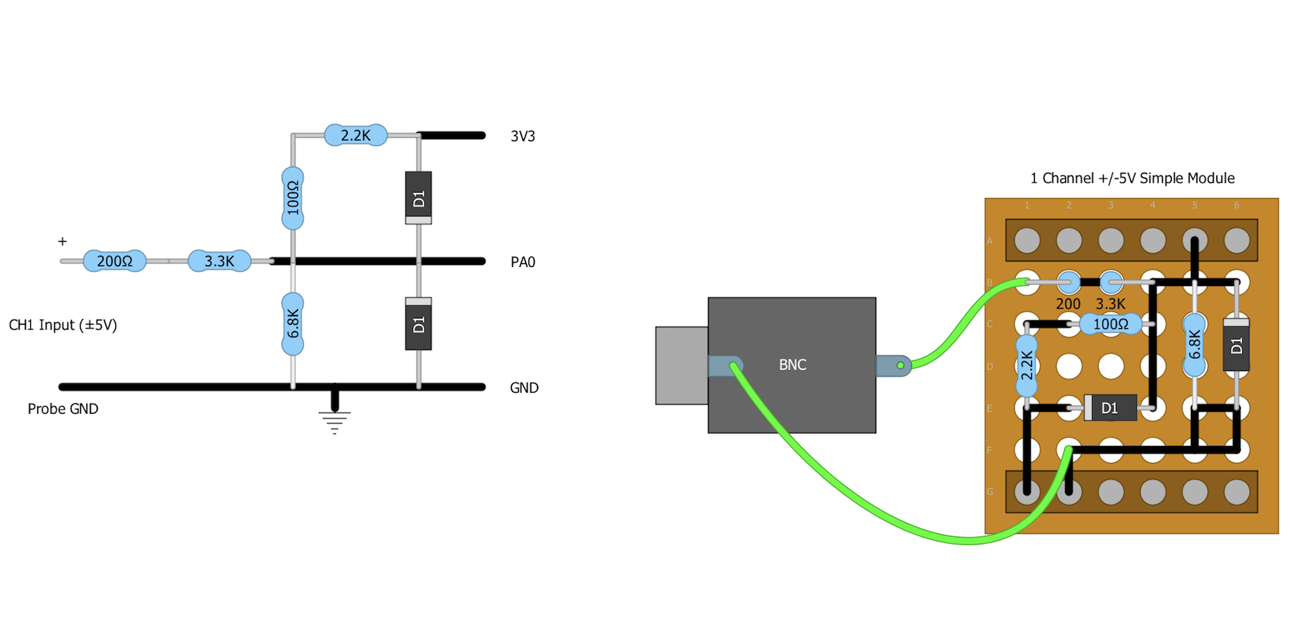
Schematics

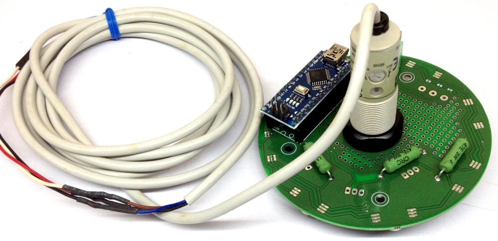
The schematics for this project is unbelievably easy. The Input module comprising of the resistors, capacitors, and diodes is built/soldered on the perforated (proto) board and then mounted on the STM Blue Phil board using the female headers which plug directly into the Blue Phil. This makes the design modular and compact. Connect the components on the protoboard as shown in the schematics below.

Input Module Schematics

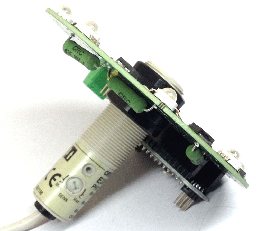
After soldering the parts, plug the input module on the STM Blue pill as shown in the image below.

Plug Input Module on Blue Pill

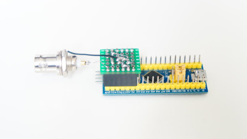
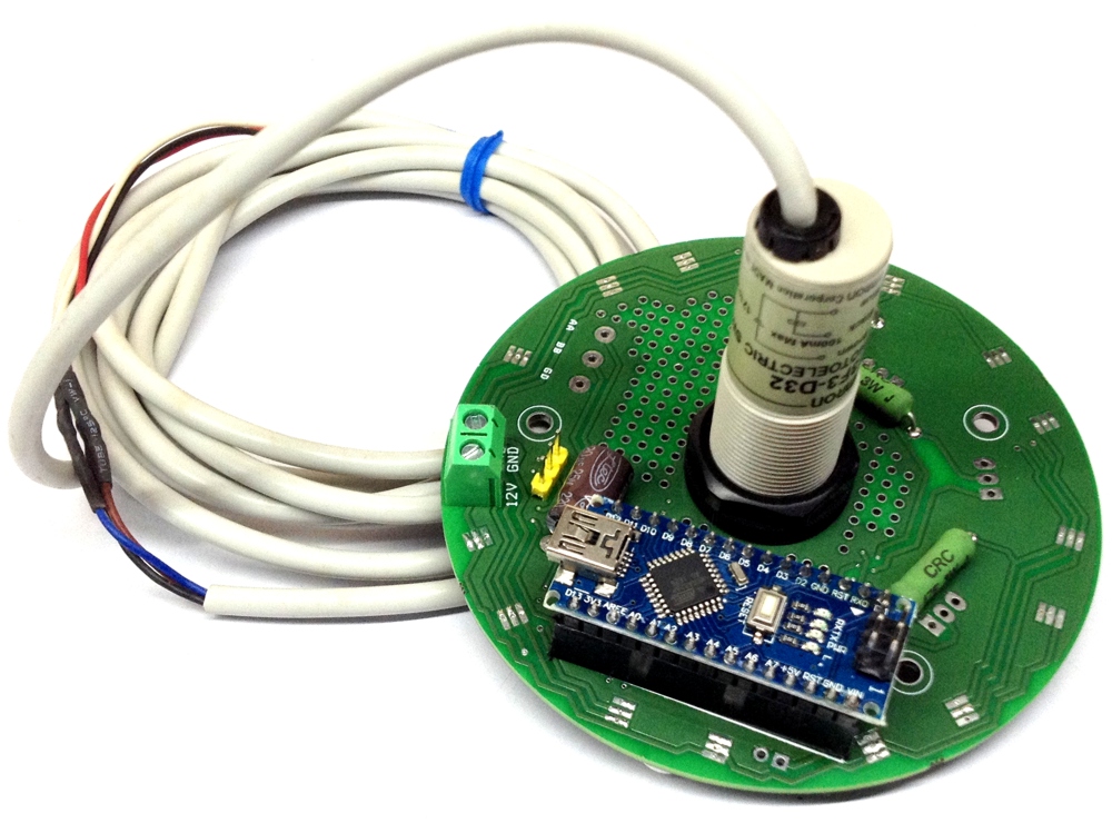
As mentioned above, you could make your own fully customized PCB-based Oscilloscope using the same design for this project. All the files you need including BOM and the PCB are attached under the download section at the end of the tutorial. An image of the PCB version is shown below.

HS101 PCB

Flashing the Firmware

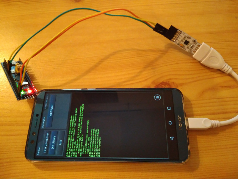
One of the cool things about today’s project is the fact that we will be uploading code to the microcontroller board using a smartphone, which means you don’t need your computer for any part of this project. For today’s tutorial, we will use the STM32 Utils App by Martin Loren. The app comes preloaded with the firmware for the HS101 oscilloscope, so all we need do is to connect the Blue pill microcontroller to your phone via a USB to Serial converter and an OTG cable as shown in the image below.

Flash Firmware Using STM32Utils. (Credit:Time4ee)

The pin map for the connection of the serial to USB cable and the STM32 Blue pill is shown below;

Blue Pill – USB-UART

5V - 5V(or VBus)
PA9 - Rx
PA10 - TX
GND - GND

with the connections done,  press the “Init Chipset” button on the app. You should see the light on the STM come up. Click the “DIY Library” button on the app, select the HS101 Firmware, and click on “Flash Firmware“.

With the firmware upload complete, you can then disconnect the USB to Serial cable and connect the board to the phone via the OTG cable.

That’s it, your oscilloscope is ready!

Demo

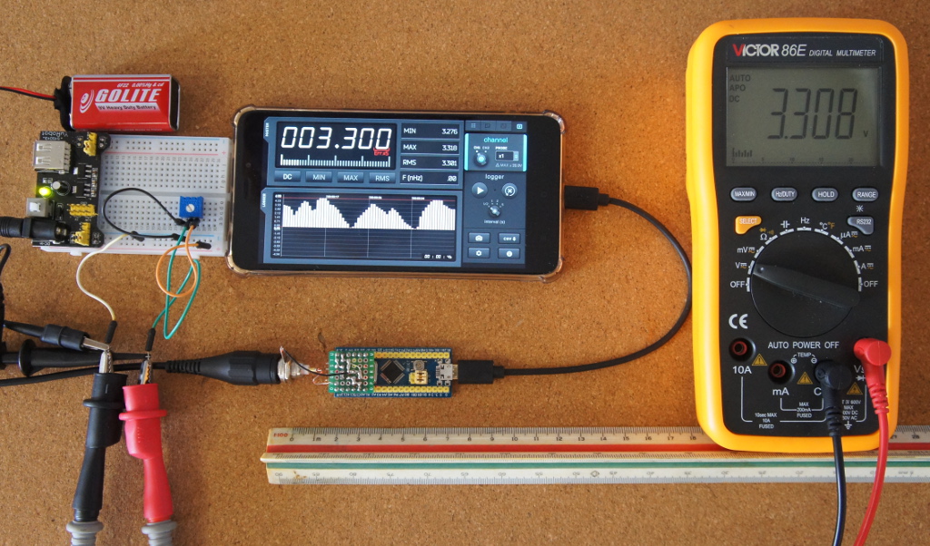
The STM32 is powered by the smartphone via the OTG cable. As soon as it is connected to the phone, the red led of the Blue Pill board should come on. As soon as the STM32 is on, open the HScope app. The app should automatically recognize the oscilloscope and start displaying data.

Connect any signal to the input of the HS101 and you should see the data displayed on the app as shown below.

HS101 Demo

The free-version of HScope app allows using the HS101 as voltage tester and as a simple oscilloscope which might be enough for simple tasks. The full version of the HScope app, on the other hand, provides access to real-time statistics, FFT and could be used to convert the HS101 to a data logger.

Optimizing the Oscilloscope

Noise is the biggest challenge of the HS101 oscilloscope. It is strongly dependent on the phone model and this can be fairly overcome by adding capacitors between GND and 3.3V pins on the Blue Pill board. The value of the capacitor closest to the USB connector can be around 470uF for improvement in data quality.

The Oscilloscope described by this tutorial might not necessarily be capable of replacing the standard Lab Oscilloscope, but this would help you get some of the little tasks done fast, without having to pay huge sums. It is also portable which makes it useful if you move around a lot.

That’s it for today’s tutorial guys. Feel to reach out to me via the comment section if you have any questions or difficulty while replicating the tutorial.

Sources:

Azure Sphere MT3620 Starter Kit for Creating Secured IoT Edge Devices

Avnet Kit
Azure Sphere MT3620 Starter Kit

Last year, Microsoft signed with Avnet as a strategic partner for their Azure platform – a platform for robust cloud computing. This partnership is expected to help boost the already fragile IoT market and adds some level of reputation to it considering Avnet is a big name in the electronics industry and Microsoft a top brand in the software world.

Security is an utmost priority in the growing Internet of Things market. So, to make it end to end secure, a lot of effort have been put to introduce different setups like handshaking, encryption and many more. A breach in security in IoT might not only affect the product in the short run but also impact on the personal brand of the organization.

Highly secured end to end IoT implementations cannot be overemphasized on and with the flood of several IoT development kits, developers might be easy fall prey to unsecured solution setups. Avnet has unveiled the Azure Sphere MT3620 Starter Kit, which supports rapid prototyping of IoT implementations using Microsoft’s Azure Sphere — an end-to-end solution for creating highly-secured, connected microcontroller devices.

Azure Sphere MT3620 Starter Kit

The starter kit launched is built around the Avnet Azure Sphere module which is based on the MT3620 reference development board. The MT3620 is a highly integrated, high-performance IoT MCU with the high level of security necessary for modern, robust internet-connected devices. The MT3620 targets a wide range of IoT applications including smart home, commercial, industrial and many other domains thanks to its extensive I/O peripheral subsystem that allows device design flexibility and freedom.

The starter kit can easily find application in the below markets:

  • Consumer appliances
  • Smart retail.
  • Remote access
  • Building automation software.
  • Factory automation applications.

Specifications:

  • Two MikroEClick Board expansion sockets
  • Built-in Microsoft security.
  • Connectivity: Wi-Fi.
  • Processor: Arm Cortex-A7
  • Grove expansion connector (I2C)
  • Onboard sensors
  • 3-Axis accelerometer
  • 3-Axis Gyro
  • Temperature
  • Pressure/Barometric
  • Interface for optional OLED 128×64 display
  • USB Interface
  • Supports debug, service and recovery UARTs, and JTAG
  • User push switches and LEDs
  • 5V to 3.3V Power regulation
  • DC Supply Input:
  • USB 5V from the host computer
  • Terminal footprints for external 5VDC and VBAT supplies
  • Azure Sphere MT3620 Module features include:
  • MediaTek MT3620AN SoC
  • 3x ISU interfaces pre-configured for UART, SPI, I2C
  • ADC/GPIO: 3x 12-bit ADC inputs (or 3 GPIOs)
  • PWM/GPIO: 9x PWM outputs (or up to 24 GPIOs)
  • RTC (requires VBAT supply)
  • Dual-band 2.4/5GHz 802.11 a/b/g/n WiFi
  • Dual-band 2.4/5GHz chip antenna
  • Production-ready

Azure Sphere MT3620 module is a 33 x 22 mm module and packs a dual-band Wi-Fi chip antenna and a system clock. It provides support of up to 27 configurable GPIOs, including support for UART, I2C, and SPI.

The MT3620 starter kit includes a carrier board that connects the Azure Sphere MT3620 module I/Os to a pair of MikroE sockets, I2C grove connector, OLED graphical display connector, 3D accelerometer & gyro, temperature and light sensors. All of this together, when put in order, the connected device in harmony with each other will give the best of their results. A 5 V power is applied to the board, due to the in-built debugging. Debugging is achieved through USB to UART interface.

The Avnet Azure Sphere MT3620 Starter Kit is now available for purchase for $75 from Avnet. More information can be found on the product and announcement page.

LPS33W – MEMS pressure sensor withstands harsh environment

MEMS pressure sensor: 260-1260 hPa absolute digital output barometer with potted gel package.

STMicroelectronics LPS33W MEMS Pressure Sensor is ultra compact and functions as a digital output barometer. The LPS33W combines a sensing element and an IC interface which communicates through I2C or SPI from the sensing element to the application. Detecting absolute pressure, the sensing element consists of a suspended membrane manufactured using a dedicated process developed by ST.

The LPS33W is available in a ceramic LGA package with metal lid, and is guaranteed to operate over a temperature range extending from -40°C to +85°C. The package is holed to allow external pressure to reach the sensing element, and gel inside the IC protects the electrical components from harsh environmental conditions.

LPS33W Pressure Sensor

Key Features

  • Pressure sensor with potted gel package
  • 260 to 1260hPa absolute pressure range
  • Current consumption down to 3μA
  • High overpressure capability: 20x full scale
  • Embedded temperature compensation
  • 24-bit pressure data output
  • 16-bit temperature data output
  • ODR from 1Hz to 75Hz
  • SPI and I²C interfaces
  • Embedded FIFO
  • Interrupt functions: data-ready, FIFO flags, pressure thresholds
  • Supply voltage: 1.7 to 3.6V
  • ECOPACK® lead-free compliant

The LPS33W operates at just 15µA in high-performance mode, with a 3µA low-power mode and 1µA power-down to help maximize runtime of battery-powered devices. A generous 128-bit FIFO stores up to 40 slots of 32-bit pressure and temperature data, helping save extra power by minimizing intervention from the host microcontroller. A low-pass filter and I2C and SPI digital interfaces are also built-in.

LPS33W Block Diagram

The LPS33W is in mass production now, in a 3.3mm-diameter x 2.9mm cylindrical metal case, priced from $3.60 for orders of 1000 pieces. For more information, visit www.st.com/lps33w-pr

15% Off – Exclusive Farnell Offer

Get 15% discount off Farnell products until the 30th April when buying via OEMsecrets.com

You’ll just need to select the correct code based on your location and apply at checkout with Farnell, when clicking to “Buy Now” through our site. Click the View Offer button below for more information and to claim your discount code.

[VIEW OFFER]

See the most popular codes below. Click Here for a full list of codes and terms.

  • OEMSEU for EU
  • OEMS15UK for United Kingdom
  • OEMS15US for United States
  • OEMS15IN for India

8 RGB LED Driver Shield for Arduino Nano with Optical Defuse Sensor

The board consists of 8 x RGB LEDs 1W, BJT transistors on each LED, series resistor across the LED for current limiting, a hole to mount 18mm optical sensor which may be a defuse sensor for object detection with Arduino nano.  The board can be programed to create multiple RGB LED related applications, like interactive lamp, automatic bathroom light etc. I have used Omron E3F-D32 defuse optical sensor which can detect human or object at a distance up to 300mm. When the sensor detect any object within the range of 300mm its toggles output. The output is PNP type, the range of sensor is adjustable using trimmer pot and also sensor has LED operation indicator. All RGB LED transistors connected to D3, D5, D6 of Arduino PWM pins which helps to create multi-color effects. Optical sensor connected to digital pin D13 of Arduino Nano. Board also has prototype area to mount other sensors or circuitry and some additional components are provided to make PIC based applications or RS485 based RGB LED controller. Circuit works with 12V DC input.

8 RGB LED Driver Shield for Arduino Nano with Optical Defuse Sensor – [Link]

8 RGB LED Driver Shield for Arduino Nano with Optical Defuse Sensor


The board consists of 8 x RGB LEDs 1W, BJT transistors on each LED, series resistor across the LED for current limiting, a hole to mount 18mm optical sensor which may be a defuse sensor for object detection with Arduino nano.  The board can be programed to create multiple RGB LED related applications, like interactive lamp, automatic bathroom light etc. I have used Omron E3F-D32 defuse optical sensor which can detect human or object at a distance up to 300mm. When the sensor detect any object within the range of 300mm its toggles output. The output is PNP type, the range of sensor is adjustable using trimmer pot and also sensor has LED operation indicator. All RGB LED transistors connected to D3, D5, D6 of Arduino PWM pins which helps to create multi-color effects. Optical sensor connected to digital pin D13 of Arduino Nano. Board also has prototype area to mount other sensors or circuitry and some additional components are provided to make PIC based applications or RS485 based RGB LED controller. Circuit works with 12V DC input.

Features

  • Supply 12V DC
  • 8 RGB LEDs Each 1W
  • Defuse Reflective Sensor for Interactive Light
  • PCB Diameter 92.06 MM

Schematic

Parts List

Connections

Photos

OMRON E3F3 Photoelectric Sensor Datasheet

Video

6A/6V Buck Converter with 16V Input Operates at up to 2MHz

16V, 6A, High Efficiency, Synchronous, Step-Down Converter with Adjustable Current Limit.

Monolithic Power Systems (MPS) introduced the MPQ8626, a fully integrated, high-frequency, synchronous, buck converter. According to MPS, the MPQ8626 offers a very compact solution that achieves up to 6A of output current with excellent load and line regulation over a wide input supply range. The MPQ8626 operates at high efficiency over a wide output current load range.

Typical applications for the buck converter include telecom and networking systems, server, cloud-computing, storage, base stations, general purpose point-of-load (PoL), 12V distribution power systems, high-end TV, game consoles, and graphic Cards.

An internally compensated constant-on-time (COT) control that provides fast transient response and eases loop stabilization.

With MODE configuration, the operating frequency can be set to 600kHz, 1100kHz, or 2000kHz easily, allowing the MPQ8626 frequency to remain constant regardless of the input and output voltages.

The device has an internal 1.5ms timer that controls the output voltage start-up ramp. This internal timer can be increased by adding a capacitor on TRK/REF. An open-drain power good (PGOOD) signal indicates if the output is within its nominal voltage range. PGOOD is clamped at about 0.7V with an external pull-up voltage when the input supply fails to power the MPQ8626.

Full protection features include over-current protection (OCP), over-voltage protection (OVP), under-voltage protection (UVP), and over-temperature protection (OTP).

Features of MPQ8626

  • Wide Input Voltage Range
  • 2.85V to 16V with External 3.3V Vcc Bias
  • 4V to 16V with Internal Vcc Bias or External 3.3V Vcc Bias
  • 6A Output Current
  • Programmable Accurate Current Limit Level
  • Low RDS(ON) Integrated Power MOSFETs
  • Proprietary Switching Loss Reduction Technique
  • Adaptive Constant-On-Time (COT) for Ultrafast Transient Response
  • Stable with Zero ESR Output Capacitor
  • 0.5% Reference Voltage Over 0°C to +70°C Junction Temperature Range
  • 1% Reference Voltage Over -40°C to +125°C Junction Temperature Range
  • Selectable Forced CCM or Pulse-Skip Operation
  • Excellent Load Regulation
  • Output Voltage Tracking
  • Output Voltage Discharge
  • PGOOD Active Clamped at Low Level during Power Failure
  • Programmable Soft-Start Time from 1ms and Up
  • Pre-Bias Start-Up
  • Selectable Switching Frequency from 600kHz, 1100kHz, and 2000kHz
  • Non-Latch for OCP, OVP, UVP, OTP, and UVLO
  • Output Adjustable from 0.6V to 0.9 x Vin Up to 6V Max
  • Available in a QFN-14 (2mmx3mm) Package

The buck converter has 2.85V to 16V input voltage with external 3.3V Vcc bias or an input voltage range of 4V to 16V with internal Vcc bias or external 3.3V Vcc bias. The device features 6A output current. The output is adjustable from 0.6V to 0.9 x Vin up to 6V max.

MPQ8626 has selectable forced CCM or pulse-skip operation, and it offers output voltage tracking and output voltage discharge. The converter employs the company’s proprietary switching loss reduction technique.

The MPQ8626 requires a minimal number of readily available, standard, external components and is available in a QFN-14 (2mm x 3mm) package.

PicoScope 4 Channel 5GHz Sampler-Extended Real Time Oscilloscope

The PicoScope 9404-05 oscilloscope brings very high speed performance at less than half the cost of traditional benchtop solutions.

Saelig Company, Inc. has introduced the PicoScope 9404-05 5GHz oscilloscope – a unique PC-based high-resolution device which brings affordable high-speed performance by combining the benefits of real-time and equivalent-time sampling with very high analog bandwidth. The PicoScope 9404-05 has four 5GHz 50 ohm input channels, each with its own advanced 12-bit ADC, which provide the required timing and display resolution for accurately measuring and visualizing high-speed repetitive analog and data signals. This tool can capture pulse and step transitions to 70ps, impulses down to 140ps, and clocks and data eyes to 3Gb/s.

The PicoScope 9404-05 has a built-in full-bandwidth trigger for each channel, with pre-trigger ETS (equivalent-time sampling) capture available to well above the Nyquist sampling rate. The PicoSample 4 software is provided at no extra charge and is derived from previous Pico products.  It benefits from more than ten years of development and optimization.  As they become available, new software features and updates are provided at no additional cost.

PicoScope 9404, front and back view

The high-resolution software display can be resized to fit any window, filling 4k and even larger for multiple monitors. Four independent zoom channels can show different views of captured data to a resolution of 1ps. Most of the controls and status panels can be shown or hidden according to various needs, allowing optimal use of the display area.

Most high-bandwidth measurement applications tend to involve repetitive signals or clock-related data streams.  These are ideal for analysis by equivalent-time sampling systems. The 9404-05 Sampler-Extended Real Time Oscilloscope (SXRTO), with acquisitions running at up to 2 million triggered captures per second, enables very fast signals to build up in the display quickly.

The 9404-05 is compact enough to place on a workbench in close proximity to a device under test.  Apart from the controlling PC, everything needed is built into the oscilloscope, with no expensive hardware or software add-ons required.

Features

  • 5GHz bandwidth, 70ps transition time
  • 1TS/s (1ps) equivalent-time sampling
  • Four channels with 12-bit 500MSa/s ADCs
  • Pulse, eye and mask testing to 70ps and 3Gb/s
  • Up to 2 million triggered captures per second
  • Logical, configurable, touch-compatible Windows user interface
  • Comprehensive built-in measurements, zooms, data masks and histograms

Made by Pico Technology, Europe’s award-winning test and measurement manufacturer, the PicoScope 9404-05 5GHz oscilloscope is available now at $14,995.00 from Saelig Company, Inc. their USA technical distributor.

Teeny-Tiny Bluetooth Transmitter Runs on Less Than 1 mW

Bluetooth Low Energy data packets can now be sent by millimeter-size IoT motes. By Samuel K. Moore @ spectrum.ieee.org

Engineers at the University of Michigan have now built the first millimeter-scale stand-alone device that speaks BLE. Consuming just 0.6 milliwatts during transmission, it would broadcast for 11 years using a typical 5.8-millimeter coin battery. Such a millimeter-scale BLE radio would allow these ant-size sensors to communicate with ordinary equipment, even a smartphone.

The transmitter chip, which debuted last month at IEEE International Solid-State Circuits Conference, had to solve two problems, explains David Wentzloff, the Michigan associate professor who led the research. The first is power consumption, and the second is the size of the antenna. “The size of the antenna is typically physics-based, and you can’t cheat physics,” says Wentzloff. The group’s solution touched on both problems.

An ordinary transmitter circuit requires a tunable RF oscillator to generate the frequency, a power amplifier to boost its amplitude, and an antenna to radiate the signal. The Michigan team combined the oscillator and the antenna in a way that made the amplifier unnecessary. They called their invention a power oscillator.

read more

Ugoos AM6 Fan-Cooled S922X TV Box is launching Soon

The popular UGOOS brand has announced the launch of a TV Box powered by Amlogic S922X SoC called UGOOS AM6. Ugoos AM6, in contrast with older model, will include a fan for active cooling, providing optimal performance for the new Amlogic processor. While there are no available photos of the enclosure so far, Ugoos share some pictures of the board and specifications. UGOOS AM6 will run Android 9.0 just like Beelink GT-K, and other TV Boxes that will use the S922X SoC. AM6 TV Box will be available in the default version with 2GB of RAM and 16GB eMMC.

Ugoos AM6 specifications:

  • SoC – Amlogic S922X hexa-core big.LITTLE processor with 4x Arm Cortex A73 cores, 2x Arm Cortex A53 cores, Arm Mali-G52 MP6 GPU; 12nm manufacturing process
  • System Memory – 2GB LPDDR4 RAM (3GB/4GB optional)
  • Storage – 16GB eMMC flash (8GB/32GB optional), micro SD card slot
  • Video Output
    • HDMI 2.1 up to 4K @ 75 Hz with CEC, HDCP 2.2, HDR support
    • 3.5mm AV port for composite video (and stereo audio)
  • Video – 4K UHD H.265/VP9/AVS2 video decoding up to 60 fps
  • Audio – Digital audio via HDMI, analog stereo audio via AV port, S/PDIF port
  • Connectivity – Gigabit Ethernet, dual band 802.11 b/g/n/ac WiFi 5 MIMO RSDB, Bluetooth 5.0 via Ampak AP6398S module
  • USB – 1x USB 3.0 OTG/Host port, 3x USB 2.0 ports
  • Misc – IR receiver, IR output port, battery header (for RTC?), LED header, 12-pin I/O header, Wake on LAN function
  • Power Supply – 12V/2A via DC power barrel jack
  • Dimensions – TBC
UGOOS AM6

Other significant differences against Beelink GT1-K are that Ugoos AM6 should cost less since the default option has less memory (2GB) and storage (16GB). WiFi performance is expected to be good thanks to AP6398S module with MIMO and RSDB (Real Simultaneous Dual Band ) support.

The company did not provide any pricing or launch date.

Source: CNXSoft

TOP PCB Companies