New Grove AI HAT for Edge Computing is released from SeedStudio
Seeed Studio announced a Grove HAT for Raspberry Pi based on the Sipeed RISC-V MAix. This follows after Sipeed launched their 64-bit RISC-V MAix module, crowdfunding a series of boards on Indiegogo at the end of last year. The MAix module is based on Kendryte’s K210 processor, which features two 64-bit RISC-V CPU cores, each core with a built-in independent FPU, and 8Mb of SRAM. It is further equipped with an onboard neural network processor (KPU) for enhancing machine vision applications at up to 60fps for QVGA and 30fps for VGA. Also, there is an audio processor (APU) which supports up to 8 microphones at sampling rates up to 192KHz, with Fast Fourier Transform (FFT) hardware acceleration.
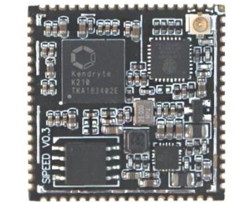
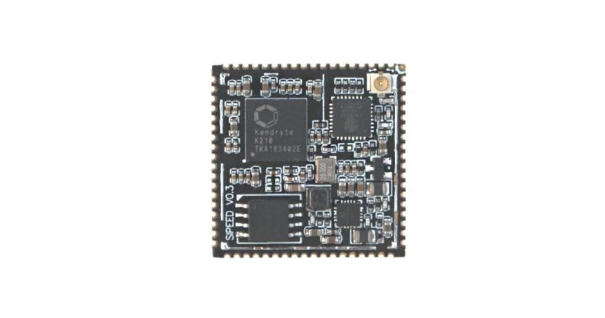
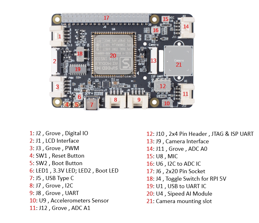
Core Module: Sipeed MAIX-1 without WiFi
The Grove HAT has two versions that will be released. One is based on the Sipeed MAix-I with Wi-Fi, and the other version is without networking. Both boards can be utilized as a Raspberry Pi HAT, or function autonomously. The HAT is designed to offer an onboard 12-bit ADC, a display interface, a camera interface, and six Grove connectors—2×digital, 1×I2C, 1×UART, and 2×analog. Power option for the HAT will be through a USB-C connector. The HAT will utilize the Espressif ESP8285 to provide Wi-Fi support for the wireless version of the HAT.
Seeed Studio is coming up with “the basic layout” for the upcoming HAT but wants to ask the community what features they would like to see before production will progress. Seeed Studio says
Check out the basic layout we have so far and let us know what features you would like to see and have the chance of making it to the final product. If your idea makes it to mass production, we will send you a free sample with your name customized onto the board! These products are designed for you and the rest of the community, so it only makes sense for us to listen to what you want for your next AI project.
If you have any bright idea about what should be featured on the board, you should get in touch with Seeed Studio, and if they like your idea, you might get yourself a free board with your name customized on it.
Visit Seeed Studio product page to get more information on the Sipeed MAix-IHAT.
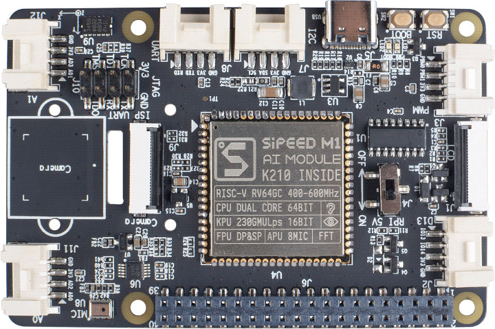
Update 06/05/2019 – Seeedstudio has revealed specifications and photos of the board and it’s now on pre-order.
Grove AI HAT specifications:
AI Module – Sipeed “MAIX” M1 with Kendryte K210 dual core RISC-V processor @ 600 MHz, KPU Convolutional Neural Network (CNN) hardware accelerator, APU audio hardware accelerator, 8 MB general purpose SRAM including 5.9MB usable as AI SRAM memory
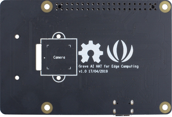
Camera I/F – DVP camera support; two mounting locations (top and bottom of the board)
Display I/F – Supports for Sipeed 2.4″ QVGA LCD display
Audio – Built-in microphone
USB – 1x USB 2.0 Device type C for power and programming
Expansion
40-pin Raspberry Pi connector with I2C/UART/SPI/I2S/PWM/GPIO.
6x Grove connectors: 2x analog, 1x UART, 1x I2C, 1x PWM, 1x digital
Debugging – 8-pin UART/JTAG header
Misc – Boot & reset buttons, boot (user programmable) & power LEDs, switch for RPi 5V, on-board 3-axis accelerometer
Power Supply – 5V via USB type-C port, or Vin pin on Raspberry Pi header
Dimensions – 83 x 55 mm (4x Raspberry Pi HAT mounting holes)
Pre-order price is $24.50 after which it will be $28.50, and shipping is scheduled for mid-June. Seeed Studio is also planning to release a kit with the camera and an LCD as found in the company’s Sipeed MAIX BiT kit.
(UPDATE 20/05/2019) more information and tutorials can be found on wiki.seeedstudio.com
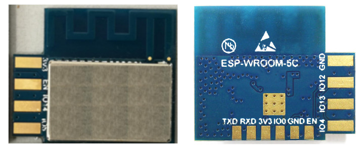
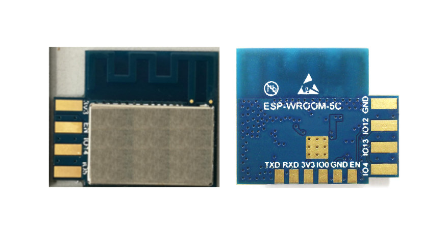
Seems we don’t have enough ESP8266 or ESP8285 WiFi modules in the market, and based on an FCC listing, we now know that Espressif Systems has been working on another ESP8285 WiFi module – ESP-WROOM-5C – designed to be side-mounted on a PCB.
ESP-WROOM-5C specifications:
SoC – Espressif Systems ESP8285
Wi-Fi802.11 b/g/n WiFi 4 @ 2412 MHz ~2462 MHz;
Station/SoftAP/SoftAP + Station modes
WPA/WPA2 security with EP/TKIP/AES encryption
PCB antenna
Peripheral interfaceI2C/IR Remote Control
GPIO/PWM
Operating voltage – 2.7V ~ 3.6V
Operating current – Average: 80 mA
Minimum current delivered by power supply – 500 mA
Dimensions – 19 x 16 x 3.2 mm
Temperature Range – -40°C ~ 105°C
Reliability Tests – HTOL/HTSL/uHAST/TCT/ESD
The module supports firmware upgrade over UART or OTA (Over-The-Air). Software development can be done with the IDF SDK for custom firmware, but “Cloud Server development” is also possible, and an Android/iOS app can be provided for user configuration.
There isn’t more information about ESP-WROOM-5C publicly available and you can find the user manual (PDF) for more technical details.
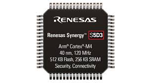
Design your next IoT solution using the Synergy S5D3 MCU
The S5D3 adds a new tier to the S5 MCU group for applications that require a high-performance Cortex M4F core at a very attractive price point, that does not require on-chip graphic acceleration or Ethernet connectivity. The S5D3 is built on a highly efficient 40nm process, and fully supported by the Synergy™ Software Package (SSP). From a solution approach S5D3 offers a nice suitable specification which fits different IoT application requirements like Security, large embedded RAM and power consumption.
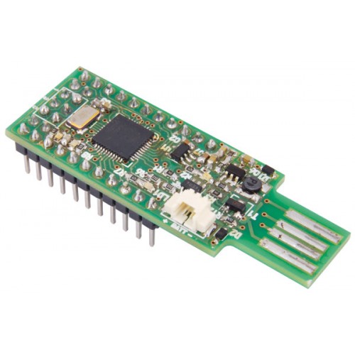
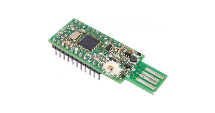
Miniduino is a small (19x40x3,5 mm, pin-strip and USB connector excluded) Arduino board with minimal hardware, but with access to all I/O like the Nano board and equipped with a USB connector with direct insertion integrated into the PCB: practically an Arduino Pen Drive.
The board is based on the Atmel ATmega32U4 microcontroller, which is the same one used on the Arduino Leonardo, Micro and other boards; not for nothing, thanks also to the bootloader written by means of the ICSP connection, once inserted in the USB socket of a Personal Computer it is recognized as Arduino Leonardo.
The ATMega32U4 has the USB device, so it is possible to load the sketch without having to use a USB/TTL converter. It can also simulate a keyboard or mouse, which is useful on many occasions.
In addition, the typical Arduino LEDs are available, ie those that show the serial activity (LD1 and LD3) and the LED for general applications (LD2).
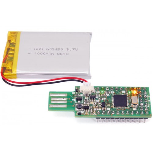
The board is designed to be powered via USB or through a nominal 3.7V lithium battery (to be connected to the +/- BAT contacts). The battery is charged when the card is inserted into the USB socket of the PC (or connected to it via a USB-A / USB-A extension cable) or in a charger with USB output. The current supplied for the battery charge is about 100 mA.
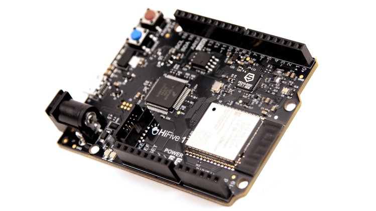
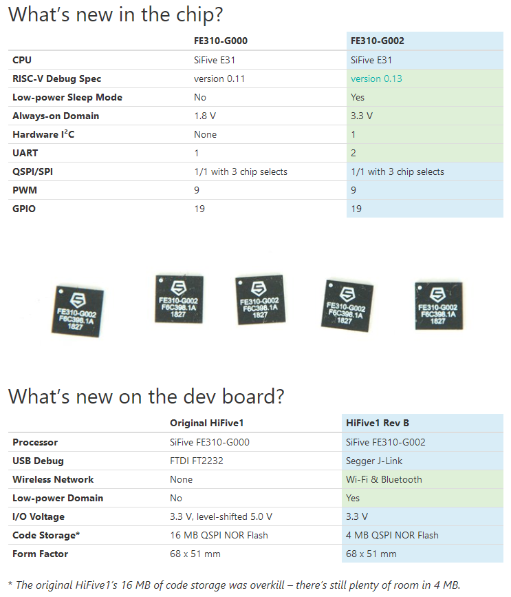
HiFive1 Rev B – The Second Generation HiFive1 Dev Board and the Freedom Everywhere SoC, FE310
SiFive launched an upgraded Freedom Everywhere SoC and corresponding development kit, the HiFive1 Rev B, powered by SiFive’s E31 CPU, the FE310-G002. A small yet mighty 68 mm x 51 mm, the HiFive1 Rev B can connect to Arduino-compatible accessories and is a great platform for real-time embedded applications.
Since the launch of the original HiFive1 and the FE310 in 2016, we have received lots of great community feedback. The FE310-G002 is an upgrade to the Freedom Everywhere SoC, that adds support for the latest RISC-V Debug Spec 0.13, hardware I²C, two UARTs, and power gating the core rail in low power sleep modes. Like the original FE310, the FE310-G002 features SiFive’s E31 CPU core complex, a high-performance, 32-bit RV32IMAC core with a 16 KB L1 instruction cache, a 16 KB data SRAM scratchpad, and hardware multiply/divide. Running at 320+ MHz, the FE310 is among the fastest microcontrollers on the market.
The HiFive1 dev board has also been upgraded. Powered by the FE310-G002, the new HiFive1 Rev B has wireless connectivity through an onboard Wi-Fi/Bluetooth module. The USB debugger has been upgraded to Segger J-Link, with support for drag & drop code download. In favor of driving GPIO directly from the FE310, the HiFive1 Rev B supports 3.3 V I/O only.
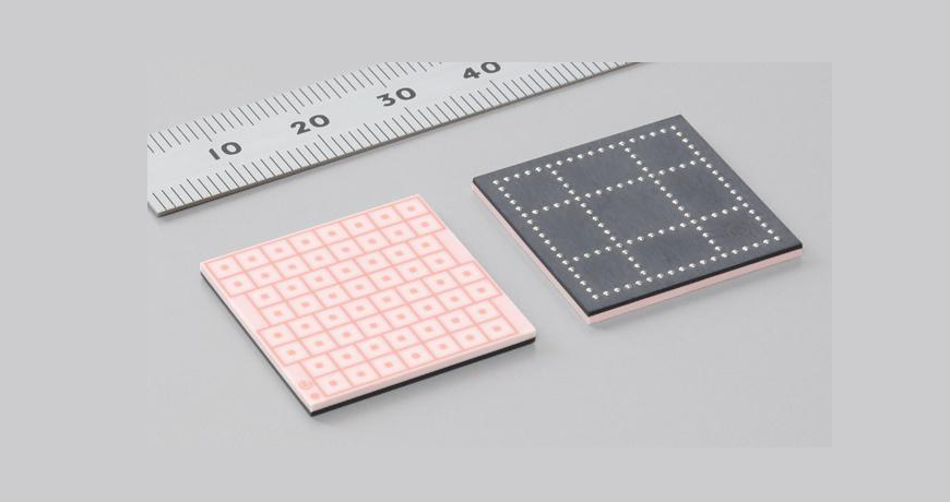
Murata has released a high gain antenna module that facilitates communication up to 4.62 Gbps. The new millimeter-wave RF antenna module will contribute to the creation of next generation wireless networks that utilise the 60 GHz frequency by supporting the IEEE802.11ad millimeter-wave wireless LAN standard.
The need is growing for faster internet communications in line with the increase in bandwidth required by internet contents such as ultra-high definition (HD, 4K) video, augmented reality (AR), and virtual reality (VR). In addition, constructing wired networks that cover wide areas requires enormous amounts of cables and labour, and the costs of constructing and maintaining this infrastructure are also considerable.
Dubbed LBKA0ZZ1NH-317, the new module is anticipated to be utilised in a wide range of applications such as for communication between mobile phone base stations including next-generation 5G wireless communication, for communication between Wi-Fi hotspots, and for use in wireless communication networks in smart cities.
Murata’s RF module realises optimised antenna beamforming using a proprietary low temperature co-fired ceramics (LTCC) circuit board capable of facilitating high-precision 60 GHz band communication. In addition to communication via a standalone module, by combining multiple modules it is possible to extend the communication range and link outdoor base stations several hundred meters apart for multi-gigabit communication. The LTCC circuit board’s high heat resistance and low moisture absorption ensure excellent operational reliability and enable use even in outdoor base station environments.
The highly efficient antenna module operation realises low transmission line loss between the IC and the antenna thanks to the low-loss material characteristics of the LTCC. The modularised RFIC and antenna package eliminates the need to design new millimeter-wave RF circuitry, which reduces the amount of labour required for developing new network equipment.
The module exhibits a high gain of 37.5 dBm typical EIRP with CW signal and saturated power. The RFIC in the module is able to support multi-tile RF module operation. It helps users get higher output power, better Rx sensitivity and longer communication distance.
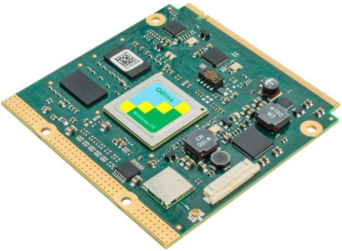
F&S Elektronik Systeme has announced specs for its “efus MX8X” module, which runs Linux on a dual- or quad-core -A35 i.MX8X SoC, and offers up to 2GB RAM and 64GB eMMC plus dual GbE, WiFi/BT, 4K video, and optional industrial temp support. The 2 x 47 x 11mm, 15-gram efus MX8X module is designed based on NXP’s low-powered i.MX8X. A host of efus-branded modules exploits the power-sipping NXP SoCs, like the i.MX6 UltraLite in the efus A7UL.
The module will support industrial automation and control, HMI, robotics, building control, display/audio, infotainment, and telematics applications. The efus MX8X will feature dual-core DualX or quad-core QuadXPlus models, which features 1.2GHz Cortex-A35 cores, multi-format VPU with 4K decode, Tensilica HiFi 4 DSP, and a 266MHz Cortex-M4F MCU which is supported with FreeRTOS. The efus MX8X seems to be the first board based on the i.MX8X by the company, which can be found in several new computer-on-modules, like Kontron’s Qseven-Q7AMX8X.
The efus MX8X is equipped with up to 2GB RAM, up to 512MB SLC NAND flash, and up to 64GB eMMC storage. The module is fitted with 802.11ac, Bluetooth 5.0 BLE (and 2.1 + EDR), and an antenna socket. Available also are dual GbE controllers. The module will ship with a Yocto/BuildrootLinux stack with U-Boot. The image provided shows a Windows CE tag, but we are yet to see the aging Windows CE listed as an i.MX8X option. The announcement says that the module will ship with the DualXPlus, but the product page says it will ship with the DualX. The DualXPlus has a 4-shader, unlike the DualX’s 2-shader Vivante GPU. The efus MX8X enables single USB 3.0, 2.0 ports plus 2x CAN, 4x UART, 4x I2C, and 2x SPI.
A matrix keyboard is also mentioned, as well as PWM, SDIO, and PCIe interfaces. Media I/O option is a 230-pin MXM2 connector which includes MIPI-DSI and 24-bit LVDS along with analog resistive and PCAP touch support via I2C. The module is further equipped with MIPI-CSI and I2S audio. The product page says the 5V module will be available in 0 to 70°C, -20 to 70°C, and -40 to 85°C models, while the announcement says 0 to 70°C and -20 to 85°C. The module runs at 4W, with long-term availability support extending through 2028. F&S plans to ship the efus MX8X in Q3 2019 at an undisclosed price.
F&S Elektronik Systeme plans to ship the efus MX8X in Q3 2019 at an undisclosed price. More information can be found on the announcement and product page.
KBox A-230-LS with SMARC-sAL28 offers up to five TSN-enabled 1GB Ethernet ports for IoT applications
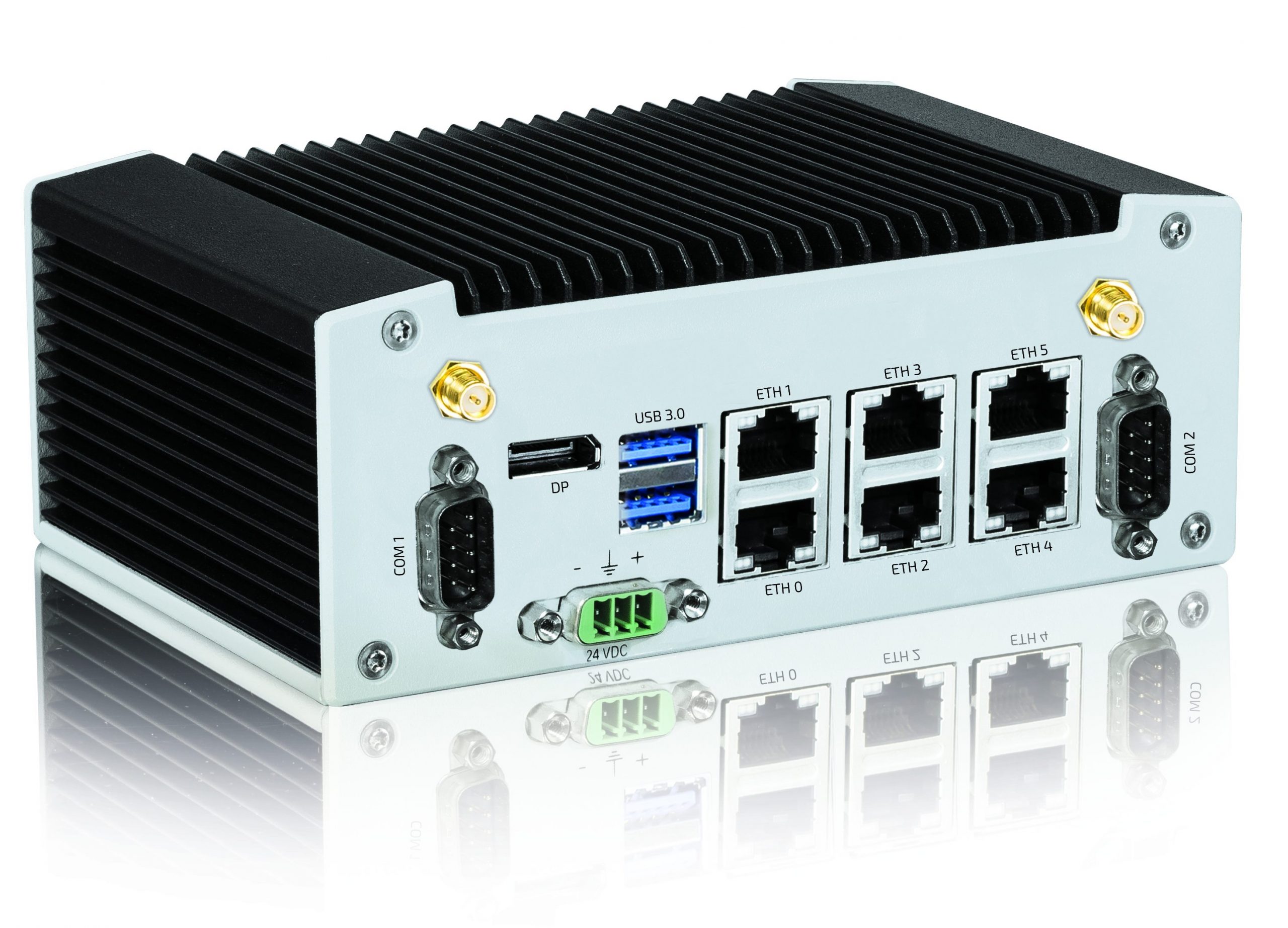
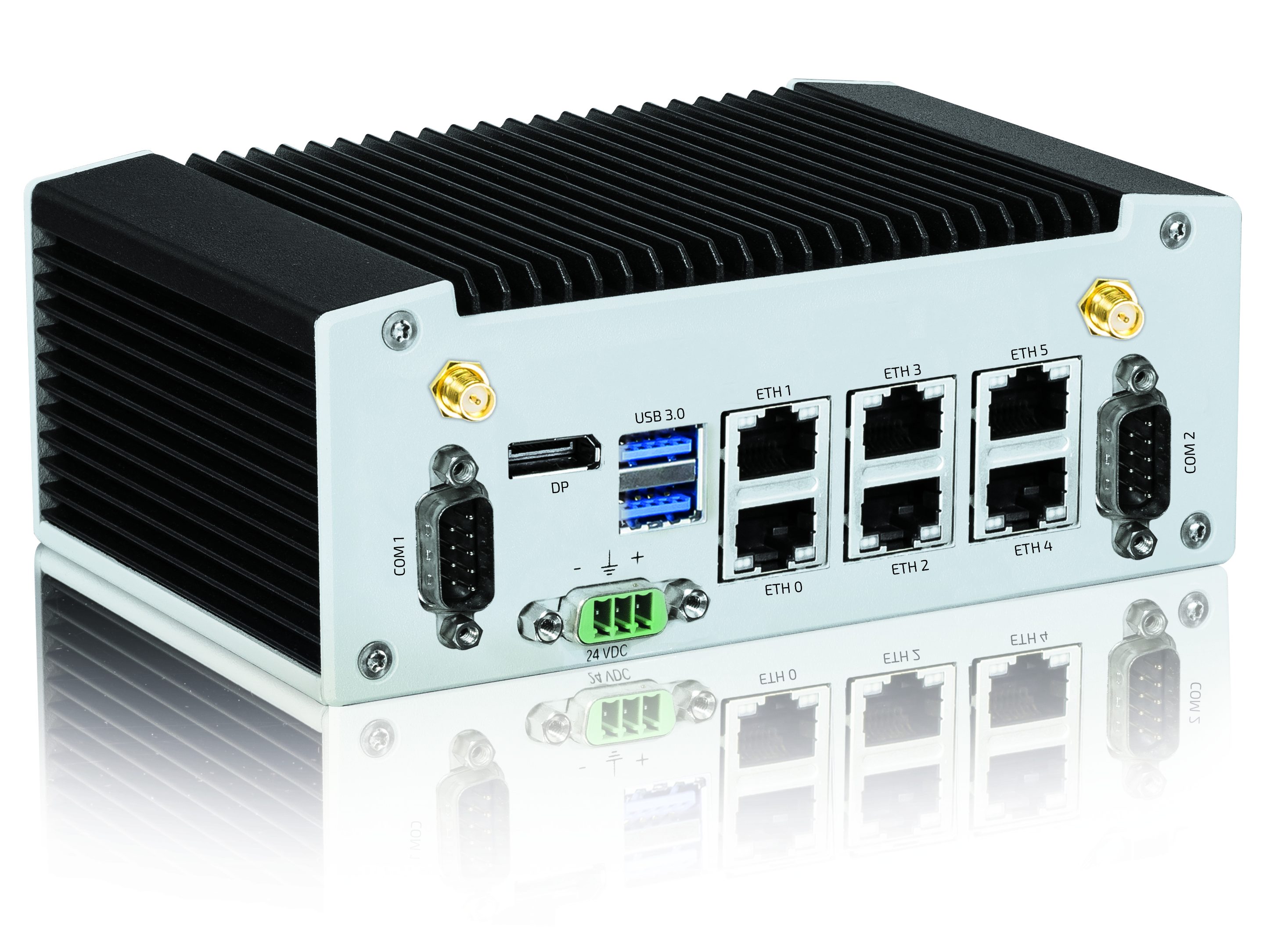
Kontron, a leading global provider of IoT/Embedded Computing Technology (ECT), has announced the KBox A-230-LS, a new compact industrial computer platform designed specifically for Time Sensitive Networking (TSN) applications. The KBox A-230-LS is equipped with a SMARC module based on the NXP Dual Cortex A72 LS1028 processor. The SMARC-sAL28 module offers up to five integrated TSN-enabled 1GB Ethernet ports directly from the controller and fulfills the specifications of the TSN standard IEEE 802.1, making the KBox A-230-LS ideal for use in industrial IoT environments based on Ethernet protocol standards.
The compact, fanless KBox A-230-LS is designed for a variety of industrial applications. The two Arm® v8 processor cores both support real-time processing in industrial control systems and virtual machines for edge computing within the IoT. The CPU includes integrated GPU and LCD controllers, enabling the realization of HMI systems.
The compact KBox A-230-LS offers numerous interfaces that facilitate the connection to different communication levels. A serial interface (RS232/RS485 and optional CAN) enables local data acquisition and connection to the sensor or machine environment. The integration into the IT environment can be achieved via Gigabit Ethernet interfaces. In addition to a regular 1GB Ethernet interface, a total of up to five TSN-capable 1GB Ethernet ports are available. Furthermore, the KBox A-230-LS has a DisplayPort connection, an USB 3.0 and an USB 2.0 interface.
The KBox A-230-LS is equipped with an NXP Dual Cortex A72 LS1028 processor. It supports up to 4GB DDR3L with ECC and has an eMMC onboard flash memory with up to 64GB. Additional storage media are a mSATA SDD, a M.2 SSD or a microSD card. System extensions can be implemented via a MiniPCI Express or M.2 interface.
The KBox A-230-LS is quick and easy to deploy, making it ideal for OEMs and system integrators who want to exploit the full potential of the next generation of intelligent infrastructures in the IoT environment. The KBox A-230-LS is also certified for Microsoft Azure and works ideal with Microsoft Azure IoT Services.
Like all box PCs within the Kontron KBox A-series, the KBox A-230-LS is maintenance-free, as the system is fanless and battery-free. Linux Yocto is used as the operating system. In addition, the KBox A-230-LS optionally supports the Kontron APPROTECT security solution powered by Wibu-Systems. The integrated security chip from Wibu-Systems in combination with a suitable software framework protects IP rights and provides copy and reverse engineering protection. Kontron APPROTECT Licensing also enables new business models such as ‘pay per use’. Moreover, time based trial versions or activating / deactivating functions are offered as well.
Home automation refers to the ability of your home to make its own decisions depending on environment conditions and give you the option to control it from a remote location. In one of our previous tutorial on the ESP8266 WiFi Module, we examined how NodeMCU or any of the other ESP8266 based boards can be used to build a web server through which all the GPIOs of the board can be controlled over WiFi. Today, we are going to put that web server in use and control home appliances with it.
Home Automation using NodeMCU (ESP8266) board – [Link]
Home automation refers to the ability of your home to make its own decisions depending on environment conditions and give you the option to control it from a remote location. In one of our previous tutorial on the ESP8266 WiFi Module, we examined how NodeMCU or any of the other ESP8266 based boards can be used to build a web server through which all the GPIOs of the board can be controlled over WiFi. Today, we are going to put that web server in use and control home appliances with it.
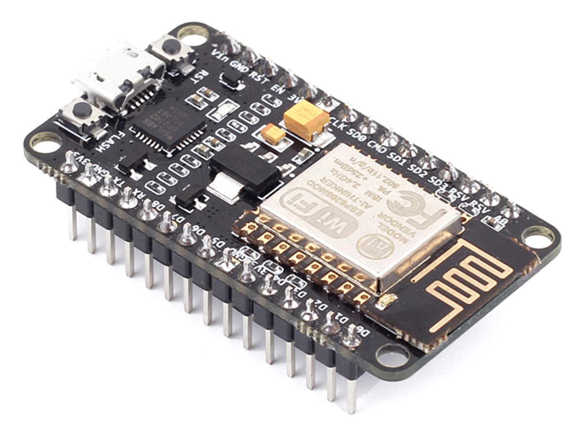
NodeMCU Development Board
The heart of today’s project is the WiFi enabled board that needs no introduction; the ESP8266 based NodeMCUdevelopment board. It is an open source platform for developing WiFi based embedded systems and it is based on the popular ESP8266 WiFi Module, running the Lua based NodeMCU firmware. NodeMCU was born out of the desire to overcome the limitations associated with the first versions of the ESP8266 module which was not compatible with breadboards, it was difficult to power and even more difficult to program. The NodeMCU board is easy to use, low cost and that quickly endeared it to the heart of makers and it is one of the most popular boards today.
For today’s tutorial, we will add a 2-channel relay module to the ESP8266 board. The project flow involves the control of NodeMCU’s GPIOs from a webpage on any device connected on the same network as the board. The status of the GPIOs control the coils of the relays and that causes the relay to alternate between normally open (NO) and normally closed (NC) condition depending on the state of the GPIO, thus, effectively turning the connected appliance “ON” or “OFF”.
It’s important to note that, connecting the appliances to the relay involves interaction with AC voltages which could be dangerous. Ensure you have experience interacting with AC voltages and do so in a safe manner.
Required Components
The following components are required to build this project:
NodeMCU (ESP8266-12E)
2-Channel Relay Module
Breadboard
Jumper Wire
For those who don’t have access to a relay module, you can use 2x single channel relay modules or single relays with the supporting transistor circuitry. For that purpose you will additionally need:
5v Relays (2)
2N2222 Transistor (2)
1N4007 Diode (2)
220 ohms resistor (2)
5V battery/PSU
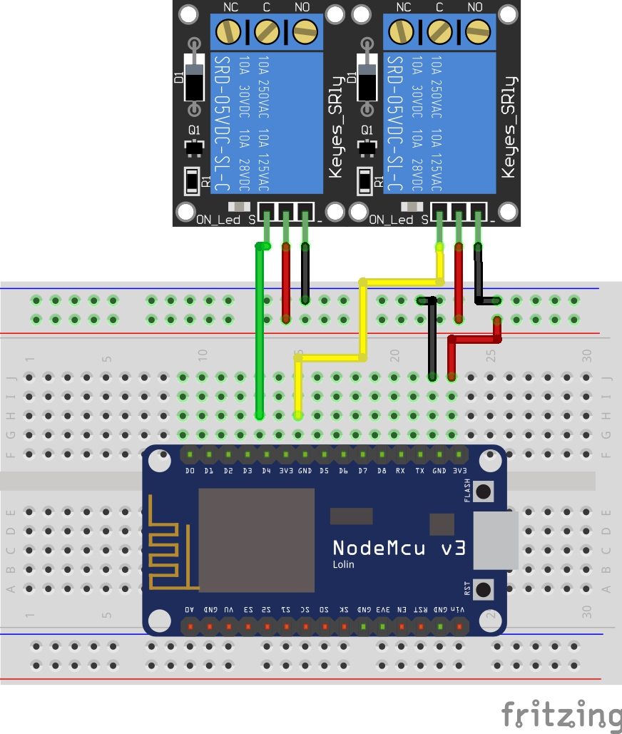
Schematics
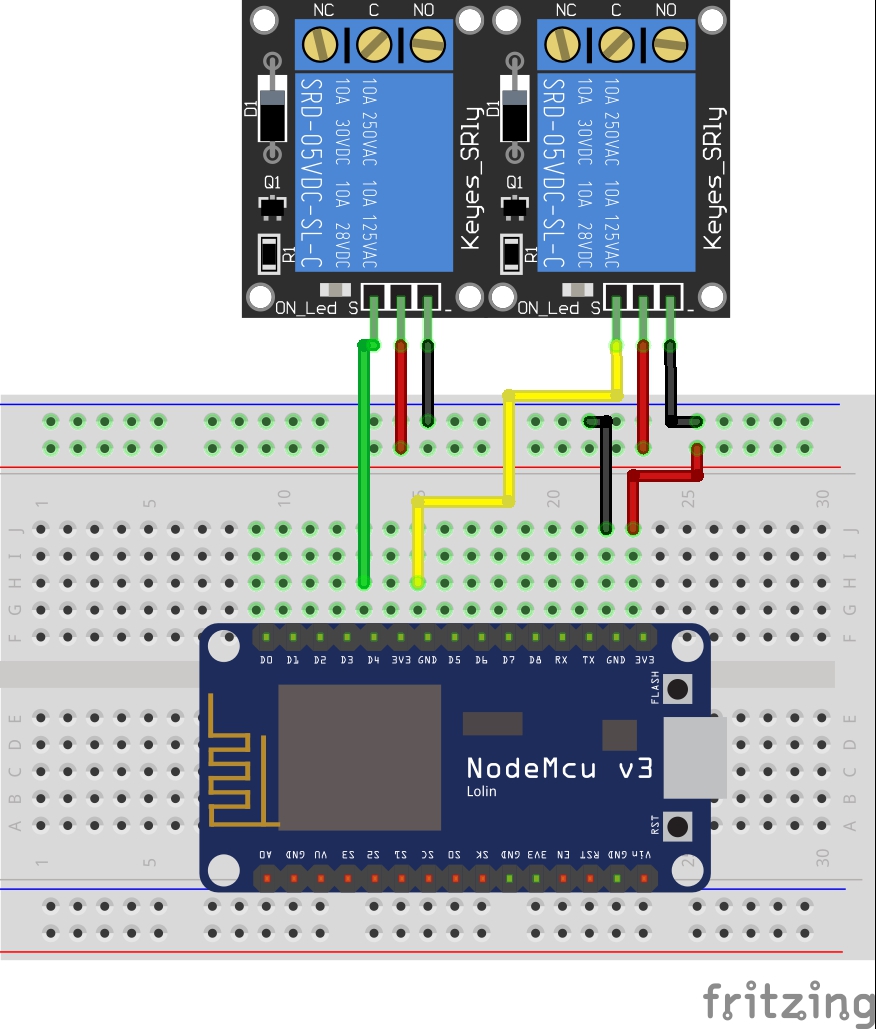
The schematics for this project is quite simple. Connect the components as shown in the diagram below.
Schematics
To make the connections easy to follow, here is a pin map of the connection between NodeMCU and the relay module.
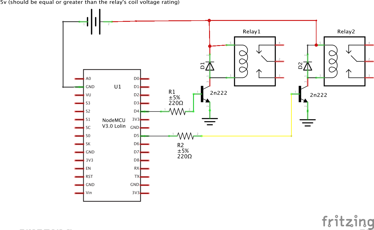
If you are using the ordinary relays without the module supporting circuit, connect the relays to the NodeMCU as shown below. Ensure the relay’s coils are rated 5v or change the 5v supply to match your relay’s rated coil voltage.
Schematics 2
With the schematics done, we can then move forward to write the code for the project.
Code
One of the easiest way to program NodeMCU is via the Arduino IDE. This, however, requires setting up the Arduino IDE by installing the board support file for NodeMCU. If you are using the Arduino IDE to program the NodeMCU for the first time, you need to do this first before proceeding with this tutorial. Follow the detailed tutorial “Getting Started with the NodeMCU” to learn how to set up your Arduino IDE to program ESP8266 based boards.
The code for today’s tutorial is a modified version of the code from the last article “NodeMCU ESP8266 WebServer Tutorial“. The code is based on the ESP8266WiFi.h library which allows the easy use of WiFi functionalities of the board. It contains all we need to create or join a WiFi access point and also create a server and client which are all important for today’s project. The library comes attached with the NodeMCU board files for the Arduino, so there is no need to install it once the board files have been installed.
The code for today’s tutorial will enable us to control appliances connected to the GPIOs (via relays) of the NodeMCU board remotely.
To start with, we include the library that we will use for the project, which in this case, is the ESP8266WiFi.h library.
#include <ESP8266WiFi.h>
Next, we add the credentials of the WiFi access point to which the NodeMCU will be connected. Ensure the username and password are between the double quotes. We also specify the port through which the system will communicate and create a variable to hold requests.
// Add wifi access point credentiaals
const char* ssid     = "xxxxx";
const char* password = "xxxx";

WiFiServer server(80);// Set port to 80
Next, we declare the pins of the Nodemcu to which the relay pins are connected and create variables to hold the state of each relay.
// Declare the pins to which the appliances are connected via relays
int app1 = D1; //appliance 1
int app2 = D2; //appliance 2`
//you can add more more appliances below.

String app1state = "off";// state of appliance1
String app2state = "off";// state of appliance2
Next is the void setup() function. We start by initializing the serial monitor (as it will be used for debugging later on) and setting the pinModes of the pins to which the relays are connected as output. We then set the pins “LOW” to ensure the system starts at OFF state.
void setup() {
  Serial.begin(115200);
 // Set the pinmode of the pins to which the LEDs are connected and turn them low to prevent flunctuations
  pinMode(app1, OUTPUT);
  pinMode(app2, OUTPUT);
  digitalWrite(app1, LOW);
  digitalWrite(app2, LOW);
Next, we connect to the access point using the credentials provided as arguments to the WiFi.begin() function and we use the WiFi.status() function to check if connection was successful. The system will keep trying until the connection is successful.
//connect to access point
  WiFi.begin(ssid, password);
  Serial.print("Connecting to ");
  Serial.println(ssid);
  while (WiFi.status() != WL_CONNECTED) {
    delay(500);
    Serial.print(".");
  }
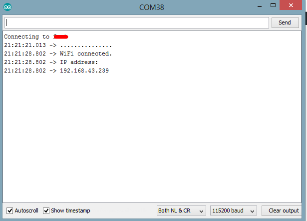
If the connection is successful, a text is printed on the serial monitor to indicate this, along with the IP address of the NodeMCU. This IP address becomes the web address for the server and should be entered on any web browser on the same network as the server so we are able to access it.
// Print local IP address and start web server
  Serial.println("");
  Serial.println("WiFi connected.");
  Serial.println("IP address: ");
  Serial.println(WiFi.localIP());// this will display the Ip address of the Pi which should be entered into your browse
}
Next, we start the server using the server.begin() function.
server.begin();
}
Next, we write the void loop() function. This is where a bulk of the work is done. We start by using the server.available() function to listen for incoming connections by clients (web browsers). When a client is available and connected, we read the client request and send a header as a response.
void loop(){
  WiFiClient client = server.available();   // Listen for incoming clients

  if (client) {                             // If a new client connects,
    String currentLine = "";                // make a String to hold incoming data from the client
    while (client.connected()) {            // loop while the client's connected
      if (client.available()) {             // if there's bytes to read from the client,
        char c = client.read();             // read a byte, then
        Serial.write(c);                    // print it out the serial monitor
        header += c;
        if (c == '\n') {                    // if the byte is a newline character
          // if the current line is blank, you got two newline characters in a row.
          // that's the end of the client HTTP request, so send a response:
          if (currentLine.length() == 0) {
            // HTTP headers always start with a response code (e.g. HTTP/1.1 200 OK)
            // and a content-type so the client knows what's coming, then a blank line:
            client.println("HTTP/1.1 200 OK");
            client.println("Content-type:text/html");
            client.println("Connection: close");
            client.println();
Next, the client’s request is examined to see if it indicates a button press on the web page. If it does, the state of the GPIO is changed accordingly to the request. If the request indicates “ON”, the pin is turned HIGH and the state variable is updated accordingly.
// turns the GPIOs on and off
           if (header.indexOf("GET /app1/on") >= 0) {
             Serial.println("App 1 on");
             app1state = "on";
             digitalWrite(app1, HIGH);
           } else if (header.indexOf("GET /app1/off") >= 0) {
             Serial.println("App 1 off");
             app1state = "off";
             digitalWrite(app1, LOW);
           } else if (header.indexOf("GET /app2/on") >= 0) {
             Serial.println("App 2 on");
             app2state = "on";
             digitalWrite(app2, HIGH);
           } else if (header.indexOf("GET /app2/off") >= 0) {
             Serial.println("App 2 off");
             app2state = "off";
             digitalWrite(app2, LOW);
           }
Next, we create the webpage that will be displayed and updated by the NodeMCU as the user interacts with it. The key function for this is the Client.println() function which is used to send HTML scripts line by line to the client.
We start by indicating that the next few texts to be printed are HTML lines as declaring by doctype.
client.println("<!DOCTYPE html><html>");
Next, we add the lines below to make webpage responsive irrespective of the browser being used.
Next, the webpage header is sent followed by the buttons and the buttons are set to display the current state of the appliances. They will show OFF if the current state is ON and vice versa.
client.println("<body><h1>ESP8266 Web Server</h1>");
// Display current state, and ON/OFF buttons for GPIO 5
client.println("<p>app1 - State " + app1state + "</p>");
// If Appliance 1 is off, it displays the ON button
if (app1state == "off") {
client.println("<p><a href=\"/app1/on\"><button class=\"button\">ON</button></a></p>");
} else {
client.println("<p><a href=\"/app1/off\"><button class=\"button button2\">OFF</button></a></p>");
}
// Display current state, and ON/OFF buttons for GPIO 4
client.println("<p>app2 - State " + app2state + "</p>");
// If Appliance 2 is off, it displays the ON button
if (app2state == "off") {
client.println("<p><a href=\"/app2/on\"><button class=\"button\">ON</button></a></p>");
} else {
client.println("<p><a href=\"/app2/off\"><button class=\"button button2\">OFF</button></a></p>");
}
client.println("</body></html>");
// The HTTP response ends with another blank line
client.println();
// Break out of the while loop
break;
} else { // if you got a newline, then clear currentLine
currentLine = "";
}
} else if (c != '\r') { // if you got anything else but a carriage return character,
currentLine += c; // add it to the end of the currentLine
}
}
}
Next, we close the connection and the flow goes back to the top.
The complete code for the project is available below and also attached under the download section.
#include <ESP8266WiFi.h>
// Add wifi access point credentiaals
const char* ssid = "xxxx";
const char* password = "xxxxx";
WiFiServer server(80);// Set port to 80
String header; // This storees the HTTP request
// Declare the pins to which the appliances are connected via relays
int app1 = D1; //appliance 1
int app2 = D2; //appliance 2`
//you can add more more appliances below.
String app1state = "off";// state of appliance1
String app2state = "off";// state of appliance2
void setup() {
Serial.begin(115200);
// Set the pinmode of the pins to which the LEDs are connected and turn them low to prevent flunctuations
pinMode(app1, OUTPUT);
pinMode(app2, OUTPUT);
digitalWrite(app1, LOW);
digitalWrite(app2, LOW);
//connect to access point
WiFi.begin(ssid, password);
Serial.print("Connecting to ");
Serial.println(ssid);
while (WiFi.status() != WL_CONNECTED) {
delay(500);
Serial.print(".");
}
// Print local IP address and start web server
Serial.println("");
Serial.println("WiFi connected.");
Serial.println("IP address: ");
Serial.println(WiFi.localIP());// this will display the Ip address of the Pi which should be entered into your browser
server.begin();
}
void loop(){
WiFiClient client = server.available(); // Listen for incoming clients
if (client) { // If a new client connects,
String currentLine = ""; // make a String to hold incoming data from the client
while (client.connected()) { // loop while the client's connected
if (client.available()) { // if there's bytes to read from the client,
char c = client.read(); // read a byte, then
Serial.write(c); // print it out the serial monitor
header += c;
if (c == '\n') { // if the byte is a newline character
// if the current line is blank, you got two newline characters in a row.
// that's the end of the client HTTP request, so send a response:
if (currentLine.length() == 0) {
// HTTP headers always start with a response code (e.g. HTTP/1.1 200 OK)
// and a content-type so the client knows what's coming, then a blank line:
client.println("HTTP/1.1 200 OK");
client.println("Content-type:text/html");
client.println("Connection: close");
client.println();
// turns the GPIOs on and off
if (header.indexOf("GET /app1/on") >= 0) {
Serial.println("App 1 on");
app1state = "on";
digitalWrite(app1, HIGH);
} else if (header.indexOf("GET /app1/off") >= 0) {
Serial.println("App 1 off");
app1state = "off";
digitalWrite(app1, LOW);
} else if (header.indexOf("GET /app2/on") >= 0) {
Serial.println("App 2 on");
app2state = "on";
digitalWrite(app2, HIGH);
} else if (header.indexOf("GET /app2/off") >= 0) {
Serial.println("App 2 off");
app2state = "off";
digitalWrite(app2, LOW);
}
// Display the HTML web page
client.println("<!DOCTYPE html><html>");
client.println("<head><meta name=\"viewport\" content=\"width=device-width, initial-scale=1\">");
client.println("<link rel=\"icon\" href=\"data:,\">");
// CSS to style the on/off buttons
// Feel free to change the background-color and font-size attributes to fit your preferences
client.println("<style>html { font-family: Helvetica; display: inline-block; margin: 0px auto; text-align: center;}");
            client.println(".button { background-color: #195B6A; border: none; color: white; padding: 16px 40px;");
            client.println("text-decoration: none; font-size: 30px; margin: 2px; cursor: pointer;}");
            client.println(".button2 {background-color: #77878A;}</style></head>");
// Web Page Heading
client.println("<body><h1>ESP8266 Web Server</h1>");

            // Display current state, and ON/OFF buttons for GPIO 5
            client.println("<p>app1 - State " + app1state + "</p>");
            // If Appliance 1 is off, it displays the ON button
            if (app1state == "off") {
              client.println("<p><a href=\"/app1/on\"><button class=\"button\">ON</button></a></p>");
            } else {
              client.println("<p><a href=\"/app1/off\"><button class=\"button button2\">OFF</button></a></p>");
            }

            // Display current state, and ON/OFF buttons for GPIO 4
            client.println("<p>app2 - State " + app2state + "</p>");
            // If Appliance 2 is off, it displays the ON button
            if (app2state == "off") {
              client.println("<p><a href=\"/app2/on\"><button class=\"button\">ON</button></a></p>");
            } else {
              client.println("<p><a href=\"/app2/off\"><button class=\"button button2\">OFF</button></a></p>");
            }
            client.println("</body></html>");

            // The HTTP response ends with another blank line
            client.println();
            // Break out of the while loop
            break;
          } else { // if you got a newline, then clear currentLine
            currentLine = "";
          }
        } else if (c != '\r') {  // if you got anything else but a carriage return character,
          currentLine += c;      // add it to the end of the currentLine
        }
      }
    }
// Clear the header variable
header = "";
// Close the connection
 client.stop();
    Serial.println("Client disconnected.");
    Serial.println("");
  }
}
Demo
Upload the code to the NodeMCU. Ensure everything is connected as described under the schematics section. After uploading the code, you should see the IP address of your web server displayed in the serial monitor as shown below.
Arduino Serial Terminal Output
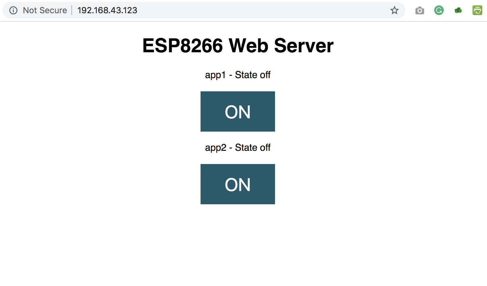
Copy the IP address and paste it in a web browser on any device (Mobile or PC) connected to the same network as the NodeMCU. You should see the web page and be able to toggle the connected appliances by clicking the buttons.
Web Server interface
That’s it for this tutorial. Thanks for reading.
As mentioned above, this tutorial could serve as a building block for more complex web servers and IoT solutions. What will you build?
If you have any question about today’s tutorial, please feel free to share via the comment section.