VAMRS has designed a new version of their board with the launch of the Rock960 model C, that is much cheaper than the early Rockchip RK3399 Rock960 board and still compliant to 96Board’s specifications without losing out in performance.
In comparison with last year prices, 96Boards compliant Rock960 board was sold for $99 and up. It had these main features: Rockchip RK3399 processor, up to 4GBRAM, up to 32GB eMMC flash. But now the prices have drastically been cut down to about $69 after much intimidation from the cheaper FriendlyElec NanoPi NEO4 board.
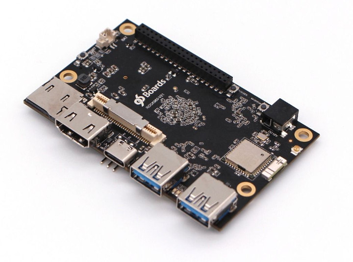
Rock960 Model C
Rock960 model C is equipped with 1, 2 or 4GB LPDDR4 RAM, and the OS can boot from a micro SD card or an optional eMMC flash module. A good temptation might be to compare to the cheaper FriendlyElec NanoPi NEO4 board, although they offer similar specifications, the NanoPi NEO4 board is only available in a 1GB RAM alone. Also, it doesn’t have its own inbuilt storage, so microSD card is a must for running the OS.
Rock960 model C specifications:
Dimensions: 85 x 54mm
Weight: 120grams
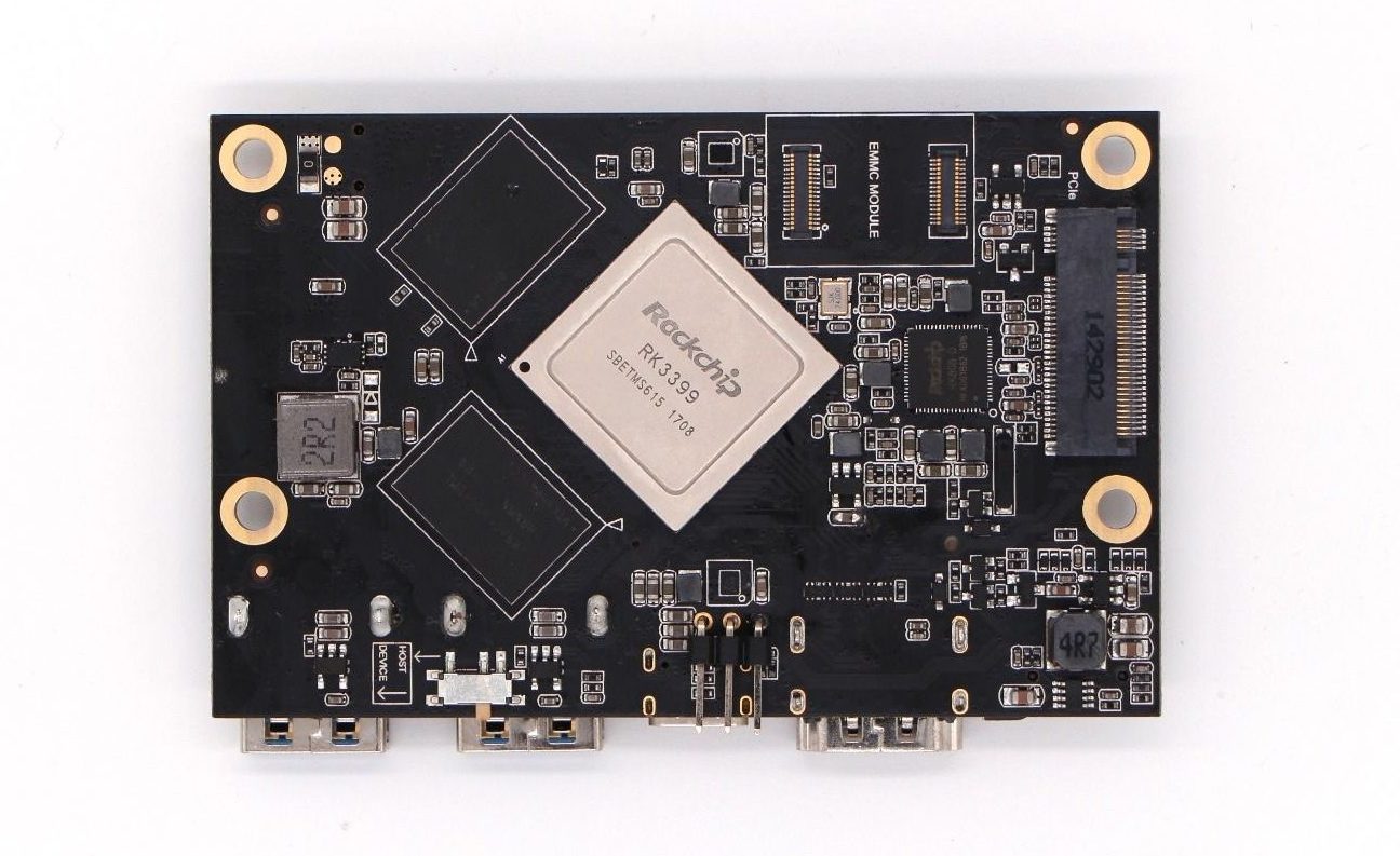
SoC – Rochchip RK3399 hexa-core big.LITTLE processor with 2x Cortex A72 cores up to 1.8/2.0 GHz, 4x Cortex A53 cores @ 1.4 GHz, and an Arm Mali-T860 MP4 GPU with OpenGL ES 1.1 to 3.2, OpenVG1.1, OpenCL 1.2 and DX 11 support
RAM / System Memory: Available in 1, 2 or 4GB LPDDR4
Storage memory: micro SD card and eMMC flash socket.
Video Output: 1x HDMI 2.0 up to 4K@60 Hz with CEC and HDCP
6 LEDS
Power Supply: 12 V input
Connectivity:
WiFi 802.11ac 2×2 MIMO up to 867 Mbps up to 200 Mbps,
Bluetooth 4.2 LE with two onboard antennas, two u.FL antenna connectors
USB: 1x USB 2.0 type-C port, that is host only & 2x USB 3.0 ports, these are one OTG and one host only
Other changes, which have been made into new models are related to connectivity, memory, storage, USB ports. In connectivity, 2×2 MIMO has been downgraded. Type C USB ports are also replaced with USB 2.0. While USB 2.0 type-A port is upgraded to a USB 3.0 port. Thermal adaptations are also much better; a heatsink covers the bottom of the board. That provides a better cooling solution.
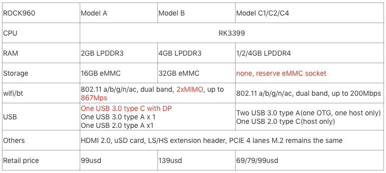
Model Comparison
Packaging list:
ROCK960 model C board
12V/2A Power adapter
Acrylic case Heatsink with glue screws
The boards are available for purchase online from SeedStudio and directly from VARMS store. 1 GB model is now available for $69, while the subsequent models for 2 GB RAM have a price tag of $79, while the 4 GB of $99.
The new board can run AOSP, Debian, Ubuntu, Fedora, LibreELEC, Lakka or FlintOS, and all documentation for Rock960 model C can be found on 96boards website, where they also refer to the board as Rock960c.
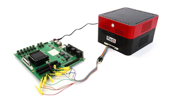
Redd is a remote development device targeted at embedded projects. Using Redd, you can easily program devices remotely, as if they were sitting right in front of you. Simply connect using OpenVPN tunnel, and start developing.
Redd is equipped with the most common interfaces for embedded device programming:
USB 2.0 x2
Low Current Relay x6
switched SD card
switched SPI flash
I/O controlled FPGA with Voltage Regulator Selection x8 (universal I / O port)
The project is going to be launched soon on www.crowdsupply.com. If you want to get notified when the project launched, you can subscribe to the available form.
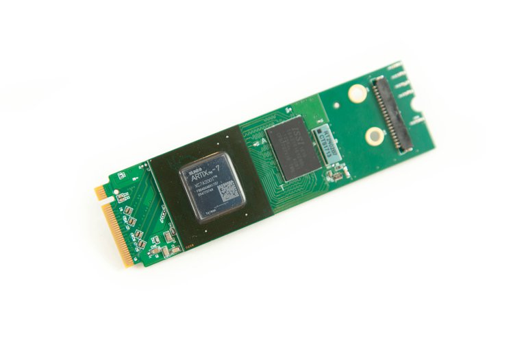
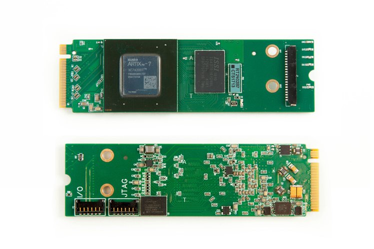
An Artix-7 FPGA with its own DDR3 RAM right in your laptop – for developing PCIe, etc.
NiteFury is an Artix-7 FPGA development board in an M.2 form-factor that includes on-board DDR3 RAM. This combination lets you work with PCI Express at incredible rates from inside your laptop or desktop. You can also use NiteFury as an FPGA co-processor. Let Xilinx’s largest Artix-7 handle your encryption or act as a hardware-level encoder/decoder for speedy workflows. It’s your FPGA, design what you like.
NiteFury Features
Giant FPGA: NiteFury features the largest Artix-series part that Xilinx makes. It has six times the processing power of PicoEVB. It uses the Xilinx A200T FPGA at just under 1000 GMAC/s.
On-board RAM: The faster you process with an Artix-7, the more you may need to store. The on-board DDR3, 4 Gb (512 MB x 16) RAM keeps data within arms reach and takes the burden off your computer.
Popular Form Factor: NiteFury fits in the M.2 M key slot, which is popular in laptops today. This slot features 4x PCIe for high bandwidth (2 GB/s). Why keep your FPGA on your desk when you can take it with you?
Affordable: Buying the Xilinx Artix-7 XC7A200T FPGA alone would generally cost around $250. By teaming up with another company, NiteFury gives you all that power with little additional cost (especially during the campaign).
Expandable: With twelve external I/O in total, four of which are selectable as either analog or digital, you aren’t just confined to interfacing via computer. The connectors used in the design are easy to find Pico-EZmates and a DF52.
The project is live on crowdsupply.com and has 42 days left to be funded. For $329 your get the original NiteFury, with the largest Artix FPGA and 4 Gb DDR3.
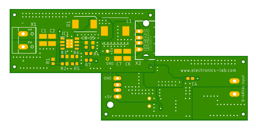
We recently placed an order on JLCPCB.com for 5 pieces of a PCB design we have done here at electronics-lab.com. The project we were dealing is a 60V to 5V @ 3.5A buck converter based on TPS54360B and we are going to publish it soon under Projects -> Power. The PCB design has 2 layers and was done on Autodesk Eagle. In this post we will discuss, how to export the Gerber files from Autodesk Eagle, how to place an order on JLCPCB, how much was the delivery time, unboxing of PCBs and quality inspection.
Autodesk Eagle Gerber export for JLCPCB.com
The Gerber export was straight forward. All we have to do is to hit the “CAM Processor” button, make sure “template_2_layer.cam” is loaded, then select “Gerber” on the list at the left and change Output Type to Gerber RS-274X. After that, click on the “+” sign below left list and select “New Gerber Output“, change the Name and Description to “Vias” and add “Viaslayer” on the list below. Check export as Zip, then Process Job and save the output file to your preferred location. You should get a message “Job Processed Succesfully“.
If you want to go the fast way, you can download JLCPCB.zip which contains all the necessary changes for the CAM Processor in a single .cam file. You just have to load it by clicking “Load Job File” and process the job.
Please note, that Drill file is generated along with the Gerbers and is included in the resulting .zip
Export Gerbers from AutoDesk Eagle
Placing an order on JLCPCB.com
Now, that you have the Gerber files exported, you can easily upload them to the JLCPCB website and get a quote. Once uploaded to their website, the interface will detect the size of the board and display the thumbnail of it, just to verify everything is as you expect. The cost for 5 small size PCBs is only 2 USD with build time 2-3 days and 4x delivery options. The fasted of them is via DHL and costs $23. With this option selected you will get your boards in 3-5 business days. We placed our order on 26/02/2019 and we received them through DHL on 05/03/2019, that’s a total of 7 days and that’s pretty quick in most cases.
Order placement on JLCPCB.com
Received PCBs from JLCPCB.com – Unboxing and first impressions
As said before, manufacturing and delivery time was 7 days in total and that is pretty impressive. But let’s see what we got. The PCBs where packaged on a cartoon box and inside plastic air tight pack. Let’s see the unboxing.
The PCBs look well manufactured and quality is good enough as for the first impression.
A closer inspection on the PCBs
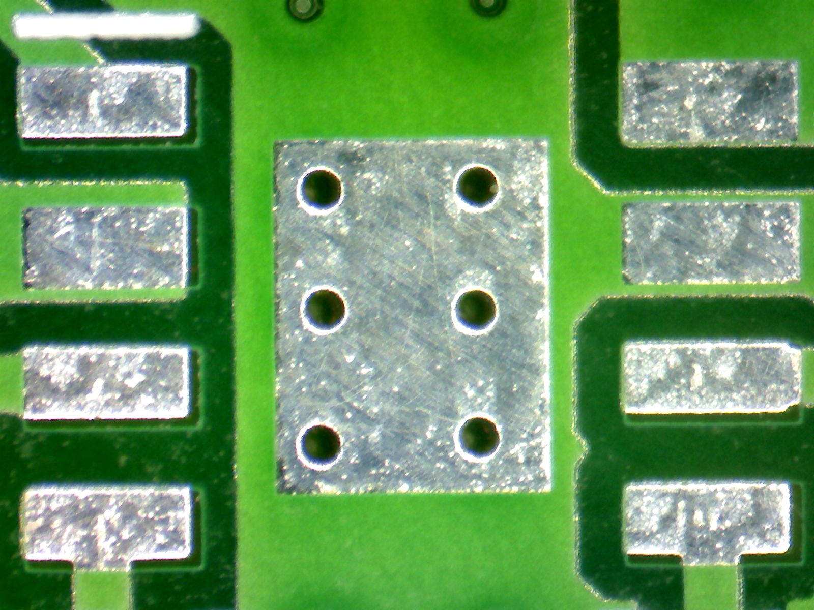
Let’s do a closer inspection of the manufacturing quality of the PCBs received. To do this we will use a microscope to get the details. First we will check the soldermask and Vias alignment. As you can see on the photo below, there is a small misalignment of the soldermask on top of solder pads. This is more noticeable on the first and last pads. Also there is a significant misalignment on the vias on the large thermal pad under the IC. These are expected not to affect the performance of the board but they are an indicator of the manufacturing process.
Soldermask and vias alignment
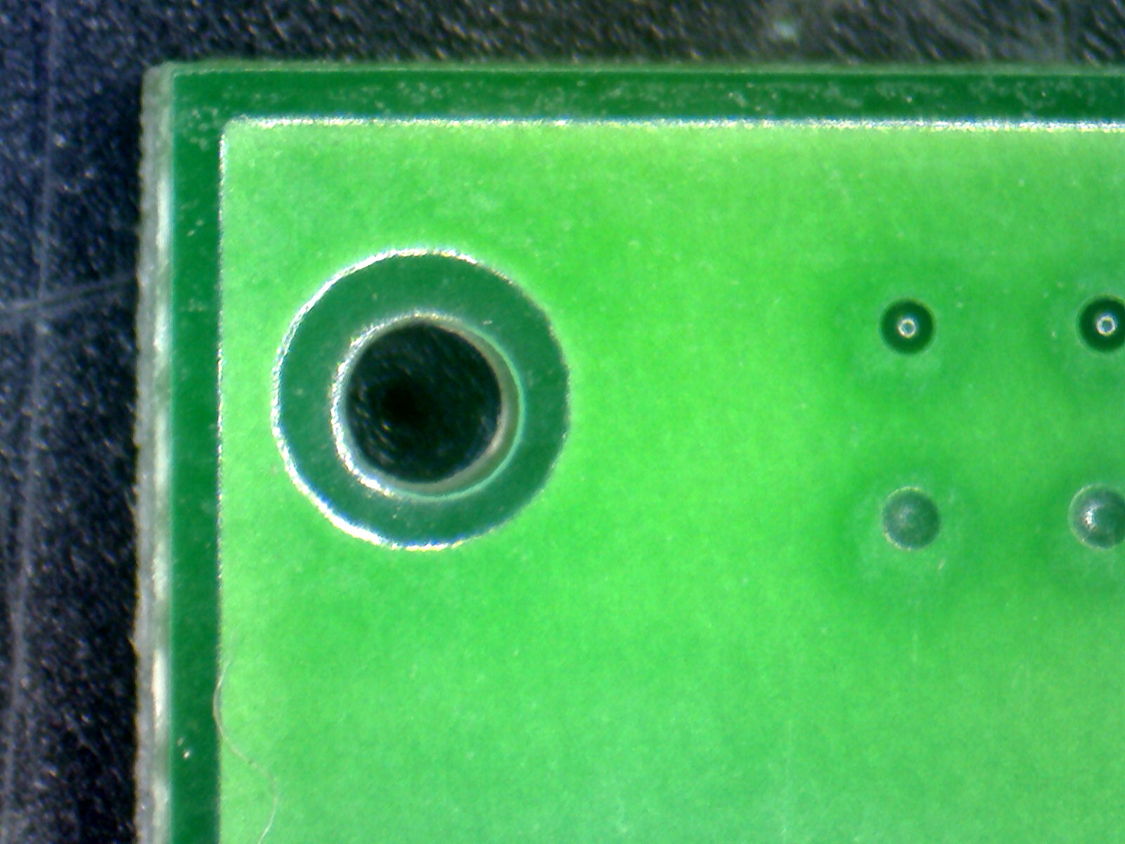
Next, we will take a look on the edges of the PCB and the drills on the corners. As you can see on the photo below copper alignment on the edges is almost perfect and has the same distance from the end of board in the x and y dimensions. Regarding the hole, there is a small misalignment of the drill as it is a little off the center. This again is not going to affect the assembly of the board but this may be something to consider if high precision is required.
Hole alignment and PCB edges
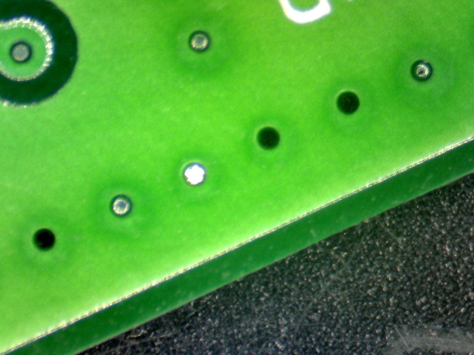
The next photo shows the tended Vias on the ground plane. As you can see, some of them contain solder and solder mask residues. This is caused because the drills are small (0.4mm) and keep excess material. We suppose this will not happen in bigger vias.
Tended Vias on ground plane
On the next photo we take a look for the e-test marks. We only found these marks on the bottom layer and only on 2 of the pads. This is supposed to be fully tested using flying probes.
The last photo shows a bump (of copper ?) under the solder mask and this was present on all the 5 pieces we got. The bump wasn’t something on the design and is probably a defect of the manufacture. This has not affected the functionality of the PCB, but this is something caused by uncontrolled process and depends on the spot it appears. If this was on a trace of via it may caused a short circuit.
A bump appears under solder mask
Conclusion
This was our first order from JLCPCB and we are mostly happy with it. The overall impression of ordering and receiving the PCBs from JLCPCB.com was positive, considering the price tag for the PCBs and shipping costs with DHL. The overall cost for 5 PCBs delivered was €23. Their web interface was easy and straight forward to use and we hadn’t any difficulty placing the order. The Gerber preview works as expected, producing a good render of the board to be manufactured. Manufacturing time and delivery was impressive and quality was acceptable for the scope of our projects. You may need to consider the manufacturing defects on higher precision boards, but in any case this is a value for money, no doubt. We would suggest to give it a try yourself and why not leave your feedback below.
From the Wemos D1 mini to the NodeMCU, the ESP8266 based boards are by far the most popular platform, among makers and hobbyist, for building WiFi based projects due to their low cost and general ease of use. For today’s tutorial, we will continue our exploration of the most popular of the ESP8266 based boards; the NodeMCU development board and we will explore how to build a web server using it. Through the web server, we will be able to control anything connected to the GPIO pins of the board. We will not limit ourselves to just controlling LEDs, but by expanding this project you can build a full-blown home automation system or any other project that involves controlling or obtaining data from the NodeMCU’s GPIO remotely.
From the Wemos D1 mini to the NodeMCU, the ESP8266 based boards are by far the most popular platform, among makers and hobbyist, for building WiFi based projects due to their low cost and general ease of use. For today’s tutorial, we will continue our exploration of the most popular of the ESP8266 based boards; the NodeMCU development board and we will explore how to build a web server using it. Through the web server, we will be able to control anything connected to the GPIO pins of the board. We will not limit ourselves to just controlling LEDs, but by expanding this project you can build a full-blown home automation system or any other project that involves controlling or obtaining data from the NodeMCU’s GPIO remotely.
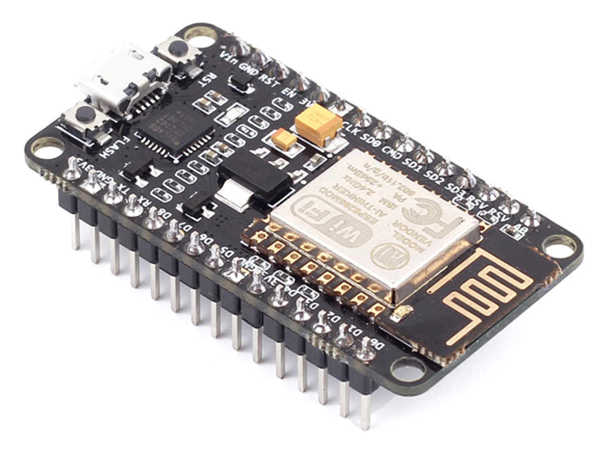
NodeMCU Development Board
The NodeMCU development board is an open source platform for developing WiFi based embedded devices. It is based on the ESP8266WiFi Module and runs the Lua based NodeMCU firmware. The NodeMCU was born out of the desire to overcome all the bottlenecks associated with the first versions of the ESP8266 module which was not compatible with breadboards, difficult to power and even more difficult to program. Its ease of use and low cost, quickly endeared it to the heart of makers and it is one of the most popular boards today.
At the end of today’s tutorial, you would know how to use the NodeMCU as a web server and how to control the GPIO pins of your NodeMCU/ESP8266 board from a webpage.
Required Components
The following components are required to build this project;
NodeMCU (ESP8266-12E)
220 ohms Resistor(2)
LED (2)
Breadboard
Jumper Wire
Schematics
The schematic for this project is quite simple. As mentioned earlier, we will toggle LEDs to demonstrate what can be achieved using the NodeMCU Web server. While LEDs are being used here, you can decide to use more useful components like a relay, which could then be used to control appliances in your home.
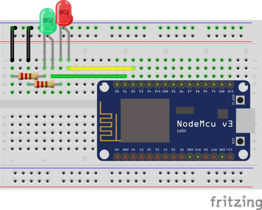
Connect the components as shown in the schematics below.
Schematics
The positive legs of the green and red LEDs are connected to digital pins 1 and 2 of the NodeMCU (respectively), while their negative legs are connected to ground via a 220 ohms resistor to limit the amount of current flowing through the LEDs.
With the schematics done, we can now move to the code for the project.
Code
One of the easiest ways to program the NodeMCU is via the Arduino IDE. However, this requires setting up the Arduino IDE by installing the board support file for NodeMCU. If you are using the Arduino IDE to program the NodeMCU for the first time, you need to do this first before proceeding with the tutorial. Follow this detailed tutorial to learn how to set up your Arduino to program ESP8266 based boards.
With that done, we can now move to the code. The main driver behind today’s tutorial is the ESP8266WiFi Library. This library contains cool functions to implement WiFi based activities and project on the NodeMCU. It contains all we need to create a WiFi access point or join up with an existing access point and also create a server and client which are all important for today’s project. The libraries come attached with the NodeMCU board files for the Arduino, so there is no need to install them once the board files have been installed.
As mentioned above, our goal is to create a web server through which the GPIOs of the NodeMCU can be controlled. The Web server should be accessible via a browser on any device on the same network as the NodeMCU.
The code for this project is a modified version of the code by Rui Santos (credits for him). It’s a little bit complex and might be difficult to follow for those without the knowledge of HTML but I will do my best to break it down.
To start, as usual, we include the library that will be used for the code which in this case, is the ESP8266wifi library.
#include <ESP8266WiFi.h>
Next, add the credentials of the WiFi access point to which the NodeMCU will be connected. Ensure the username and password are in-between the double quotes. We also specify the port through which the system will communicate and create a variable to hold requests.
const char* ssid     = "WIFI_SSID";
const char* password = "WIFI_PASSWORD";

WiFiServer server(80);// Set port to 80


String header; // This storees the HTTP request
Next, we declare the pins of the Nodemcu to which the red and green LED will be connected and create variables to hold the state of the LEDs.
int greenled = D1;
int redled = D2;

String greenstate = "off";// state of green LED
String redstate = "off";// state of red LED
With this done, we move to the void setup() function.
We start by initializing the serial monitor (as it will be used for debugging later on) and setting the pinModes of the pins to which the LEDs are connected as output. We then set the pins “LOW” to ensure the system starts at a neutral state.
void setup() {
  Serial.begin(115200);
 // Set the pinmode of the pins to which the LEDs are connected and turn them low to prevent flunctuations
  pinMode(greenled, OUTPUT);
  pinMode(redled, OUTPUT);
  digitalWrite(greenled, LOW);
  digitalWrite(redled, LOW);
Next, we connect to the access point using the credentials as arguments to the WiFi.begin() function and we use the WiFi.status() function to check if connection was successful.
WiFi.begin(ssid, password);
Serial.print("Connecting to ");
Serial.println(ssid);
while (WiFi.status() != WL_CONNECTED) {
  delay(500);
  Serial.print(".");
}
If the connection is successful, a text is printed on the serial monitor to indicate that, and the IP address of the web server is also displayed. This IP address becomes the web address for server and it is what will be entered on any web browser on the same network to access the server.
Serial.println("");
  Serial.println("WiFi connected.");
  Serial.println("IP address: ");
  Serial.println(WiFi.localIP());// this will display the Ip address of the Pi which should be entered into your browser
With that done, we start the server using the server.begin() function and proceed to the void loop( ) function.
server.begin();
The void loop() function is where the majority of the work is done. We start by using the server.available() function to listen for incoming connection by clients (web browsers). When a client is available and connected, we read the client request and send the header as a response.
WiFiClient client = server.available();   // Listen for incoming clients

  if (client) {                             // If a new client connects,
    String currentLine = "";                // make a String to hold incoming data from the client
    while (client.connected()) {            // loop while the client's connected
      if (client.available()) {             // if there's bytes to read from the client,
        char c = client.read();             // read a byte, then
        Serial.write(c);                    // print it out the serial monitor
        header += c;
        if (c == '\n') {                    // if the byte is a newline character
          // if the current line is blank, you got two newline characters in a row.
          // that's the end of the client HTTP request, so send a response:
          if (currentLine.length() == 0) {
            // HTTP headers always start with a response code (e.g. HTTP/1.1 200 OK)
            // and a content-type so the client knows what's coming, then a blank line:
            client.println("HTTP/1.1 200 OK");
            client.println("Content-type:text/html");
            client.println("Connection: close");
            client.println();
Next, we check if the client’s request indicates a button press on the web page, to turn any of the pins “on/off” starting with the green LED. If the request indicates “on”, the pin is turned high and the state variable is updated accordingly and vice versa.
// turns the GPIOs on and off
           if (header.indexOf("GET /green/on") >= 0) {
             Serial.println("green on");
             greenstate = "on";
             digitalWrite(greenled, HIGH);
           } else if (header.indexOf("GET /green/off") >= 0) {
             Serial.println("green off");
             greenstate = "off";
             digitalWrite(greenled, LOW);
           } else if (header.indexOf("GET /red/on") >= 0) {
             Serial.println("red on");
             redstate = "on";
             digitalWrite(redled, HIGH);
           } else if (header.indexOf("GET /red/off") >= 0) {
             Serial.println("red off");
             redstate = "off";
             digitalWrite(redled, LOW);
           }
Next, we create the webpage that will be displayed and updated by the NodeMCU as the user interacts with it. The key function for this is the Client.println() function which is used to send HTML scripts line by line to the client (browser).
we start by using the “doctype” to indicate that the next few texts to be printed are HTML lines.
client.println("<!DOCTYPE html><html>");
Next, we add the lines below to make webpage responsive irrespective of the browser being used
Next, the webpage header is sent alongside the buttons which are set to display on or off based on the current state of the LED. It will display off if the current state is ON and vice versa.
client.println("<body><h1>ESP8266 Web Server</h1>");
// Display current state, and ON/OFF buttons for GPIO 5
client.println("<p>green - State " + greenstate + "</p>");
// If the green LED is off, it displays the ON button
if (greenstate == "off") {
client.println("<p><a href=\"/green/on\"><button class=\"button\">ON</button></a></p>");
} else {
client.println("<p><a href=\"/green/off\"><button class=\"button button2\">OFF</button></a></p>");
}
// Display current state, and ON/OFF buttons for GPIO 4
client.println("<p>red - State " + redstate + "</p>");
// If the red LED is off, it displays the ON button
if (redstate == "off") {
client.println("<p><a href=\"/red/on\"><button class=\"button\">ON</button></a></p>");
} else {
client.println("<p><a href=\"/red/off\"><button class=\"button button2\">OFF</button></a></p>");
}
client.println("</body></html>");
Next, we close the connection and the loop goes over again.
// Clear the header variable
header = "";
// Close the connection
client.stop();
Serial.println("Client disconnected.");
Serial.println("");
The complete code for the project is shown below and also available for download under the download section at the end of the tutorial.
#include <ESP8266WiFi.h>
// Add wifi access point credentiaals
const char* ssid = "WIFI_SSID";
const char* password = "WIFI_PASSWORD";
WiFiServer server(80);// Set port to 80
String header; // This storees the HTTP request
// Declare the pins to which the LEDs are connected
int greenled = D1;
int redled = D2;
String greenstate = "off";// state of green LED
String redstate = "off";// state of red LED
void setup() {
Serial.begin(115200);
// Set the pinmode of the pins to which the LEDs are connected and turn them low to prevent flunctuations
pinMode(greenled, OUTPUT);
pinMode(redled, OUTPUT);
digitalWrite(greenled, LOW);
digitalWrite(redled, LOW);
//connect to access point
WiFi.begin(ssid, password);
Serial.print("Connecting to ");
Serial.println(ssid);
while (WiFi.status() != WL_CONNECTED) {
delay(500);
Serial.print(".");
}
// Print local IP address and start web server
Serial.println("");
Serial.println("WiFi connected.");
Serial.println("IP address: ");
Serial.println(WiFi.localIP());// this will display the Ip address of the Pi which should be entered into your browser
server.begin();
}
void loop(){
WiFiClient client = server.available(); // Listen for incoming clients
if (client) { // If a new client connects,
String currentLine = ""; // make a String to hold incoming data from the client
while (client.connected()) { // loop while the client's connected
if (client.available()) { // if there's bytes to read from the client,
char c = client.read(); // read a byte, then
Serial.write(c); // print it out the serial monitor
header += c;
if (c == '\n') { // if the byte is a newline character
// if the current line is blank, you got two newline characters in a row.
// that's the end of the client HTTP request, so send a response:
if (currentLine.length() == 0) {
// HTTP headers always start with a response code (e.g. HTTP/1.1 200 OK)
// and a content-type so the client knows what's coming, then a blank line:
client.println("HTTP/1.1 200 OK");
client.println("Content-type:text/html");
client.println("Connection: close");
client.println();
// turns the GPIOs on and off
if (header.indexOf("GET /green/on") >= 0) {
Serial.println("green on");
greenstate = "on";
digitalWrite(greenled, HIGH);
} else if (header.indexOf("GET /green/off") >= 0) {
Serial.println("green off");
greenstate = "off";
digitalWrite(greenled, LOW);
} else if (header.indexOf("GET /red/on") >= 0) {
Serial.println("red on");
redstate = "on";
digitalWrite(redled, HIGH);
} else if (header.indexOf("GET /red/off") >= 0) {
Serial.println("red off");
redstate = "off";
digitalWrite(redled, LOW);
}
// Display the HTML web page
client.println("<!DOCTYPE html><html>");
client.println("<head><meta name=\"viewport\" content=\"width=device-width, initial-scale=1\">");
client.println("<link rel=\"icon\" href=\"data:,\">");
// CSS to style the on/off buttons
// Feel free to change the background-color and font-size attributes to fit your preferences
client.println("<style>html { font-family: Helvetica; display: inline-block; margin: 0px auto; text-align: center;}");
client.println(".button { background-color: #195B6A; border: none; color: white; padding: 16px 40px;");
client.println("text-decoration: none; font-size: 30px; margin: 2px; cursor: pointer;}");
client.println(".button2 {background-color: #77878A;}</style></head>");
// Web Page Heading
client.println("<body><h1>ESP8266 Web Server</h1>");

// Display current state, and ON/OFF buttons for GPIO 5
client.println("<p>green - State " + greenstate + "</p>");
// If the green LED is off, it displays the ON button
if (greenstate == "off") {
  client.println("<p><a href=\"/green/on\"><button class=\"button\">ON</button></a></p>");
} else {
  client.println("<p><a href=\"/green/off\"><button class=\"button button2\">OFF</button></a></p>");
}

// Display current state, and ON/OFF buttons for GPIO 4
client.println("<p>red - State " + redstate + "</p>");
// If the red LED is off, it displays the ON button
if (redstate == "off") {
  client.println("<p><a href=\"/red/on\"><button class=\"button\">ON</button></a></p>");
} else {
  client.println("<p><a href=\"/red/off\"><button class=\"button button2\">OFF</button></a></p>");
}
client.println("</body></html>");
// The HTTP response ends with another blank line
client.println();
// Break out of the while loop
break;
} else { // if you got a newline, then clear currentLine
currentLine = "";
}
} else if (c != '\r') { // if you got anything else but a carriage return character,
currentLine += c; // add it to the end of the currentLine
}
}
}
// Clear the header variable
header = "";
// Close the connection
client.stop();
Serial.println("Client disconnected.");
Serial.println("");
}
}
Demo
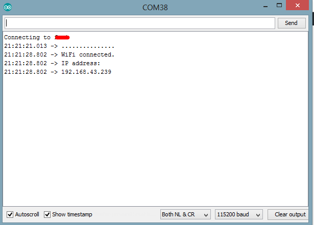
Upload the code to your NodeMCU. Ensure everything is connected as described under the schematics section. After uploading the code, open the serial monitor, you should see the IP address of your web server displayed, as shown below.
The IP Address
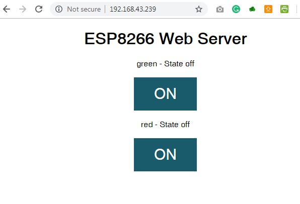
Copy the IP address and paste in a web browser on a device connected to the same network as the NodeMCU. You should see the web page and be able to toggle the LEDs by clicking on the buttons.
Demo: Click the buttons to change the states of the LEDs
That’s it for this tutorial, Thanks for reading.
As mentioned above, this tutorial could serve as a building block for complex web servers and IoT solutions. What will you build?
If you have any question about today’s tutorial, please feel free to share via the comment section.
Coilcraft will introduce its new XGL4020 Series of high-performance, molded power inductors at the upcoming Applied Power Electronics Conference (APEC), March 17-21 in Anaheim, CA. The XGL4020 features the industry’s lowest DC losses and extremely low AC losses for a wide range of DC-DC converters (from hundreds kHz up to 5+ MHz). Additional performance improvements include a wider range of inductance values and improved Irms current ratings.
The XGL4020 is available in twelve inductance values from 0.33 to 8.2 µH, with current ratings up to 15.2 Amps and soft saturation characteristics. It offers the lowest DC resistance currently available in the market – up to 45% lower than Coilcraft’s next lowest soft-saturation products. The lower DCR and higher Irms also allow the XGL4020 to operate much cooler than other components.
XGL4020 Series inductors are qualified to AEC-Q200 Grade 1 standards (-40° to +125°C ambient) with a maximum part temperature of +165°C and exhibit no thermal aging issues, making them suitable for automotive and other harsh-environment applications. They feature RoHS-compliant, tin-silver-over-copper terminations and are halogen free. Their composite construction also minimizes audible buzzing.
The composite construction of both products results in soft saturation characteristics, allowing them to withstand high current spikes. They exhibit no thermal aging issues, and their construction also minimizes audible buzzing.
As with all Coilcraft parts, free evaluation samples of the XGL4020 Series are available online at www.coilcraft.com
Like previously marketed boards of Raspberry, this new module is not meant for the traditional use. Rather, business and industrial use were intended with the New Raspberry Pi Compute Module 3+. Keeping the same compatibility, Raspberry new boards are the modern version of computing modules. For sure, development in the old system is always needed, so is the board’s industry. Coping up with the demand of the industry, the new modules have made users optimistic regarding their system.
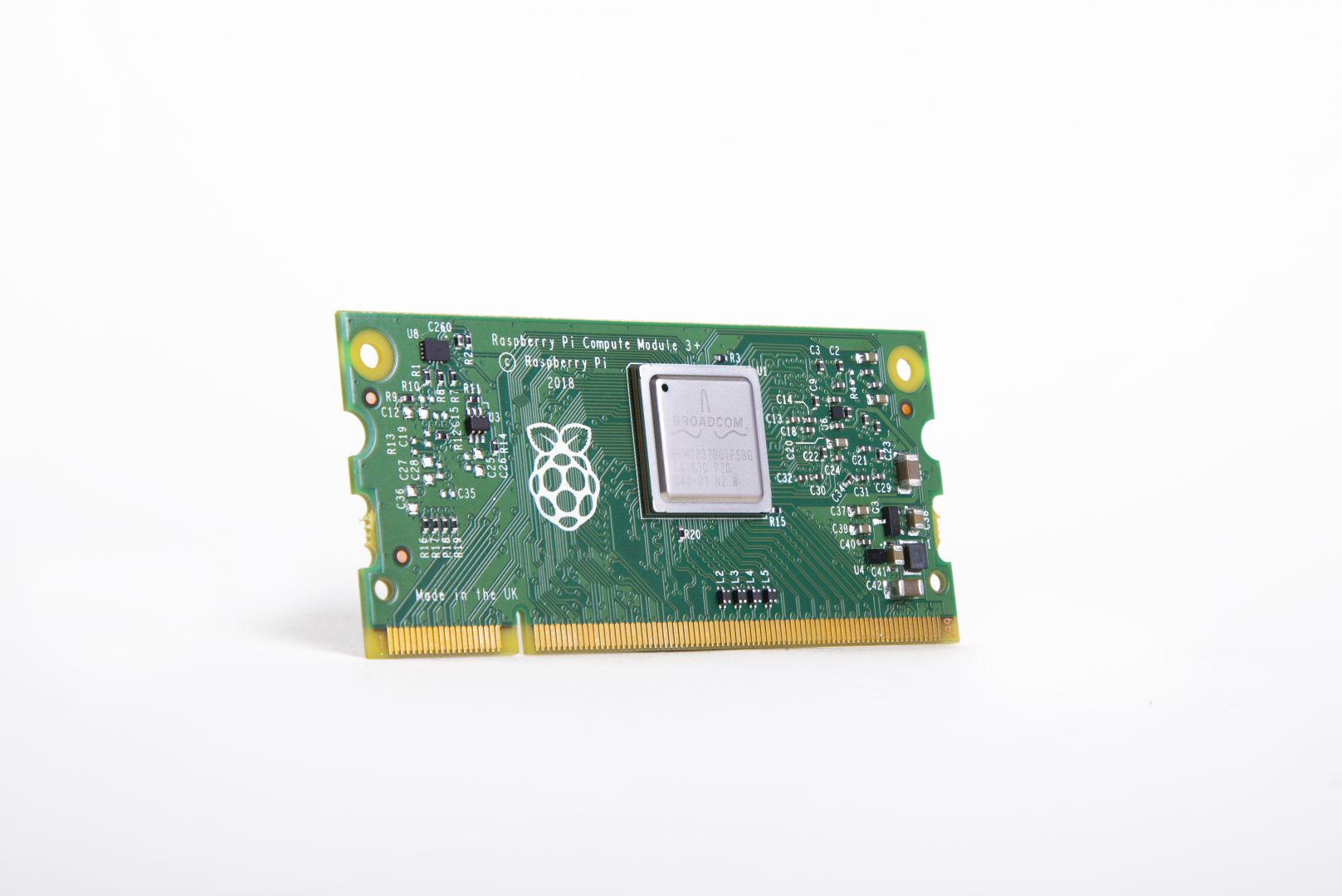
Raspberry Pi Compute Module 3+
Packed in a similar 67.6 x 31mm SODIMM styled module, the new compute module is built around the same Broadcom BCM2837B0 processor that is used on the Raspberry Pi 3, Model B+ and A+ boards but unlike the Model B+ and A+, the processor speed is clocked at 1.2GHz found on the previous compute module rather than the speedier 1.4GHz, and this decision is believed to be related to power supply limitations. Just like it’s predecessor, the CM+ continues to offer 1GB of LPDDR2 RAM and lacks the RPI 3 modules built-in WiFi and Bluetooth radios.
“…Compute Module 3+ is an evolution of Compute Module 3 and [original] Compute Module, bringing new features while keeping the form factor, electrical compatibility, price point, and ease of use of the earlier products.”—James Adams, COO Raspberry Pi Trading
One major upgrade for the CM+ is the better thermal control. To overcome the heating issues, it has refined the thermal control system. So long lasting processing is an utmost feature of Pi compute Module 3+. In opting for the best feature for business and industry purpose, perhaps this is a first requirement to have increased thermal capacity.
“The Compute Module also provides more interfaces than the regular Raspberry Pi, supporting two cameras and two displays, as well as extra GPIO.”
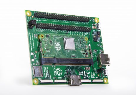
Raspberry Pi Compute Module 3+ Development Kit
Raspberry also offers a development kit which is expected to be open source. The refreshed development kit will include 1 × Lite and 1 × 32GB Compute Module 3+ modules, along with the Compute Module IO board, camera, and display adapters, jumper wires, and a programming cable.
The Raspberry Pi Compute Module 3+ is available in the following configurations: Lite/no eMMC ($25), 8GB eMMC ($30), 16GB ($35), and 32GB ($40). More information may be found at the Raspberry Pi Foundation’s RPi CM3+ announcement and datasheet, and the Newark Element14 CM3+ shopping page. More on the dev kit may be found at the CM3+ Development Kit product page.
Weather stations are interesting projects for beginners and very useful for expert makers. They are usually quite simple to build but also provide fairly accurate and useful weather data. We have built a couple of them in different tutorials on this website, with the difference usually being, the combinations and sometimes the accuracy of the sensors used. For today’s tutorial, we will build another weather station, but this time, we will use the BMP280 sensor as the primary one and we will be able to monitor temperature, atmospheric pressure, and altitude.
The BMP280 is the next-generation sensors from Bosch and it is an upgrade to their previous range of sensors including the BMP085, BMP180, and the BMP183. The BMP280 is great for all sorts of weather sensing with a low altitude noise of 0.25m and the same fast conversion rate as the previous sensors. In addition, the BMP280 can be used in both I2C and SPI mode and the sensor board version from Adafruit has a 3.3v voltage regulator and level shifter on board which means it can be used with either 3.3v or 5v voltage supply.
Weather stations are interesting projects for beginners and very useful for expert makers. They are usually quite simple to build but also provide fairly accurate and useful weather data. We have built a couple of them in different tutorials on this website, with the difference usually being, the combinations and sometimes the accuracy of the sensors used. For today’s tutorial, we will build another weather station, but this time, we will use the BMP280 sensor as the primary one and we will be able to monitor temperature, atmospheric pressure, and altitude.
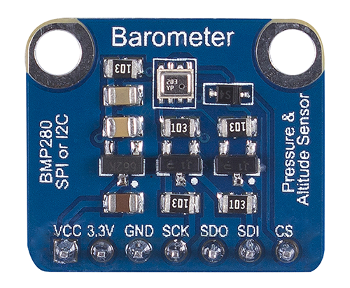
BMP280 Sensor board
The BMP280 is the next-generation sensors from Bosch and it is an upgrade to their previous range of sensors including the BMP085, BMP180, and the BMP183. The BMP280 is great for all sorts of weather sensing with a low altitude noise of 0.25m and the same fast conversion rate as the previous sensors. In addition, the BMP280 can be used in both I2C and SPI mode and the sensor board version from Adafruit has a 3.3v voltage regulator and level shifter on board which means it can be used with either 3.3v or 5v voltage supply.
Along with the BMP280, we will use the I2C-based, 128×32 OLED from Adafruit to show the values obtained from the BMP280 sensor. At the end of today’s tutorial, you would know how to use the BMP280 or any other i2c device with the Arduino and also know how to display data on an OLED display using the Arduino.
Required Components
The following components are required to build this project;
The exact components used for this tutorial can be bought via the link attached to each of the components above.
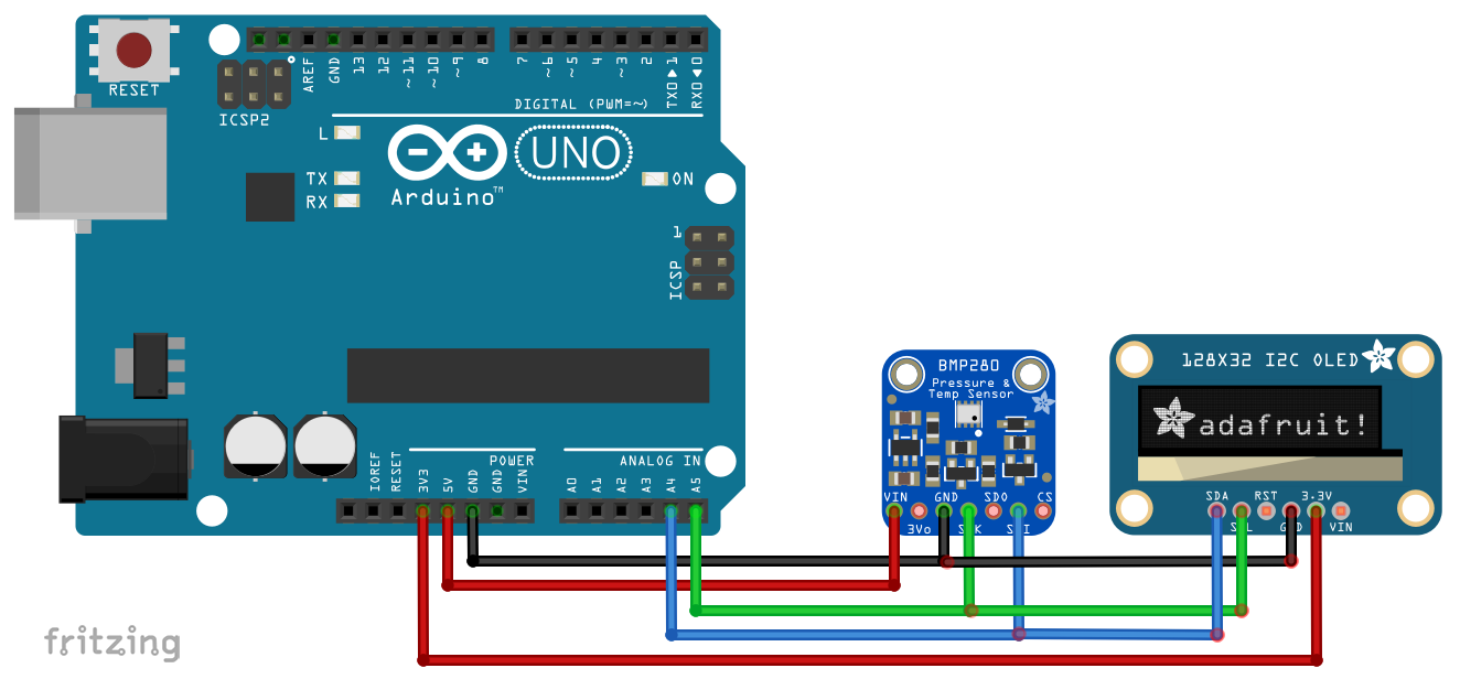
Schematics
The schematic for this project is quite easy. The 128×32 OLED and the BMP280 both communicate with the Arduino via I2C, this means, they will be connected to the same pins (I2C) on the Arduino. Connect the components as shown in the schematics below.
Schematics
To make the connections easier to follow, here is a pin map showing how each of the components connects to the Arduino.
Arduino – BMP280
5V - vin
GND - GND
A4 - SDA
A5 - SCL
Arduino – OLED
3.3V - 3.3V
GND - GND
A4 - SDA
A5 - SCL
Go over the schematics once more to ensure everything is properly connected.
Code
To write the code for this project, we will use three key libraries; the Adafruit BMP280 library, the Adafruit GFX library and the Adafruit SSD1306 library. The three libraries can be downloaded via the Arduino Library Manager or via the download link attached to them.
The Adafruit BMP280 contains functions that make it easy to write the code that will obtain the parameters from the sensor while the Adafruit GFX and SSD1306 libraries are used to easily display texts and graphics on the OLED.
I will do a run through of the entire code and will try to explain as much as possible.
We start the code by including the libraries that we will use on the project after which we specify the dimensions (width = 128, height =32) of the OLED display and declare the pin of the Arduino to which the reset pin of the OLED is connected.
Next, we create a class of the OLED library with the dimensions as arguments and also create a class of the BMP280 library.
Adafruit_SSD1306 display(SCREEN_WIDTH, SCREEN_HEIGHT, &Wire, OLED_RESET); //Declaring the display name (display)
Adafruit_BMP280 bmp;
Next, we write the void setup() function. We start by initializing the BMP using the bmp.begin() command and we also start communications with the OLED using the display.begin() function to get it started.
void setup() {
  bmp.begin();                                //Start the bmp
  display.begin(SSD1306_SWITCHCAPVCC, 0x3C); //Start the OLED display
With the initializations done, we set the color (using display.setTextColor function), set the font size (using the display.setTextSize() function), and display a welcome message (using the display.print() function). Feel free to change the displayed text as desired
display.clearDisplay();
  display.display();
  display.setTextColor(WHITE);
  display.setTextSize(1);
  display.print("SurtrTech");     //Show the name, you can remove it or replace it
  display.setCursor(32,12);
  display.setTextSize(2);
  display.println("BMP280");
  display.display();
  delay(2000);
}
With this done, we move to the void loop function(). We start by clearing the display (using the display.clearDisplay() function) after which we read the temperature, pressure and altitude, storing them into the variables T, P, and A respectively.
void loop() {

    display.clearDisplay();
    float T = bmp.readTemperature();           //Read temperature in C
    float P = bmp.readPressure()/100;         //Read Pressure in Pa and conversion to hPa
    float A = bmp.readAltitude(1019.66);      //Calculating the Altitude, the "1019.66" is the pressure in (hPa) at sea level at day in your region
Next, we display the measured parameters using the display.setCursor() function to effectively divide the OLED screen so they are all displayed at once. After this, we use the display.display() function to apply changes on the OLED. A time delay of 2000ms is set to ensure the values stay long enough on the display to be seen before they are replaced by new values.
display.setCursor(0,0);                   //Oled display, just playing with text size and cursor to get the display you want
    display.setTextColor(WHITE);
    display.setTextSize(2);
    display.print("Temp");

    display.setCursor(0,18);
    display.print(T,1);
    display.setCursor(50,17);
    display.setTextSize(1);
    display.print("C");

    display.setTextSize(1);
    display.setCursor(65,0);
    display.print("Pres");
    display.setCursor(65,10);
    display.print(P);
    display.setCursor(110,10);
    display.print("hPa");

    display.setCursor(65,25);
    display.print("Alt");
    display.setCursor(90,25);
    display.print(A,0);
    display.setCursor(110,25);
    display.print("m");

    display.display();
    delay(2000);
}
The complete code for the project is provided below and also attached under the download section of the tutorial.
#include <Adafruit_GFX.h>      //Libraries for the OLED and BMP280
#include <Adafruit_SSD1306.h>
#include <Adafruit_BMP280.h>

#define SCREEN_WIDTH 128 // OLED display width, in pixels
#define SCREEN_HEIGHT 32 // OLED display height, in pixels
#define OLED_RESET    -1 // Reset pin # (or -1 if sharing Arduino reset pin)

Adafruit_SSD1306 display(SCREEN_WIDTH, SCREEN_HEIGHT, &Wire, OLED_RESET); //Declaring the display name (display)
Adafruit_BMP280 bmp;

void setup() {
  bmp.begin();                                //Start the bmp
  display.begin(SSD1306_SWITCHCAPVCC, 0x3C); //Start the OLED display
  display.clearDisplay();
  display.display();
  display.setTextColor(WHITE);
  display.setTextSize(1);
  display.print("SurtrTech");     //Show the name, you can remove it or replace it
  display.setCursor(32,12);
  display.setTextSize(2);
  display.println("BMP280");
  display.display();
  delay(2000);
}

void loop() {

    display.clearDisplay();
    float T = bmp.readTemperature();           //Read temperature in C
    float P = bmp.readPressure()/100;         //Read Pressure in Pa and conversion to hPa
    float A = bmp.readAltitude(1019.66);      //Calculating the Altitude, the "1019.66" is the pressure in (hPa) at sea level at day in your region
                                              //If you don't know it just modify it until you get the altitude of your place

    display.setCursor(0,0);                   //Oled display, just playing with text size and cursor to get the display you want
    display.setTextColor(WHITE);
    display.setTextSize(2);
    display.print("Temp");

    display.setCursor(0,18);
    display.print(T,1);
    display.setCursor(50,17);
    display.setTextSize(1);
    display.print("C");

    display.setTextSize(1);
    display.setCursor(65,0);
    display.print("Pres");
    display.setCursor(65,10);
    display.print(P);
    display.setCursor(110,10);
    display.print("hPa");

    display.setCursor(65,25);
    display.print("Alt");
    display.setCursor(90,25);
    display.print(A,0);
    display.setCursor(110,25);
    display.print("m");

    display.display();
    delay(2000);
}
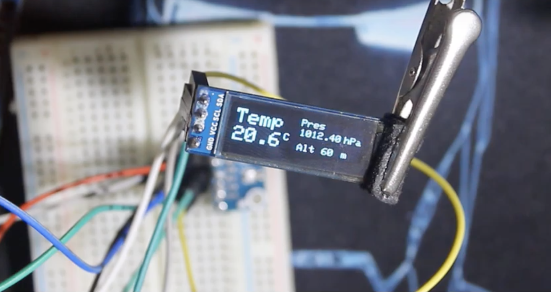
Demo
Go over the setup in the schematics to ensure you connected everything as described then upload the code to your Arduino. You should see the display come as shown in the image below after a while.
That’s all guys. Are you working on a quadcopter and want to add an additional sensor to determine altitude or you are just building a standard weather station and you need to add temperature and pressure, this might just be the sensor for you.
Feel free to reach out via the comment section if you have any difficulty getting things to work.