Low power Arm-based i.MX6 Cortex®-A9 processor with soldered-on RAM, Gigabit Ethernet, Wi-Fi, Bluetooth® and fanless operation.
The Swordtail single board computer is a complete Wi-Fi and Bluetooth®enabled, Arm®-based embedded computer. Models are available with power-efficient, dual-core or quad-core i.MX6 CPUs. These boards are designed for applications that demand rugged, power-efficient solutions such as industrial machine automation, transportation, medical, kiosk, and industrial IoT applications. Swordtail boards have been designed to enable transactions and transmission of maintenance or diagnostic information without the presence of a wired data connection. Both Wi-Fi and Bluetooth radios are included on board, and a NimbleLinkSkywire™ socket supports a wide range of optional cellular and other wireless plug-ins.
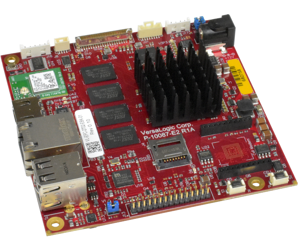
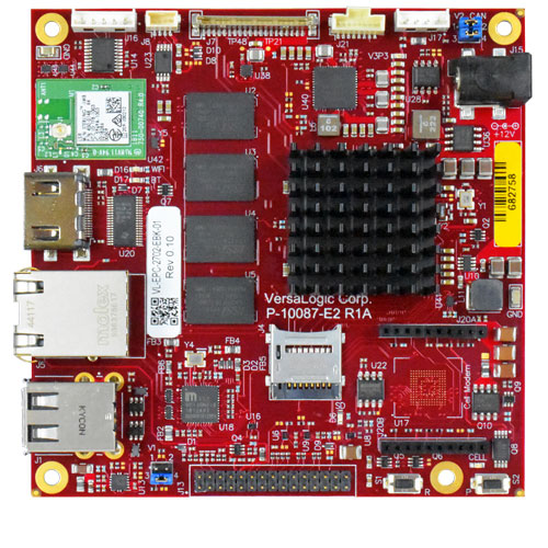
Versalogic Swordtail SBC
Unlike Arm-based “modules”, Swordtail is a complete board-level computer. Additional carrier boards, connector boards, or I/O expansion boards are not required for operation. Swordtail boards are delivered with on-board soldered-down RAM, ready to plug-in and run. To simplify mounting and future upgrades, the Swordtail leverages the COM-Express standard for its footprint and mounting points.
The following specifications were listed for the Swordtail SBC
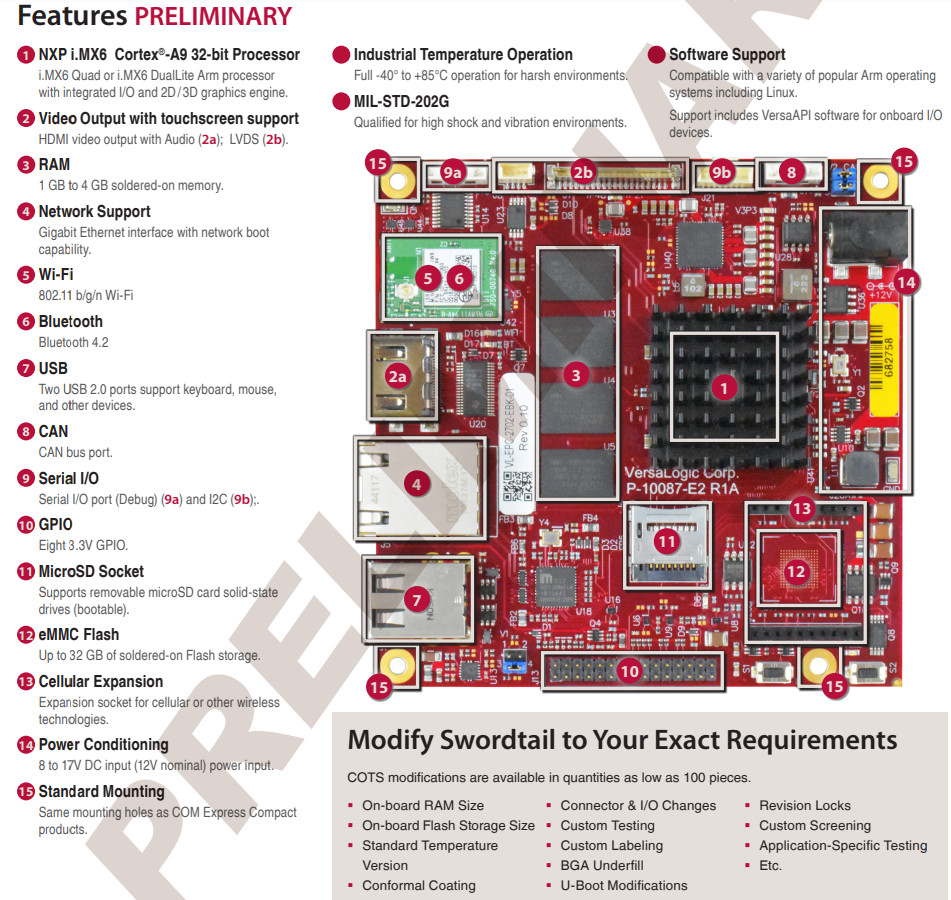
Processor — NXP i.MX6 Quad or DualLite (4x or 2x Cortex-A9 cores @ up to 800MHz); Vivante GC2000 GPU
Memory/storage:
1GB (DualLite) or 2GB (Quad) DDR3L SDRAM soldered, with up to 4GB optional
MicroSD slot (bootable) with optional 8GB card containing Linux
eMMC (MLC) socket with up to 32GB optional bootable storage
Wireless:
Single-band 802.11b/g/n and Bluetooth 4.2
NimbleLink Skywire socket (20-pin) for cellular and other wireless expansion
Optional antennas
Networking — Gigabit Ethernet port with network boot, latching connector
Media I/O:
HDMI v1.4 port with audio
24-bit LVDS for up to 1366 x 768 with backlight and I2C touch (with interrupt input)
Other I/O:
2x USB 2.0 host ports
CAN 2.0B
RS-232 debug
8x GPIO/DIO (3.3V)
I2C
Up to 3x PWM (reduces GPIO lanes)
Other features — 6-axis accelerometer/magnetometer; 10-year lifecycle support; optional cables
Operating temperature — -40 to 85°C with 0.5 linear meters per second airflow
Power — 8-17 VDC input (12V nominal); consumption: 2.2W idle,; 2.7W (DualLite) or 3W (Quad) typical operating
Dimensions — 95 x 95 x 21.4mm; compatible with COM Express Compact footprint and mounting holes
Weight — 68 g
Operating system — bootable Yocto 2.1 Linux OS; compatible with other-friendly OSes
Like all VersaLogic products, the Swordtail SBC is engineered and tested to be rugged. It is fully validated for operation in unforgiving environments where extreme temperatures and mechanical shock and vibration occur. Each component has been carefully sourced, and the design optimized and validated, to ensure reliable operation in the field.
Swordtail embedded computer boards provide connectivity via Wi-Fi, Bluetooth, Gigabit Ethernet, USB, and CAN bus interfaces, as well as HDMI video and audio support and LVDS panel support with backlight and touchscreen signals. Additional on-board I/O includes I2C with interrupt input support, and GPIO lines.
The Swordtail will be available in Q2 from VersaLogic and Digi-Key, with OEM pricing starting at $239. More information may be found in Versalogic’s Swordtail announcement and product page.
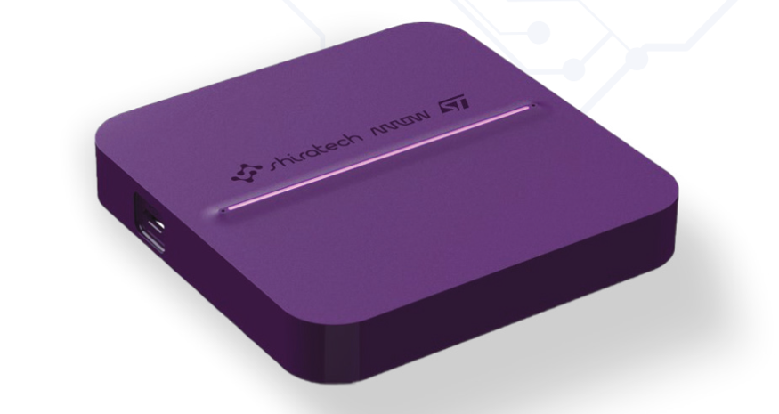
Shiratech Solutions has launched the IoT Cube Box, an IoT gateway that offers direct and easy connection to the cloud. IoT Cube Box uses the newly launched STM32MP1 series MPU from ST. It is designed for use in smart home, smart city and white goods applications. The device runs at up to 650MHz, using a high-performance Arm Cortex-M4 microcontroller core running at 209MHz. It features:
Build in LTE & WIFI connectivity
Based on STM32MP157 MPU
Operating system – Linux (Linaro Debian)
Main Features
CPU – STM32MP157 MPU
LTE – Quectel BG96
WIFI/BT – Murata LBEE5KL1DX RF TXRX MOD
BLUETOOTH/WIFI
Gas sensor – CCS811 – (By AMS) – Ultra-Low Power Digital Gas Sensor for Monitoring Indoor Air Quality
2 X Microphones IM69D130 (Infineon)
High performance digital
XENSIVTM MEMS microphone
Build in chargeable battery Li-Iion 1AH
1 x USB OTG interface (For charging and communication)
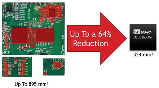
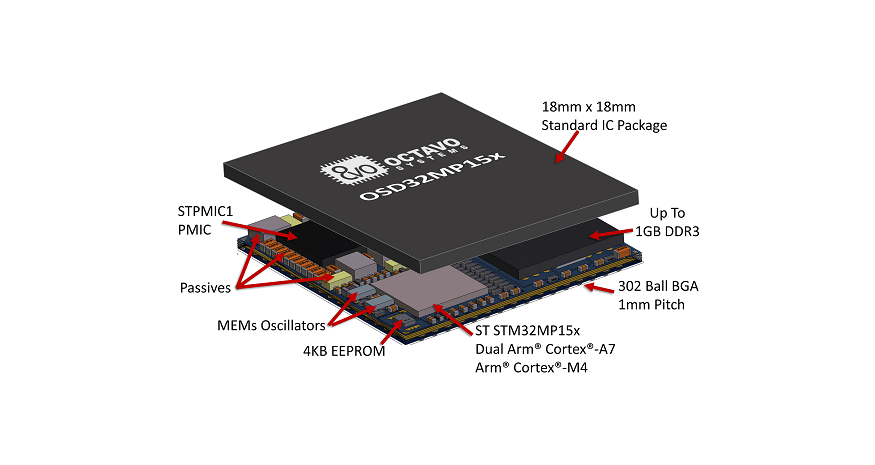
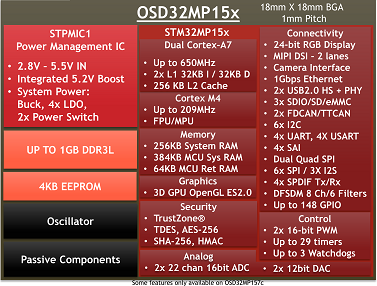
Embedded World, Nuremberg, Germany (February 25, 2019) – Octavo Systems today introduced the OSD32MP1, their first System-in-Package (SiP) product based on the new STM32MP1 microprocessor from STMicroelectronics. The OSD32MP1 allows users of the popular STM32 family to move to Linux without adding size or complexity to their design. Octavo has leveraged their years of experience creating tightly integrated system building blocks to develop a device that is up to 64% smaller than an equivalent system made from discrete components. At only 18mm X 18mm the OSD32MP1 is the same size as the STM32MP1 but integrates:
STMicroelectronics STM32MP1 microprocessor
STPMIC1 Power Management IC (PMIC)
Up to 1GB of DDR3 memory
4K non-volatile EEPROM
MEMs oscillators
Over 100 passives
All into a single BGA package
The new STM32MP1 contains Dual Arm® Cortex®-A7 microprocessors along with an Arm® Cortex®-M4 microcontroller. It has a wide range of peripherals spanning from two 22 Channel ADCs, to a camera interface, to 1Gbps ethernet, to a 3D GPU, making it a great fit for remote sensors, HMI displays, motor control applications, medical systems, and IoT end points. The integration provided by the OSD32MP1 SiP makes the solution ideal for any application needing a versatile applications processor in a small package.
Design resources for the OSD32MP1 are available today on the Octavo Systems website. Samples will be available in Q3 with full production scheduled for Q4.
Pricing is still being finalized and will be in-line with the cost of an equivalent system designed with discrete components,
Ever since the first microcontroller was released in 1980 by Intel – the Harvard Architecture 8051 mcu – microcontrollers have revolutionized the electronics industry and has spurred an array of low-cost microcontrollers like PIC, AVR, ARM, and others. The AVR has been the one that found love within the maker’s ecosystem, thanks to the introduction of Arduino, and over the years, there has been a heated debate between AVRs and PIC – which one is better? Well, I think both compliments themselves, although I have always preferred AVR chips though.
Recently, on my quest for some randomness, I stumbled upon a set of Microchip PIC microcontrollers tools from iCircuit Technologies which seems to enhance the already known development tools for working with PIC microcontrollers. When programming PIC controllers, traditional development tools like PICKit 2, PICKit 3, MPLAB IDE have been the de-facto standard, and tools offered by iCircuit seems to bring some new interesting perspective to your normal PIC development cycle.
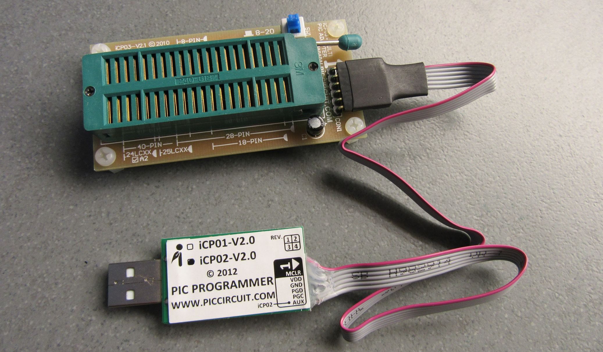
iCP02 – USB Microchip PIC Programmer
iCP02 – USB Microchip PIC Programmer + iCP03 – Multi PIC Adapter
Similar to the PicKit 2, the iCP02 is a USB Microchip PIC Programmer for programming your chips. It’s ICSP (In-Circuit Serial Programming) based, and requires five connections between the programmer and the adapter or microcontroller.
iCP02 USB Microchip PIC Programmer can be used for programming up to 260+ type of popular Flash PIC MCU, includes PIC10F, PIC12F, PIC16F, PIC18F, PIC24F, dsPIC30 and dsPIC33 family, serial EEPROM 11LCXX, 24LCXX, 25LCXX, 93LCXX and KEELOQ HCSXX and is also compatible with Microchip’s PICkit 2, MPLAB IDE and MPLAB X.
The toolset consists of a programmer plus an adapter and it offers a level of performance and scalability for PIC programmer solution. It supports all major operating systems: Windows XP, Windows Vista, Windows 7, Windows 8, Windows 10, Linux and Mac OS X and it allows users to program their hex code into the well-known Flash PIC MCUs and EEPROMs by using a simple USB connection.
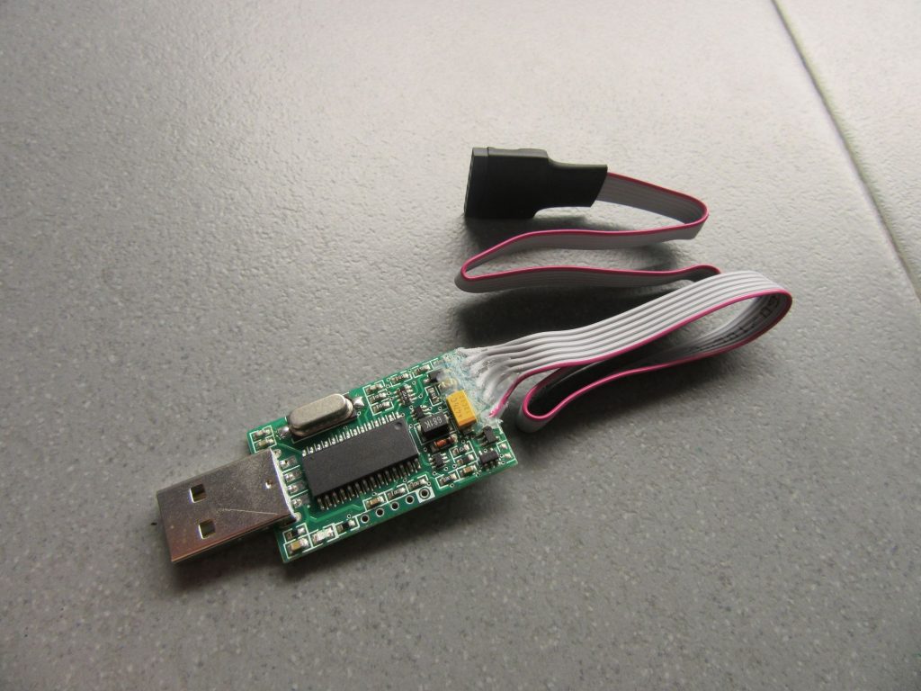
iCP02 – USB Microchip PIC Programmer
Specifications
Used for programming up to 260+ (with PICkit2) or 900+ (with PICkit2 Plus) types of popular Flash PIC MCUs, that includes PIC10F, PIC12F, PIC16F, PIC18F, PIC24F, dsPIC30 and dsPIC33 family.
All major operating systems supported
USB Plug and Play
UART Mode
Full-Speed USB & High Voltage Programming
Low cost and portable size
Compatible with Microchip’s PICkit 2, MPLAB IDE and MPLAB X
The device is available for purchase for $20.90 on piccircuit.com. More information about the Programmer is available on the product page.
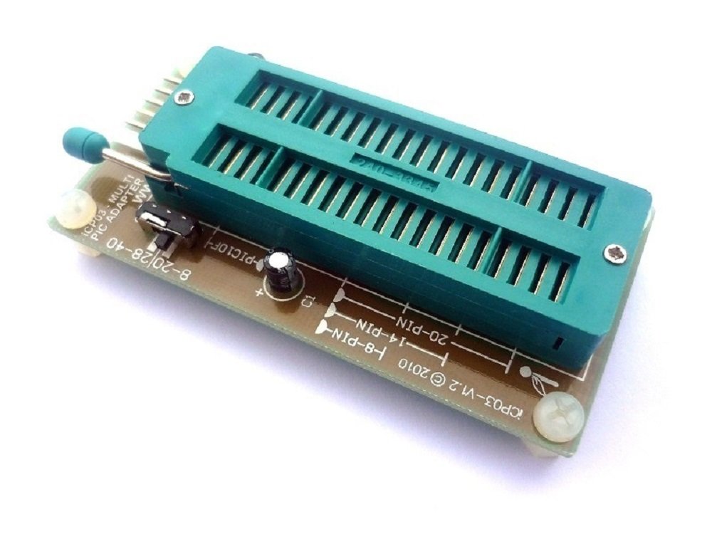
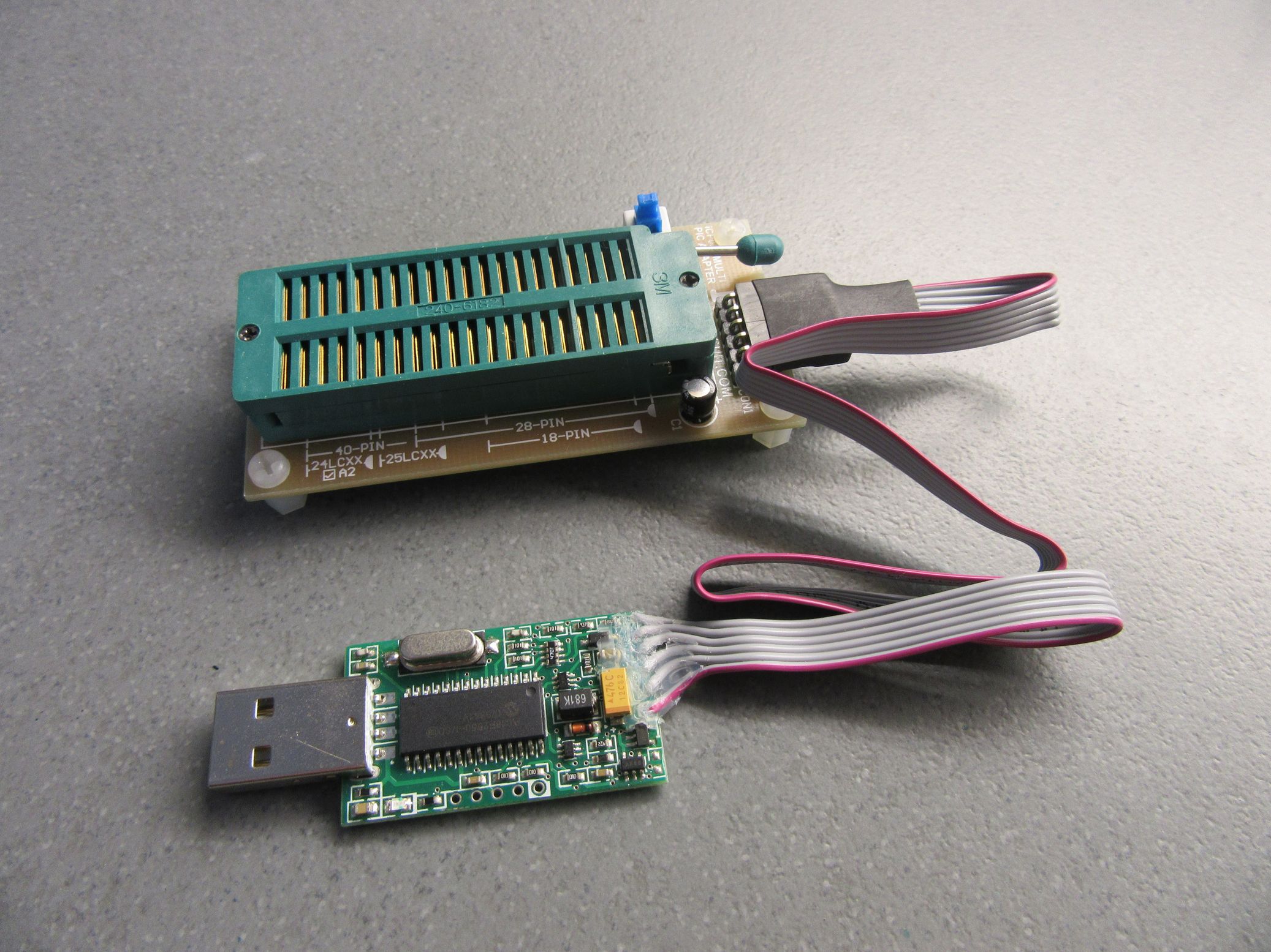
iCP03 – Multi PIC Adapter
iCP03 – Multi PIC Adapter
A PIC programming adapter is one of the first arsenals of tools you need in programming your chip which doesn’t work alone, but will require connecting to a suitable programmer like iCP02. The iCP03 – Programming adapter is a multi PIC adapter which can support a variety of PIC chips. It offers off-board programming with a wide range of supported PIC microcontrollers which are available 8 to 40 pin DIP packages.
The adapter provides support for the PIC10F, PIC12F, PIC16F, and PIC18F (J-series and, K-series) family by using single ZIF socket. The iCP03 – Multi PIC Adapter is available for purchase for $12.90 on piccircuit.com.
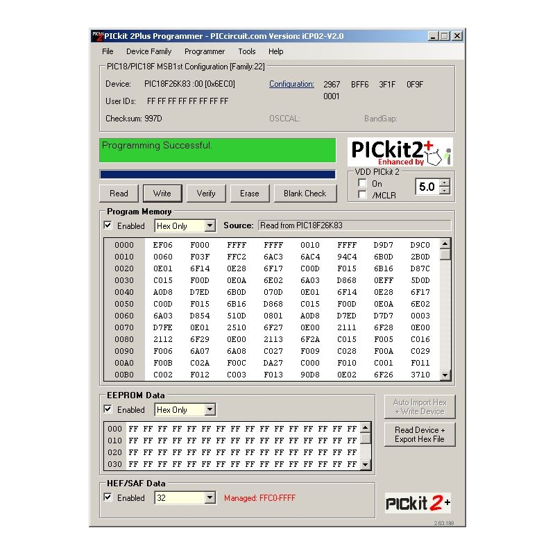
PICkit2 Plus (Enhanced PICkit2 Version)
PICkit2 Plus (Enhanced PICkit2 Version)
The programming software comes in 3 variants: GUI Software (Only), Command Line (Only), and GUI Plus Command Line. The PICKit2 Plus is a replacement programming tool for the existing Microchip PICKit2 software. Unlike the original software, the Plus supports the latest Microchip PICs, dsPIC, PIC24, PIC32, MCP, EEPROM, KEELOQ family with a new programming protocol, improved Windows support, HEF/SAF memory feature, and improved usability.
The software supports a vast set of controllers for over 900+ flash PIC MCUs and you can also manage SAF and HEF memory.
Specifications
Programming CAN I/O Expander & KEELOQ series: MCP2502X/5X & HCSxx
Read and write operation for serial EEPROM 11LCxx, 24LCxx, 25LCxx and 93LCxx.
Supports Windows-based OS
An improved user interface, help, guidance and direct access to the 8-bit Microchips PIC microcontroller database.
USB (Full speed 12 Mbits/s interface to host PC)
Low voltage to 2.0 volts (2.0v to 5.0v range) for iCP02 supported.
Erase of program memory space with verification.
and many more.
Is it available for free? No, at least not yet. The software is available for download for $11.90 at piccircuit.com but the GUI and Command line version will set you back an extra $10.6 totaling $22.50 and it is available for purchase online.
The above mentioned software and hardware tools by iCircuit Technologies provide a complete toolset for engineers and makers working with PIC microcontrollers. More information about the PIC tools is available on the product listing page.
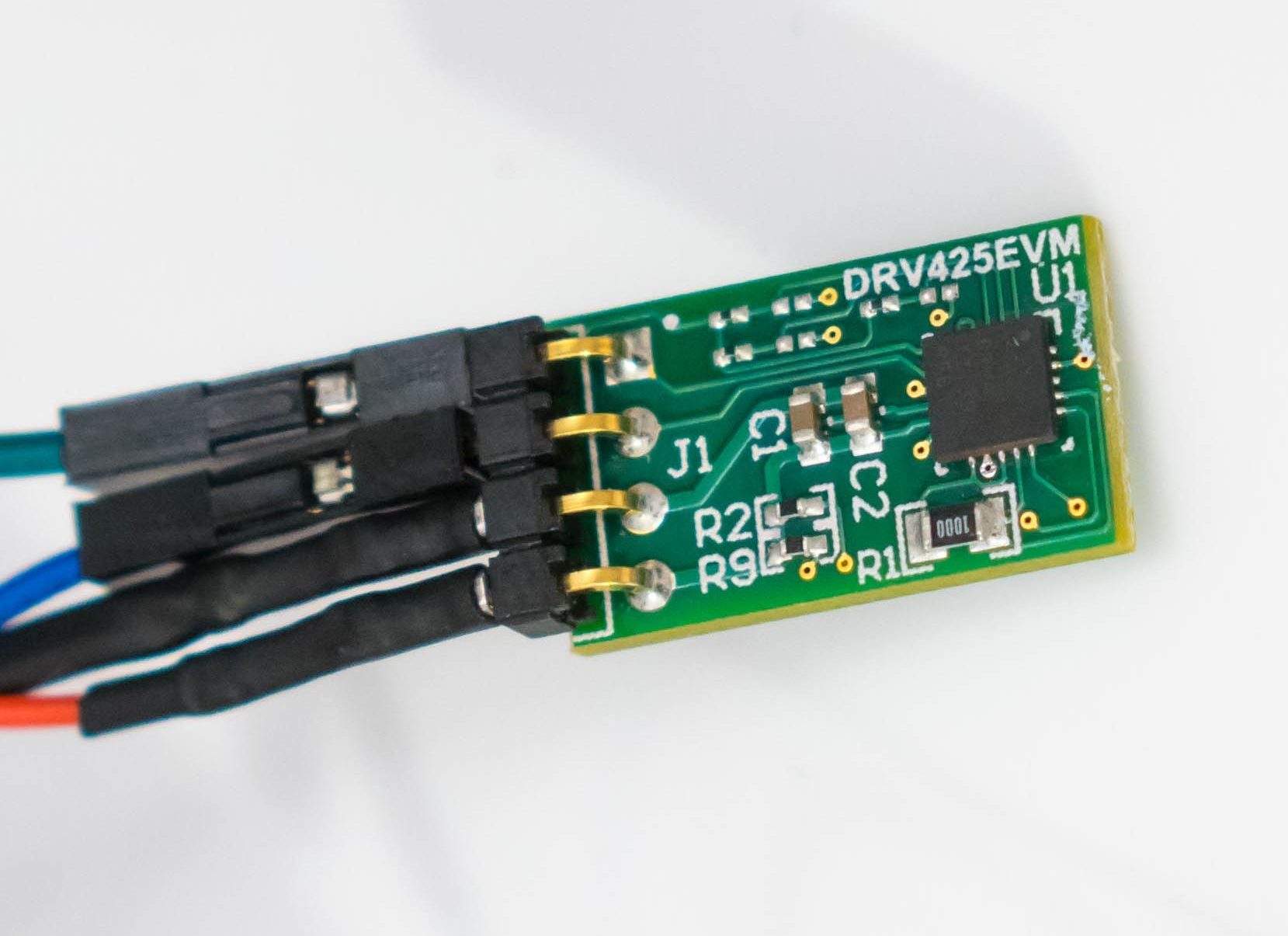
shabaz @ element14.com show us how to build a Current Probe based on DRV425 Integrated Fluxgate Magnetic Sensor IC. He writes:
Current measurement can be really awkward when working with circuits. Voltage measurements are (usually) straightforward, but when it comes to current measurements the story is different. One typical approach is to insert a known resistance by breaking the circuit, and then measuring the voltage across it. This is difficult if one end of the resistor is not at ground potential, because oscilloscope probes are (usually) designed with the ground leads all connected together, and it will damage things if the grounds of different channels on the oscilloscope are connected to different parts of the circuit.
This project describes a very sensitive home-made current probe that doesn’t require a known resistance to be inserted. It has not been fully characterized but the initial results are reasonably promising. It was tested at currents of the order of single-digit microamps up to 10mA (it can be assembled for higher current ranges if desired), and it functions from DC to around 20kHz, and is fully isolated.
A DIY Fluxgate Magnetometer based Current Probe – [Link]
Usually, everyone switches “OFF” all electrical appliances in their home, including Air conditioners when leaving the house, this means when you get back home, the temperature will not be regulated, and it will take the air conditioner some time to achieve your desired level of coolness. But what if you could automatically control your air conditioner from your mobile phone when you are a few blocks away from home? What if you could turn it OFF from wherever you are, if you discover you left it ON when leaving the house? What if it can be synced with your phone’s location and turned ON when you are almost home? What if it can be synced with the weather information of your phone? These and many more questions, inspired today’s project.
ESP8266 WiFi Air Conditioner Remote Control – [Link]
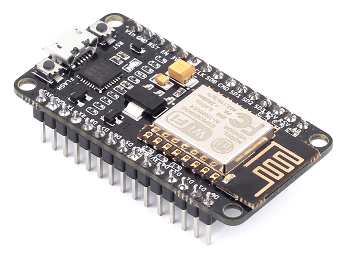
We recently started exploring the ESP8266 boards and today’s project is going to be an interesting one based on this WiFi module. We are going to build an ESP8266 based WiFi Air condition Remote Controller. While this project can be adapted to fit any device that uses a remote control, we will use it for controlling an Air Conditioner.
Usually, everyone switches “OFF” all electrical appliances in their home, including Air conditioners when leaving the house, this means when you get back home, the temperature will not be regulated, and it will take the air conditioner some time to achieve your desired level of coolness. But what if you could automatically control your air conditioner from your mobile phone when you are a few blocks away from home? What if you could turn it OFF from wherever you are, if you discover you left it ON when leaving the house? What if it can be synced with your phone’s location and turned ON when you are almost home? What if it can be synced with the weather information of your phone? These and many more questions, inspired today’s project.
ESP8266 based WiFi remote controller.
How it works
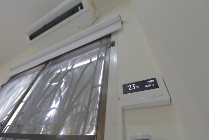
The air conditioner (AC), is normally controlled by a “remote control” which sends infrared signals to it when a button is pressed. The AC interprets the signals and converts them to instructions to either increase its coolness or reduce it, go OFF or come ON, etc. Thus to be able to control it using our own device, the device will have to be able to mimic and send the same signals sent by the remote to the AC, such that, by pressing the “ON” button (as an example) on the app, our WiFi remote control sends the same IR signal the remote would have sent if the “ON” button was pressed.
The device we are going to build is based on the ESP8266 and it’s wonderful features and use has been discussed in one of our past tutorials. The ESP8266 will be connected via MQTT to home bridge and through it, Siri can be used to give instructions to control the AC. Once the instruction (say “turn on” for instance) is received over MQTT, the NodeMCU matches it with corresponding IR signals and the signal is sent to the AC through an IR led. An OLED display is used to provide visual feedback about the current state to the user. For non-iPhone users, the device can also be connected to the Amazon Alexa.
Asides the control of the Air conditioner via Siri or Apple’s home kit, it is also equipped with control switches.
To make the experience a complete one, the following features were added to the project;
Display NTP Clock when standby.
Simple button control. Power, Temp up / down.
Can control temperature, swing, fan speed and mode with HomeKit.
Auto brightness according to ambient light.
OTA Firmware upgrade.
Control via HomeKit using HeaterCooler Service (iOS 11+)
Works with Amazon Alexa using fan service
At the end of today’s tutorial, you would know the basics of building IoT solutions and Home automation. You would also learn how to intercept signals sent by IR based remote controls, ( please do this within lawful limits and do not apply to dangerous situations), create an IR transmitter which could be used to control all IR remotes based appliances in your home or office, and build devices that can be controlled via Apple’s Home kit.
Required Components
The following components are needed for this tutorial;
The LDR is not compulsory as it was used to dim or turn off the backlight and make the OLED screen easier to read.
Schematics
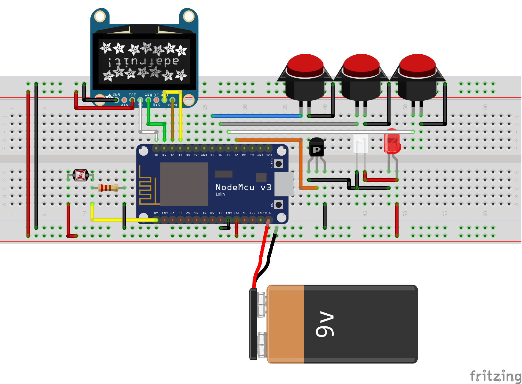
As mentioned in the project description, the hardware part of the project itself is made up of the NodeMCU, an IR LED, some push-buttons and an OLED Display.
Connect the components as shown in the schematics below.
Schematics
The push-buttons provide an alternative way of controlling the device when you are not carrying your mobile phone, and the OLED display provides diverse information including the current temperature being maintained by the AC.
Another view of the schematics is provided below to make it easier to follow.
Preparing the System
Before we write the code for the project, we need to make some preliminary preparations.
Prepare the IR signals that will be sent to the AC for each command
Setup Communication with Homekit
1. Decoding the IR signals
As mentioned above, this project works by mimicking the IR remote, sending out IR signals generated based on the commands from Homekit. Since the IR signals have to be the same as the one sent by the remote, we need to obtain the IR code for each button before anything else. To obtain the codes, we have to build a device which receives the IR signal from the remote control, decodes it and displays the encoded data so we can copy it for use later on.
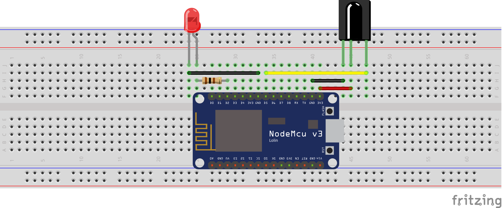
To obtain the IR codes, we will use the cheap, efficient and popular TSOP1738IR receiver, connected to Nodemcu, in the way that when a button on the remote is pressed, the IR receiver will pick it and through the decode sketch running on the NodeMCU, it will print the content of the signal on the serial monitor. This content will be later used to control the AC.
Schematics
Connect the IR receiver to the NodeMCU as shown in the image below:
To determine when an IR signal is received and help us for debug, a LED was added in the schematics so that it only comes on when an IR signal is received.
Here is a pin map of the connection between the NodeMCU and the TSOP;
Today’s project is heavily dependent on the IRremote ESP8266 library, which can be downloaded from the link attached. The library is based on the standard Arduino IRremote library and comes with the decoded data (for few common keys), for quite a number of popular remote controls, which means that you could be lucky, and the codes for your remote will be already available in the library. For those that are not so lucky, along with the schematics above, we will use the example sketch, IRrecvDumpV2 which comes with the IRremote ESP8266 library to obtain the codes.
With the library installed, launch the Arduino IDE, go to examples and select the IRrecvDumpV2 example. Upload the code to your NodeMcu and press a button on your remote control. You should see an array of numbers show up in the serial monitor every time a button on the remote is pressed. Copy and keep the array for each key as they represent the decoded IR signals sent by the remote and we will use them to reproduce the IR signal for our Air conditioner. The code is well commented and should be easy to follow.
2. Connecting with Homekit
The second thing we need to do before writing the code is setting up the connection to Homekit. Connection to Homekit gives us the ability to control the device using Siri and the Homekit app. To achieve this, we will use the Homebridge-MQTT installed on a RaspberryPi which will serve as our server. The Homebridg-MQTT is essentially a plugin for homebridge that allows you to add and control devices via the MQTT protocol.
Boot up your RaspberryPi and open a terminal. We will start by updating the Pi to ensure we don’t run into any compatibility issue later on.
Run:
Sudo apt-get update
with this done, Install MOSQUITTO on the pi for MQTT. run;
sudo apt-get install mosquitto
once this is done, install the Homebridge-MQTT plugin using;
sudo npm install -g homebridge-mqtt
Next, we need to edit the config file. the config file is located inside the homebridge folder (home / .homebridge /config.js). Change into the directory and run;
sudo nano config.js
Add the platform section to the config file such that it now looks like this;
Run HomeBridge, use MQTT LENS (can be downloaded from Chrome Webstore) and add Connection to our Raspberry Pi, creating an accessory that uses the heater-cooler service which is supported by any version of the IoS from IOS11. Set the publish to value as;
With all these done, we can now proceed to write the code for this project.
Code
The code for today’s project will be developed using VScode and the platform.io IDE plugin. The code is quite bulky and may be difficult to follow for anyone not used to programming microcontrollers using these tools so we wrote a simple tutorial on using these tools, be sure to check it out.
As mentioned earlier, the code for today’s project is heavily reliant on the IRremoteESP8266 library, but it also utilizes the Wifi manager library, the Arduinojson library, the Arduino OTA library, and the NTP library. Each of these libraries made it easy to achieve different parts of the project. The IRremoteESP8266 library was used to send IR signals from the device to the Air conditioner, the Wifimanager library was used to make it easy to change the WiFi credentials, the Arduinojson was used to parse the data from homekit and the Arduino OTA library was used to enable over the air firmware update on the device. Other libraries used include U8g2 library which makes it easy to work with monochrome displays. It was used to display the graphics which formed the UI for the project. All the libraries used for this project can be downloaded and installed via the Arduino library manager.
The code for this project is quite bulky and may be too much to explain here but we have ensured it is well commented and attached in the zip file under the download section. The zip file contains a bunch of files including the graphics images used for the GUI, the libraries, and everything about the project. The code is located in the “src” folder. The “src folder also contain different codes most of which are header files for the main code-named main.cpp. All other files are important and need to be in the same project folder as the main.cpp as they contain all the information needed by the main file. For instance, main.h file, contains the MQTT declarations among other things while the UI.h file contains the char values of everything used for the UI.
For those who may be interested in creating their own UI for the project, check out this tutorial we created a while back. It might give you the necessary start point.
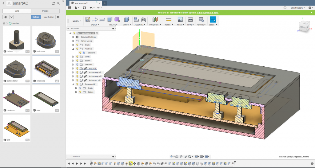
Enclosure
To make the project look pleasing to the eye, an enclosure was 3D printed. The design was done using Fusion 360 and all the design files are included n the zip file under the download section.
Enclosure Design with Fusion 360
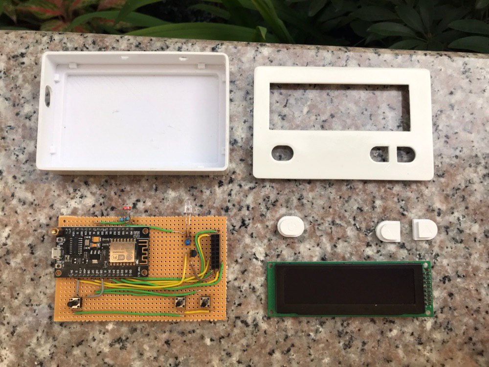
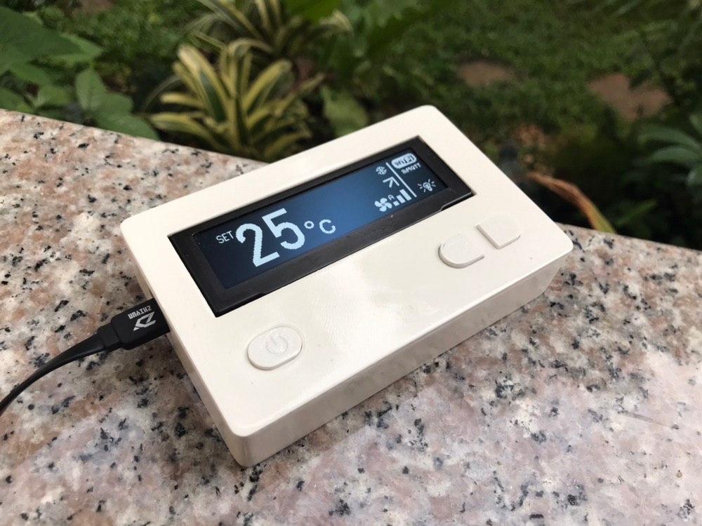
After printing, the enclosure was scrubbed and painted to make the print look better. The final enclosure is shown in the image below.
Demo
Ensure that the connections are as described and switch on your device. It should come up as shown in the picture below.
That’s it for this tutorial guys. As said in the beginning, the applications for this project are limitless. It can serve as a simple box that controls every IR remote controlled device in your house. Do let me know if you have questions and what cool ideas you will be implementing with all you have learned here.
Till next time.
A video of the device in action can be seen below:
Variscite reveals the portfolio of its new i.MX based products that will be presented next week at the Embedded World 2019 exhibition & conference. Variscite is the only NXP partner who was granted early access to all i.MX 8 programs and will present next week a respectable number of new System-on-Modules based on i.MX 8M Mini, i.MX 8QM and i.MX 8X as well as the i.MX 8M that was released in 2018.
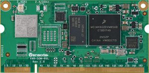
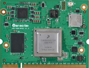
Alongside the i.MX 8 platforms, the company will also showcase the VAR-SOM-6UL, its new member to the ‘VAR-SOM pin2pin family’ based on NXP i.MX 6UltraLite / 6ULL / 6ULZ processors.
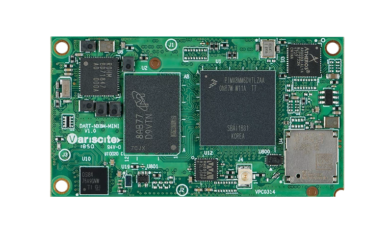
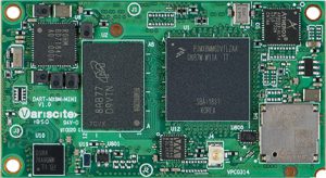
The official launch of the DART-MX8M-MINI
The DART-MX8M-MINI System-on-Module (SoM) will be officially launched at the upcoming Embedded World exhibition. The DART-MX8M-MINI is a miniature SoM based on NXP’s i.MX 8M Mini processor with up to 2GHz Quad-core ARM Cortex-A53 plus 400MHz Cortex-M4 real-time processor. The SoM offers integrated HW engines supporting 1080p video encode and decode, 2D and 3D graphics, HQ audio and a wide range of connectivity options such as Wi-Fi/BT, Ethernet, and USB.
The DART-MX8M-MINI joins Variscite’s ‘DART Pin2Pin Family’ and provides a pin2pin scalable option to Variscite’s DART-MX8M with lower power consumption and higher CPU performance. Later this year the company is expected to launch the DART-MX8M-NANO based on the upcoming NXP i.MX 8M Nano processor for further cost/performance scalability of the ‘DART Pin2Pin Family’.
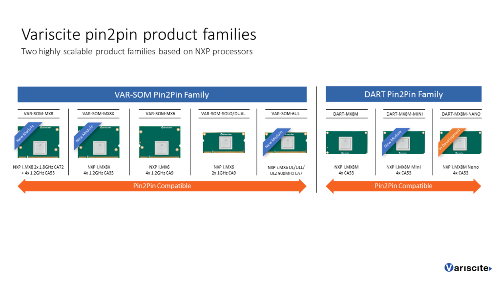
The VAR-SOM Pin2Pin Family
The company is expanding its ‘VAR-SOM Pin2Pin product Family’ with several new products which will be presented at the Embedded World exhibition: The VAR-SOM-MX8, VAR-SOM-MX8X and VAR-SOM-6UL. The Pin2Pin family offers Variscite’s customers a high level of scalability, extended lifetime availability and reduced development time, cost and risk.
Variscite’s new products highlights
VAR-SOM-6UL
Availability: Evaluation kits and samples are available for order.
Based on NXP i.MX 6UltraLite / 6ULL / 6ULZ ARM Cortex-A7 processor with up to 900MHz CPU Clock. The SoM highly integrated connectivity includes a certified dual-band Wi-Fi 802.11ac/a/b/g/n, Bluetooth/BLE, dual Ethernet, dual USB, audio, camera in, 24bits Parallel LCD / 18bits LVDS display up to WXGA and serial interfaces.
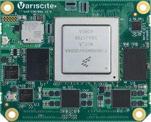
DART-MX8M-MINI
Availability: Evaluation kits and samples are available for order.
Based on NXP i.MX 8M Mini processor with up to 2GHz Quad-core ARM Cortex-A53 plus 400MHz Cortex-M4 real-time processor. The SoM offers integrated HW engines supporting 1080p video encode and decode, 2D and 3D graphics, HQ audio and a wide range of connectivity options such as Wi-Fi/BT, Ethernet, and USB.
VAR-SOM-MX8X
Availability: Evaluation kits and samples are available for order.
Based on NXP i.MX 8QuadXPlus / 8DualXPlus / 8DualX processors with up to 4 1.2GHz Cortex-A35 cores. The SoM provides efficient power/performance architecture, built-in safety features and highly integrated multimedia support.
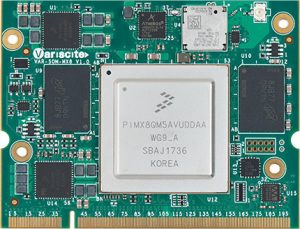
VAR-SOM-MX8
Availability: Early partner access for evaluation kits; Official launch is expected in Q2 2019.
Based on NXP i.MX 8QuadMax with Dual 1.8GHz ARM Cortex-A72, Quad 1.2GHz Cortex-A53 and 2x 266MHz real-time Cortex-M4F co-processor. The VAR-SOM-MX8 introduces advanced processing power, high-end graphics, UltraHD video capabilities and a variety of high-speed interfaces and connectivity options.
SPEAR-MX8
Availability: Early partner access for evaluation kits; Official launch is expected in Q2 2019.
Based on NXP i.MX 8QuadMax with Dual 1.8GHz ARM Cortex-A72, Quad 1.2GHz Cortex-A53 and 2x 266MHz Real-time Cortex-M4F co-processor. An ideal solution for embedded products requiring advanced performance processing, high-end graphics, UltraHD video capabilities and a variety of high-speed interfaces and connectivity options.
All demos can be found on hall 4A / 4A-340 at the Embedded World exhibition.
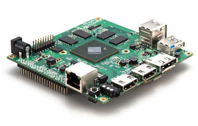
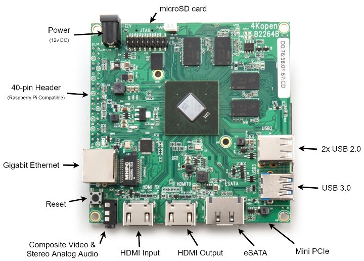
4Kopen has showcased at 2019 Integrated Systems Europe (ISE 2019) at the beginning of the month a new 4K capable board featuring STMicro STiH418 Media Processor. The development board comes with 2 GB RAM, HDMI 2.0 output, HDMI 1.4 input, Gigabit Ethernet, USB 3.0, a mini PCIe slot fitted with an 802.11b/g/n WiFi module, an eSATA connector and more.
The board is a fully open source 4K development platform with OrCAD and PDF schematics, Gerber files, and datasheet all available for download. There’s also a Wiki explaining how to get started with Raspbian or buildroot built Starkl Linux distributions, and how to use the GStreamer media APIs
Output – HDMI 2.0 Tx up to 2160p60, 3.5mm AV jack with composite video and stereo audio
Input – HDMI 1.4 Rx up to 2160p30
Video Decode/Encode
Ultra HD Decoding, up to 2160p60
Full HD Encoding, up to 1080p60
Networking – Gigabit Ethernet, 802.11b/g/n WiFi 4
USB – 1x USB 3.0 port, 2x USB 2.0 ports
Expansion
Mini PCIe slot (wireless module included)
40-pin GPIO header
Debugging – JTAG header
Misc – Reset button
Power Supply – 12V DC
Dimensions – TBC
You can purchase a board for £150 on Amazon UK or larger quantities on the 4kOpen website. Alternatively, you could try your luck via an Electronics Weekly contest where they will offer 10 boards for free to randomly selected contestants by the 31st of March.
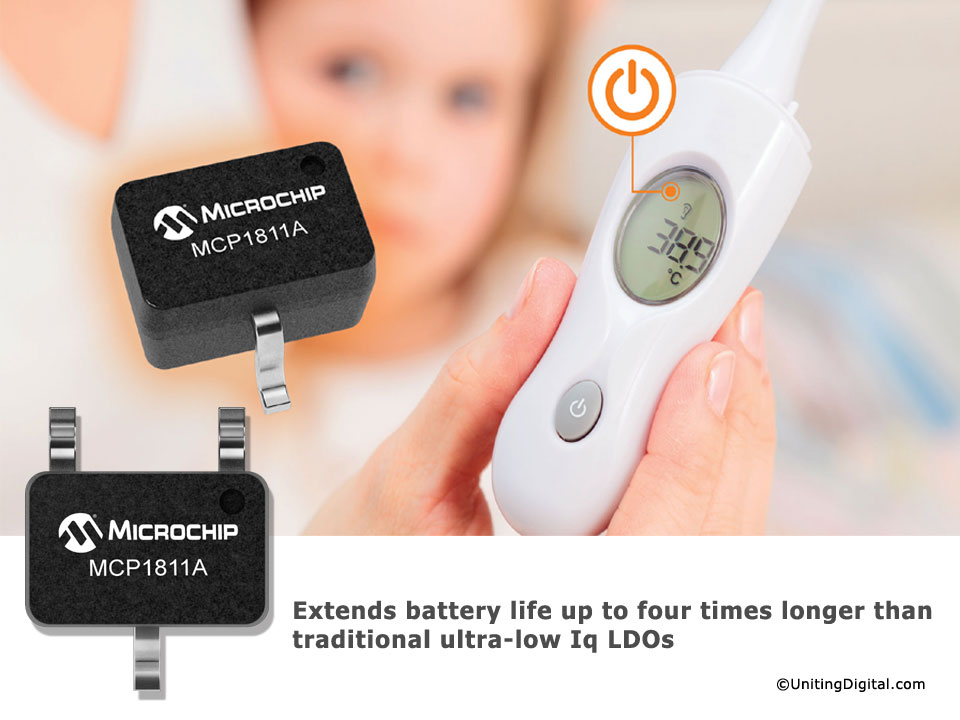
With ultra-low quiescent current of 250 nA, the MCP1811 enables battery life which is four-times longer than conventional ultra-low Iq LDO regulators. Compact packages down to 1 x 1 mm also help the MCP1811 to minimise board space.
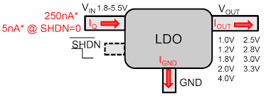
The MCP1811/12 devices are 150 mA (MCP1811) and 300 mA (MCP1812) low dropout (LDO) linear regulators that provide high-current and low-output voltages while maintaining an ultra-low 250 nA of quiescent current during device operation. In addition, the MCP1811B/12B can be shut down for 5 nA (typical) supply current draw.
The MCP1811/12 family comes in nine standard fixed output-voltage versions: 1V, 1.2V, 1.8V, 2.0V, 2.5V, 2.8V, 3.0V, 3.3V, and 4.0V. The 150/300 mA output current capability, combined with the low output-voltage capability, make the MCP1811/12 device family a good choice for new ultra-long-life LDO applications that have high-current demands, but require ultra-low power consumption during sleep periods.
The MCP1811/12 is stable with ceramic output capacitors that inherently provide lower output noise and reduce the size and cost of the entire regulator solution. Only 1 μF (2.2 μF for MCP1812) of output capacitance is needed to assure the stability of the system with a low noise output.
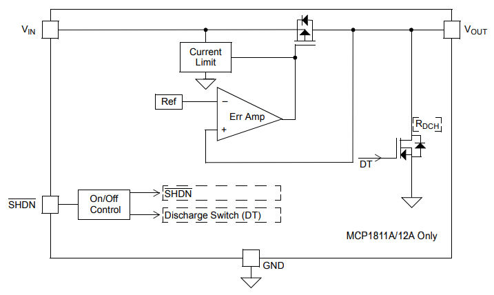
Block Diagram
Additional Features
Ultra-Low Quiescent Current: 250 nA (typical)
Ultra-Low Shutdown Supply Current: 10 nA typ (MCP1811A) and 5 nA typ (MCP1811B)
Input Voltage Range: 1.8V to 5.5V
Standard Output Voltages: 1.0V, 1.2V, 1.8V, 2.0V, 2.5V, 2.8V, 3.0V, 3.3V and 4.0V
Low Dropout Voltage: 400 mV (typical) w/ Small Variation Over Load Range
Stable with Ceramic Output Capacitor: 1.0 uF
Overcurrent Protection w/ Foldback
Output Discharge (MCP1811A)
Available in 3 and 5 lead SOT-23, 3 and 5 lead SC70, 4 lead 1x1mm UDFN
The MCP1811/12 can be paired with other ultra-low current devices, such as Microchip’s nanoWatt eXtreme Low Power (XLP) technology devices, for a complete ultra-low-power solution.