Texas Instruments LMR14010A Step-Down Converters

Texas Instruments LMR14010A Step-Down Converters are the Pulse Width Modulation (PWM) DC-to-DC buck regulators with a wide input voltage ranging from 4V to 40V. These converters operate at a fixed frequency of 0.7MHz, allowing the use of small external components while minimizing output ripple voltage. The device has built-in protection features such as pulse-by-pulse current limit, thermal sensing, and shutdown due to excessive power dissipation. The LMR14010A step-down converters feature soft-start, low dropout operation, and ultra-high efficiency at light load with Eco-mode™. Typical applications include smart meters, appliances, elevators, escalators, and cameras.

The LMR14010A step-down converters are optimized for up to 1A load current and 0.765V nominal feedback voltage. The custom design can be created using the LMR14010A regulators with the WEBENCH® power designer. The LMR14010A converters are available in a low-profile TSOT-6L package with 2.9mm x 1.6mm x 0.85mm dimension. These converters are more suitable for a wide range of applications from industrial to automotive.

Block Diagram

Features

  • 4V to 40V input voltage range with a transient protection to 45V
  • 0.7MHz switching frequency
  • Ultra-high efficiency at light load with Ecomode™
  • Low dropout operation
  • Output current up to 1A
  • Precision enable input
  • Overcurrent protection
  • Internal compensation
  • Internal soft-start
  • Small overall solution size (TSOT-6L package)

more information: http://www.ti.com/product/LMR14010A

Converting Wi-Fi signals to electricity with new 2-D materials

battery-free “rectenna” – image by Christine Daniloff

Device made from flexible, inexpensive materials could power large-area electronics, wearables, medical devices, and more. by Rob Matheson | MIT News Office

Imagine a world where smartphones, laptops, wearables, and other electronics are powered without batteries. Researchers from MIT and elsewhere have taken a step in that direction, with the first fully flexible device that can convert energy from Wi-Fi signals into electricity that could power electronics.

Devices that convert AC electromagnetic waves into DC electricity are known as “rectennas.” The researchers demonstrate a new kind of rectenna, described in a study appearing in Nature today, that uses a flexible radio-frequency (RF) antenna that captures electromagnetic waves — including those carrying Wi-Fi — as AC waveforms.

The antenna is then connected to a novel device made out of a two-dimensional semiconductor just a few atoms thick. The AC signal travels into the semiconductor, which converts it into a DC voltage that could be used to power electronic circuits or recharge batteries.

In this way, the battery-free device passively captures and transforms ubiquitous Wi-Fi signals into useful DC power. Moreover, the device is flexible and can be fabricated in a roll-to-roll process to cover very large areas.

What if we could develop electronic systems that we wrap around a bridge or cover an entire highway, or the walls of our office and bring electronic intelligence to everything around us? How do you provide energy for those electronics?” says paper co-author Tomás Palacios, a professor in the Department of Electrical Engineering and Computer Science and director of the MIT/MTL Center for Graphene Devices and 2D Systems in the Microsystems Technology Laboratories. “We have come up with a new way to power the electronics systems of the future — by harvesting Wi-Fi energy in a way that’s easily integrated in large areas — to bring intelligence to every object around us.

Promising early applications for the proposed rectenna include powering flexible and wearable electronics, medical devices, and sensors for the “internet of things.” Flexible smartphones, for instance, are a hot new market for major tech firms. In experiments, the researchers’ device can produce about 40 microwatts of power when exposed to the typical power levels of Wi-Fi signals (around 150 microwatts). That’s more than enough power to light up an LED or drive silicon chips.

read more

Voice Control Ready Pico-ITX i.MX8M Board for Embedded IoT Solutions

Estone technology is proud to announce the new addition to our pico-ITX embedded board family – EMB-2238, an NXP i.MX8M based single board computer.  Building upon the success of our i.MX6 board series. The EMB-2238 is our first embedded board to integrated with hardware DSP specially designed for voice control applications, This Quad core ARM Cortex-A53 board takes the advantage of NXP’s latest i.MX8M application processor with up to 15-year longevity, advance audio and 4K video supports.  It is ready for ODM and industrial product designs for the fast-growing edge computing, voice human machine interface (HMI), streaming multimedia, and machine learning applications.

Targeting embedded and IoT applications with voice control, advance audio and display requirements, the EMB-2238 features a PoE (Power over Ethernet) ready GbE port, rich I/O options including RS-232/485 and USB 3.0, over 20 channels of high performance digital audio input and output expansion and dual core hardware DSP for voice-control algorithms. The board also features a 4-lane MIPI DSI and CSI and built in I2C touch panel support for all types of touchscreen applications. A 40-pin expansion header supports PCIe, GPIO, I2C, serial communications and a wide range of expansion options.

EMB-2238 IoT Voice Control Board

The voice control and audio support of the board is where the EMB-2238 truly stands apart. The on-board smart codec provides support for Dual Digital MEMS Microphone inputs, dual-core DSP with multi-mic noise suppression, Automatic Speech Recognition (ASR) enhancement,  acoustic echo cancellation (AEC)  and barge-in technology enable voice commands for during loud music playback., functions. 16 channel digital audio inputs and 10 channel digital audio outputs support microphone array expansion for voice and best in class audio with 32-bit 384KHz at each channel.  BSP supports include Embedded Linux, Android, Qt, Wayland, Amazon AVS (Alexa Voice Service) Device SDK, Sensory TrulyHandsfree Wake Word Engine, and offline Automatic Speech Recognition (ASR), and Natural Language Understanding (NLU) engine, like the Snips AI voice control platform.

EMB-2238 with the Power Over Ethernet module plugged into its 40-pin expansion port

Highlighted Product Specifications

  • Processor – NXP i.MX8M Quad 4x ARM Cortex-A53, AND 1x ARM Cortex-M4
  • Storage – Onboard iNAND flash (8GBdefault), 1x MicroSD Slot, 256k EEPROM
  • Display Options – 1x MIPI 4-Lane DSI for 7”, 8”, 10.1”, and other LCD Panel, 1x MicroHDMI
  • Expansion – 40-Pin Connector with PCIe, GPIO, Front Panel Control, PoE Input, 8-Channel Audio
  • I/O – 1x RS-232/485 Block, 1 x RS-232 Header, 2x USB 2.0 Type A, 2x USB 2.0 Header, 1x USB Type C 3.0 OTG, 4x GPIO, 2x I2C (for TP and MIPI CSI), 1x 4-lane MIPI-CSI
  • Voice Control – Dual Digital MEMS Microphone Header via CS47L24 with Dual DSP, Support Multi-MIC Noise Suppression, Acoustic Echo Cancellation (AEC), Omi-Directional Spatial, 8 Channel Digital Audio/DMIC Inputs (SAI5) for MIC Array

Full Specifications listed for the EMB-2238

  • Processor — NXP i.MX8M (4x Cortex-A53 @ 1.5GHz); Vivante GC7000Lite/GC7000VLX for OpenGL/ES 3.1, OpenGL 3.0, Vulkan, OpenCL 1.2 GPU; Cortex-M4 @ 266MHz
  • Memory/storage:
    • 2GB to 4GB LPDDR4 RAM
    • 8GB iNAND flash
    • MicroSD slot
  • Wireless — 802.11 b/g/n and Bluetooth 4.10 module (USB-based)
  • Networking — GbE port with optional PoE; optional second GbE via PCIe add-on with GPIO, 9-36V input, LED control etc.
  • Display/camera I/O:
    • Micro-HDMI port for up to 4096 x 216 0 @60Hz
    • MIPI-DSI (4-lane) for up to 1920 x 1200 and I2C-based support for LCD touchpanels
    • MIPI-CSI (4-lane)
  • Audio/voice control I/O:
    • Class D 2W mono speaker
    • 2x HP out header
    • 8-channel digital in and out (SAI1) with 32-bit @ 384 kHz fs and TDM support
    • SPDIF, QSPI
    • Cirrus CS47L24 smart codec with 2x-core, 300-MIPS DSP with 3x DAC and audio hub with SoundClear Control
    • 2x digital MEMS mic header (via CS47L24) with multi-mic noise supp., AEC
    • Omni-directional spatial 8 ch. digital audio/DMIC inputs (SAI5) for mic array (via 40-pin)
  • Other I/O:
    • USB 3.0 OTG Type-C port
    • 2x USB 2.0 host ports
    • 2x USB 2.0 headers
    • RS-232/RS-485 terminal block
    • RS232 header
    • 4x+ GPIO, 2x I2C for TP and MIPI CSI
  • Expansion — 40-pin connector with PCIe x1, GPIO, font panel control, PoE, 8 ch. audio in etc.
  • Other features — Watchdog timer; 10 to 15-year support longevity
  • Power — 5V DC header or optional PoE or optional 9-36V input (GbE add-on)
  • Operating temperature — 0 to 60°C
  • Dimensions — 100 x 72mm; Pico-ITX form factor
  • Operating system — Yocto Project (Linux kernel 4.9, Qt, Wayland); Android 8.1.0; ships with Amazon AVS and Sensory TrulyHandsfree Wake Word Engine
EMB-2238 with 10-channel output, 6-channel input audio reference design for high performance sound bar and amplifier

YouTube Video

No pricing or availability information was provided for the EMB-2238 SBC. More information may be found at the Estone Technology EMB-2238 product page.

Live demo of the Snips and Amazon AVS based on Yocto built Linux is available a the Embedded World 2019 at Nuremberg,  Germany,  February 26 – 28.  Both number is Hall1: 1-129.

Novasom M7, M8 & M11 SBCs for Advanced Multimedia Applications

Novasom M11, based on the new Intel Apollo Lake x5, 6th generation of Atom CPU with Microsoft Windows 10 are designed for the typical digital signage applications that require heavy Full HD movies or UHD (4k) to be managed with high fluidity by specific heavy SW or, often, multiple displays.

These boards (with an HW H265 decoder on board) are rugged, practically cold while working, also in extended range temperature, and with a 10 years of availability, because we use only industrial components. Are equipped with our unique dual power input for redundancy and the UPS manager with battery, you can work 24/7 without any problem (a must with Windows based systems).

The market asks also for Android OS and Windows 10 IoT so we developed the Novasom M8 to respond to these “entry level” requirements, even the most severe, we have equipped the M-line entry level with the strongest Designed for Android performing CPU for graphics purposes on the market today (Qualcomm Snapdragon), and defined our SBC to become a small, easily integrated, low level, capable product.

Last but not least there Is the Novasom M7. It’s based on the Rockchip RK3328, a 4X A53 processor. This board can drive UHD (4k) displays, has USB 3&2, HDMI interface and supports Linux and Android OS.

All the M-Line boards support Linux OS.

The boards M7 and M8 are designed according their RASPMOOD concept. This means that dimensions, mechanical holes, expansion pin on strip, connector kind and position are similar to the famous Pi Family. But Raspmood is much more, it means also SW compatibility. You can run on our boards any specific SW made for the Pi3.

Features

  • Unit is a complete SBC with immediate bootstrap (it is not a SOM)
  • Native Android support O.S. (M8 & M7)
  • Native Windows 10 and Linux (M11)
  • Embedded UPS manager with battery and Redundant Power Input
  • HD Audio and Optical SPDIF
  • mPCIe interface slot (M11)
  • Dual Ethernet with Poe PD capability with different MAC address (M11)
  • Fluidity and no scratch on Heavy FHD play guaranteed (also on UHD for M11)
  • Fully certified board

M8 Specs

  • based on Qualcomm Snapdragon 410E CPU
  • RASPMOOD design
  • supports Android
  • Linux
  • Windows 10
  • IoT

M7 Specs

  • Rockchip RK3328
  • 4xA53
  • RASPMOOD design
  • support Android and Linux
  • UHD H265

M11 Specs

  • with Intel Apollo Lake6th gen. Dual and Quad core that support Windows 10 and Linux

… more information: www.novasomindustries.com

Joulescope: Precision DC Energy Analyzer

Joulescope™ enables designers, engineers, and makers to quickly and easily optimize the energy consumption and battery life of a target device. Joulescope is designed to automatically handle wide current ranges and rapid changes in energy consumption, while allowing the target device to run normally. Jetperch LLC writes:

Measuring energy consumption during product development is crucial, especially for battery powered and always-on devices. However, measuring energy consumption accurately has been expensive, tedious or error-prone.

Low voltage drop:  Most multimeters and current meters have a significant voltage drop (sometimes called burden voltage or insertion loss) which effects the actual voltage delivered to the device under test. Joulescope has a total voltage drop of 25 mV at 1 A, which keeps your target device running correctly.  Joulescope’s extremely fast current range switching maintains low voltage drop even under rapidly varying current demands.

Amazing dynamic range:  Joulescope accurately measures electrical current over 9 orders of magnitude from amps down to nanoamps. This wide range allows accurate and precise current measurement for modern devices.  Sleep modes are often just nanoamps (nA) or microamps (µA).  Active modes are often milliamps (mA) or amps (A).

Makes the invisible visible:  Joulescope measures current and voltage 2 million times per second with 250 kHz bandwidth.  This high sampling rate makes the power consumption of interrupt service routines, inrush currents and other short events visible.

Easy to use:  Joulescope reports cumulative energy consumption along with real-time current, voltage, and power. The multimeter view clearly shows the most recent value while the oscilloscope view allows you to explore changes over time.  Much simpler and more accurate than anything in its class!

Customizable:  The Joulescope host software is open source on github.  You can also swap the banana jack front panel with front panels that have other connector types!  The front panels are open source on github.  We ❤ open source.

Joulescope’s precision and fast sample rate enabled me to discover unexpected processing, and I reduced my device’s energy consumption by removing this unnecessary processing.  Joulescope is now a valuable part of my toolset for debugging and verifying designs.

– Frank Hunleth, VP Hardware Engineering, SmartRent Inc.

Specifications

  • -1V to 15V voltage range
  • -1A to 3A current range, continuous
  • Up to 10A pulses (< 10 ms, < 3A average per second)
  • Down to 1.5 nA resolution, equivalent to 32-bits of dynamic range
  • Synchronously measures voltage and current at 2 million samples per second
  • 250 kHz bandwidth
  • Rapid 1 μs switching between shunt resistors for seamless dynamic current measurement
  • Computes power and total energy
  • Operates with minimal voltage disturbance between IN and OUT ports
  • Up to ±48V common mode voltage between USB ground and IN-, IN+, OUT+, and OUT-
  • Programmable operational/off selection for power cycling the target device and measuring inrush currents
  • USB 2.0 high-speed host connectivity with full-rate data streaming
  • Host software support for Microsoft® Windows®, Apple® Mac® OS X® and Linux®
  • Host software provides real-time graphs of current and voltage over time
  • Host software is open source and available on github
  • Swappable front panel with open source designs on github
  • Firmware upgradable

Compared to a multimeter

The classic low-cost approach to estimating total energy consumption is to use a normal multimeter.  If the voltage is changing, you need two multimeters, but if the voltage is constant, you just need one multimeter to measure current.  Since the device has multiple power states, you need to put the device into each state and measure the current for that state.  You then need a model of how long the device is in each state.  You multiply the state currents times their duration and add them all together to estimate total energy.  This approach is very tedious and error-prone.  What happens if you accidentally change something that drastically effects energy consumption while using this method?  Are you performing this energy test every day?  Hardly.  You usually don’t find out for weeks or even months which is really bad for the project.

The project will launch on 19 Feb 2019 on kickstarter.com with Pledges starting st US$ 399. More information is available on www.joulescope.com

Cupola360 – World’s most Advanced Spherical Image Processor for 360-degree Cameras

Capitalizing on the global trend of 360-degree imaging, ASPEED Technology Inc., the world’s largest BMC (Baseboard Management Controller) SoC provider, is pleased to announce at MWC19 Barcelona the Cupola360 solutions, world’s advanced Spherical Image Processor specifically designed for 360-degree Camera, as well as the accompanying apps, which cemented the company as the pioneer and leader in state-of-the-art 360-degree system solutions.

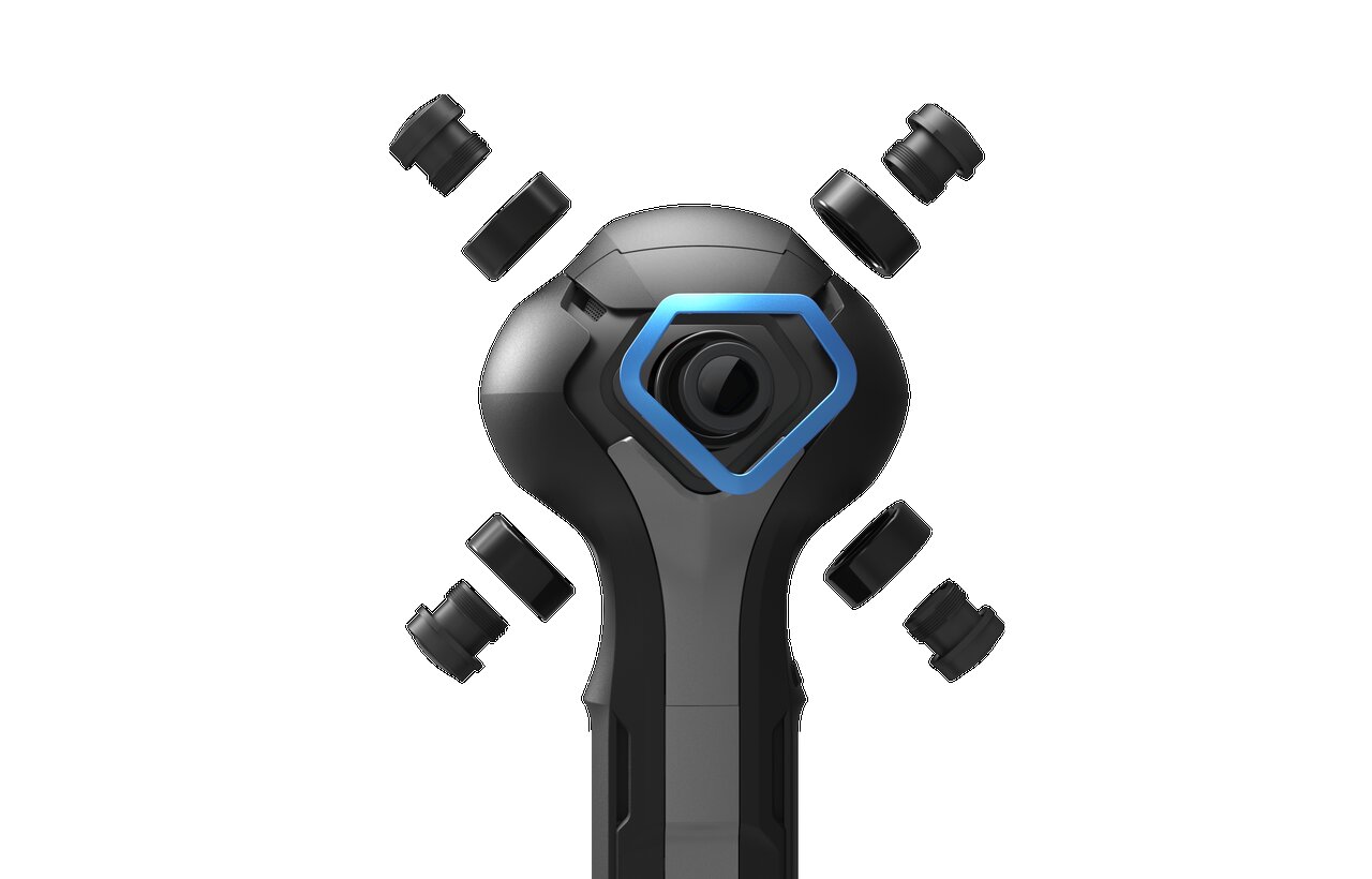
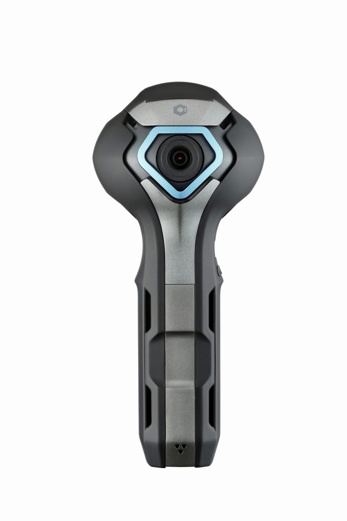
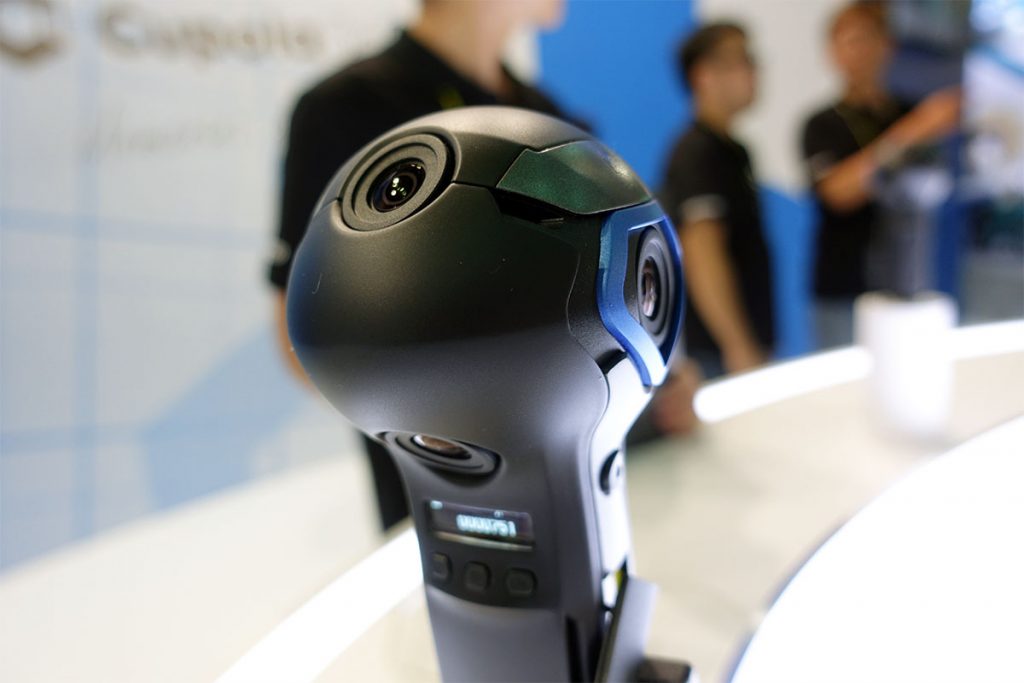
The Cupola360 is a 360-degree solution including Cupola360 Spherical Image Processor, 360-degree camera reference design, and accompanying apps for multiple applications and social media online sharing. With a focus on using 5MP six big-pixel high sensitivity sensors, the Cupola360 reduces the lens-distortion found in traditional solutions that use two fish-eye lenses. Cupola360 supports hardware in-camera (SoC) 360-degree image stitching and live-streaming of 4K 360-degree video which allows it to instantly start streaming video online without a tedious set-up process while most competitors’ cameras need post image stitching using computers or mobile phones. Additional features including 4K2K 30fps ultra-high resolution video; HEVC H.265/H.264 encoding; 3D anti-shake; face tracking, and apps which supports Android and iOS.

With built-in 2.4GHz and 5 GHz Wi-Fi and Cupola360 apps, users can easily share their 360-degree images and videos in the social media such as YouTube and Facebook. Moreover, accompany with VR Headset, the 360-dgree contents created by Cupola360 can bring amazing VR experience to the public. “There is no denying that in the future, people will relive precious moments in life via virtual reality consisting of 360-degree images, and therefore, we believe that a spherical 360-degree camera will soon become a must-have device in every household. ASPEED expects to surprise the public with Cupola360 solutions, so that people can experience first-hand how snappy, convenient and useful a 360-degree camera is in their daily lives.” said Chris Lin, Chairman of ASPEED Technology. ASPEED’s Cupola360 solutions will offer more diverse content and materials, providing users with opportunities to go back in time and live through life’s wondrous moments again, or a chance to escape from reality, enjoying the fantastic hyper reality created by themselves and others in the world.

ASPEED is now joining forces with industry partners to form a 360-degree camera eco-system powered by Cupola360. With a strong foothold in the exclusive 360-degree spherical image processor, ASPEED for the first time offers to its customers a suite of technologies that include SoC, built-in software, hardware and supporting smartphone apps. ASPEED hopes to build a 360-degree camera eco-system upon the integration of software and hardware systems, with the participation of industry partners. We believe the Cupola360 eco-system represents a revolutionary step forward for consumer-level 360-degree cameras and brings all those elements together with the newest ideas in hardware, software and social media.

Cupola360 Highlights

  • ASPEED Cupola360 Spherical Image Processor
  • Hyper-Stitching engine: In-camera stitching
  • Hyper-WDR Hardware Dynamic Range processing
  • Instant live-streaming
  • 5MP Six big-pixel high sensitivity sensor inputs
  • Output Image: 32MP pictures (8K)
  • Output Video: 4K 30 fps video (streaming & stored)
  • Connectivity: Wi-Fi 802.11 ac/a/b/g/n (2.4GHz / 5GHz)
  • H.265/H.264 compression
  • 2 TB addressable storage

The Cupola360 Spherical Image Processor solutions is now available for integration in consumer-grade portable devices by partners, and ASPEED is looking forward to discussing this during Feb25-28, MWC19 in Barcelona. Come to our booth to experience ASPEED’s cutting-edge products: Hall 5, Stand 5A61 Fira Gran Via, Barcelona. For more detailed information, please visit Cupola360.com

Virt2real Stereoscopic Camera kit with Raspberry Pi CM3+

Virt2real has launched its camera kit designed to function with an RPi Compute Module and 2x Raspberry Pi cameras. It moves from the original CM1 to the latest CM3+ for additional performance and compatibility. The camera board supports spatial awareness, 3D depth maps, and 3D video live streaming, among others. The StereoPi can be used for capturing, saving, live-streaming, and processing real-time stereoscopic video and images for robotics, AR/VR, computer vision, drone instrumentation, and panoramic video.

On Crowd Supply, the StereoPi is available in a Standard version for $89, and a $69 Slim model with a shorter 15mm build. The shorter build eliminates the real-world connectors for 10/100 Ethernet and 2x USB 2.0 ports and supplies the board a 40-pin GPIO connector. Both packages are void of the Raspberry Pi CM3, cameras, camera ribbon cables, or power and USB cables. A $125 Starter Kit is also available based on the Standard model.

StereoPi board

The Starter Kit has a second power cable and also a microSD card with the StereoPi Raspbian image and demos. Available also is a Deluxe Kit with dual wide-angle (160°) cameras. Additional accessories Kit for $25, offers 5cm cables for connecting the cameras to the StereoPi board. This substitutes the 10-20cm cables that are available for the V1 and V2 cameras. A USB, standard power cables, and two acrylic plates for mounting both standard and wide-angle cameras are available in the kit. The 90 x 40 x 23mm StereoPi board is fitted with LAN and dual USB ports, and also a micro-USB port for power and a USB header.

Detailed view of StereoPi

The board features an HDMI output port, a microSD slot, a 5VDC input, a manual power switch, and a 40-pin GPIO connector for Raspberry Pi I/O. The StereoPi image supports Python and example code. It also supports micro-USB delivered firmware updates. The board offers dual MIPI-CSI-2 camera connectors that support either the Raspberry Pi V1 or V2 cameras, and also Auvidea’s B101 HDMI to CSI-2 bridge module with HDMI input port. The camera connectors also support the optional wide-angle camera (5-megapixel Waveshare RPi Camera G).

Features & Specifications

The StereoPi is available on Crowd Supply in packages starting at $69. Packages ship Mar. 31, and shipping is free to the U.S. and cost  $10 to other countries. More product information can be found on the StereoPi Crowd Supply page and the Virt2real website.

Run Windows 10 on Raspberry Pi 3

Back to the year that Raspberry Pi 2 was introduced, Microsoft has announced it would support the platform with its slim edition of Windows 10 IoT, which works better on the new 64-bit RPi 3 models. But, what about running the full version of Windows 10 on RPi 3 or 3B+. This is what is promised by the WOA-Project with its new WoA-Installer.  According to Windows Latest, the open source WoA (Windows on Arm) Installer was announced in January following an earlier WoA release for the Lumia 950 phones.

Developer Jose Manuel Nieto Sanchez call the tool “super easy to use” and “no-hassle.” It requires a Raspberry Pi 3 Model B or B+, a microSD card (recomended A1 rating) and a Windows 10ARM64 image, which is linked to from the page where you get the download instructions. The installer needs a set of binaries and according to the author:

these binaries are not not mine [emphasis his] and are bundled and offered just for convenience to make your life easier, since this tool is focused on simplicity.

In conclusion the WoA Installer will allow you to run Windows 10 Arm 64 on the RaspberryPi 3 but comes with no performance promises and has yet to be further tested.

Install Windows 10 on Raspberry Pi 3 (ARM)

You can use this third-party installer if you already have a Raspberry Pi 3 Model B (or B+) and a MicroSD card with A1 rating. To install Windows 10 ARM on Raspberry Pi 3, please follow the steps below:

  1. Download the Windows 10 ARM image, WoA installer and Core Packages from here.
  2. Run WoA Installer and go to the Advanced section.
  3. Click on ‘Import Core Package’ option and select the package directly.
  4. After importing, you will be allowed to use deploy Windows option.

Let us know in the comments if you successfully deployed Windows 10 on Raspberry Pi and how this runs?

ODROID-N2 SBC features Hexa-core Amlogic S922X and $63 to $79 price tag

The ODROID-N2 SBC is a new generation single board computer that is more powerful, more stable, and faster performing than ODROID N1. The main CPU of the N2 is based on big.Little architecture which integrates a quad-core ARM Cortex-A73 CPU cluster and a dual core Cortex-A53 cluster with a new generation Mali-G52 GPU. Thanks to the modern 12nm silicon technology, the A73 cores runs at 1.8Ghz without thermal throttling using the stock metal-housing heatsink allowing a robust and quiet computer. The CPU multi-core performance is around 20% faster and the 4GByte DDR4 RAM is 35% faster than the N1. The N2’s DDR4 RAM is running at 1320Mhz while N1’s DDR3 was running at 800Mhz. The large metal housing heatsink is designed to optimize the CPU and RAM heat dissipation and minimize throttling. The CPU is placed on the bottom side of the PCB to establish great thermal characteristics.

Specifications listed for the Odroid-N2 include

  • Processor — Amlogic S922X (4x Cortex-A73 @ 1.8GHz, 2x Cortex-A53 @ 1.9GHz); 12nm fab; Mali-G52 GPU with 6x 846MHz EEs
  • Memory/storage:
    • 2GB or 4GB DDR4 (1320MHz, 2640MT/s) 32-bit RAM
    • eMMC socket with optional 8GB to 128GB
    • MicroSD slot with UHS-1 SDR104 support
    • 8MB SPI flash with boot select switch and Petitboot app
  • Wireless — Optional USB WiFi adapter
  • Networking — Gigabit Ethernet port (Realtek RTL8211F); about 1Gbps
  • Media I/O:
    • HDMI 2.1 port for up to 4K@60Hz with HDR, CEC, EDID
    • Composite video jack with stereo line-out and 384Khz/32bit audio DAC
    • SPDIF audio via 40-pin
  • Other I/O:
    • 4x USB 3.0 host ports (340MB/s typical)
    • Micro-USB 2.0 OTG port (no power)
    • Serial console interface
    • Fan connector
  • Expansion — 40-pin GPIO header (25x GPIO, 2x i2C, 2x ADC, 6x PWM, SPI, UART, SPDIF, various power signals, etc.)
  • Other features — RTC (NXP PCF8563) with battery connector; IR receiver; metal heatsink; 2x LEDs; optional $4 acrylic case
  • Power — 7.5-20V DC jack; 12V/2A adapter recommended; consumption: 1.8W idle to 5.5W stress
  • Dimensions — 90 x 90 x 17mm
  • Operating system — Ubuntu 18.04 LTS with Kernel 4.9.152 LTS and Android 9 Pie BSPs

Board details

Block diagram

Introduction Video

The Odroid-N2 will arrive in April about four months later than intended, but with a much lower $63 (2GB RAM) and $79 (4GB) price compared to the original Odroid-N1.

More information may be found on Hardkernel’s Odroid-N1 announcement and product page and wiki.

TinyWiFi 5G – A Clone of NanoPi NEO Air with 5GHz Wifi

Back in 2016, FriendlyARM launched the NanoPi NEO Air, an ARM-based board that featured Allwinner H3 processor, 2.5GHz WiFi, Bluetooth 4.0 LE, a camera DVP interface, and a ton of GPIO pins. The board was relatively powerful for it’s Nano size and it now costs around $28.

Fast Forward to 2019, we have a new board called the TinyWiFi 5G based around the same NanoPi NEO board but not developed by FriendlyARM. The TinyWiFi 5G is an apparent clone of the NanoPi NEO Air but comes with some upgrades. Cloning was one of the primary reasons that drastically improve the Arduino ecosystem and also help in crashing down prices of boards allowing makers and hobbyist to join the wagon.

TinyWiFi 5G - NanoPi Neo Air
TinyWiFi 5G – A Clone of NanoPi NEO Air with 5G WiFi

The TinyWiFi 5G is almost like NanoPi NEO Air board, with the same look but just one major significant difference – Connectivity. The NanoPi NEO Air board was capable of 2.4GHz WiFi 802.11n plus Bluetooth 4.0 LE thanks to its Ampak Ap6212 module, but the TinyWiFi replaces this module with the better dual-band Realtek RTL8821CS module that supports 802.11 b/g/n/ac (WiFi 5) and Bluetooth 4.2 LE.

The team behind the TinyWiFi 5G is a group of developers called TinyDebian and have also created a tool for building a bootable SD card image for ARM boards which is found in Github here.

According to tinyDebian, the developers created the board because

“2.4GHz channels are crowded, 5GHz channels are much better. Low-cost boards with 5GHz Wi-Fi are hard to find.”

Layout and Features

Board layout for the NanoPi Neo Air

Although little information is available for this board, it is expected that it will share virtually all specifications of the NanoPi NEO Air board. The NanoPi NEO Air usually comes with two different storage configuration (8GB or 32GB flash), but since nothing is specified for the tinyWiFi board, it is expected to carry the default 8GB storage option.

Expected specifications for the TinyWiFi 5G:

  • SoC – Allwinner H3 quad-core Cortex A7 @ 1.2 GHz with an ARM Mali-400MP2 GPU
  • System Memory – 512 MB DDR3
  • Storage – 8GB eMMC Flash + micro SD card slot
  • Connectivity – Dual-band 802.11b/g/n/ac WiFi 5 and Bluetooth 4.2 LE via Realtek RTL8821CS module, IPEX antenna connector
  • USB – 1x micro USB OTG port, 2x USB via headers
  • Camera – 1x DVP camera interface
  • Expansion headers
    • 24-pin header with I2C, 2x UART, SPI, PWM, and power signals
    • 12-pin header with 2x USB, IR pin, SPDIF, and I2S
  • Debugging – 4-pin header for serial console
  • Misc – Power and status LEDs
  • Power Supply – 5V/2A via micro USB port or VDD pin on the serial header
  • Dimensions – 40 x 40 mm

Low-cost boards with 5GHz WiFi are hard to find. This board is suitable for quick prototyping with 5GHz WiFi.

Neither documentation or images for this exact board is available instead of tinyDebian’s FriendlyArm wiki reference of the NanoPI NEO board as the documentation source that the board will work out of the box are same of the resources for the NanoPi Neo Air.

TinyWifi 5G NanoPi
NanoPi NEO Air Layout

It no denies that the TinyWiFi 5G which cost $59 on Tindie is way more expensive than the original NanoPi Neo Air board. Getting 5GHz will usually take you on the high end, but the high cost of the TinyWiFi 5G might be a drawback for the board. More information about the TinyWiFi 5G is available on the product page. 

TOP PCB Companies