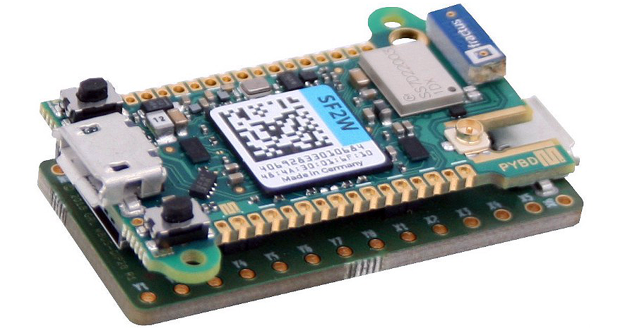
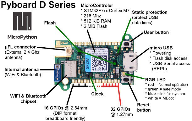
Pyboard D-series (aka Pyboard D, or just PyBD) board was introduced during the Micropython presentation at FOSDEM 2019 and it’s build around a faster STM32F7 Cortex-M7 MCU, with 512Kb of RAM, and 2Mb of Flash, as well as built-in WiFi and Bluetooth connectivity. It also features a pair of external Flash chips and a micro SD card slot for additional expansion options.
The board can be programmed with MicroPythoneither from the command line, copying the Python file to the board (seen as a USB flash drive from your computer), or via WiFi using WebREPL terminal client.
If you are not sure, what MicroPython is, continue reading. MicroPython is a lightweight version of Python 3 optimized to run on microcontrollers, which is described as a ByteCode + virtual machine + file system compiler for the BareMetal OS implemented on the microcontroller.
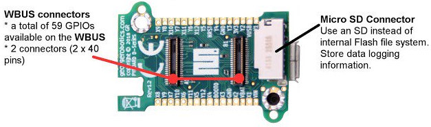
The WBUS connectors are also a new feature and will allow you to stack add-ons boards. For example the WBUS DIP28 or DIP68 boards are exposing respectively 28 and 68 I/O pins, and they can take one or more sensor board(s) via other smaller 2x 10-pin sensor board connectors.
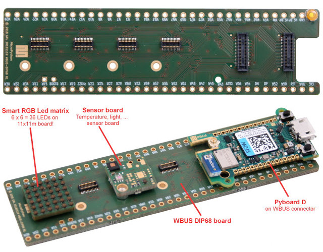
WBUS DIP68, Pyboard D, Sensor Board, and RGB LED Matrix (image source: shop.mchobby.be)
There’s no details yet on pricing, or when the board will be released, however some on the MicroPython forum say that it could hit the market in a few days or weeks.
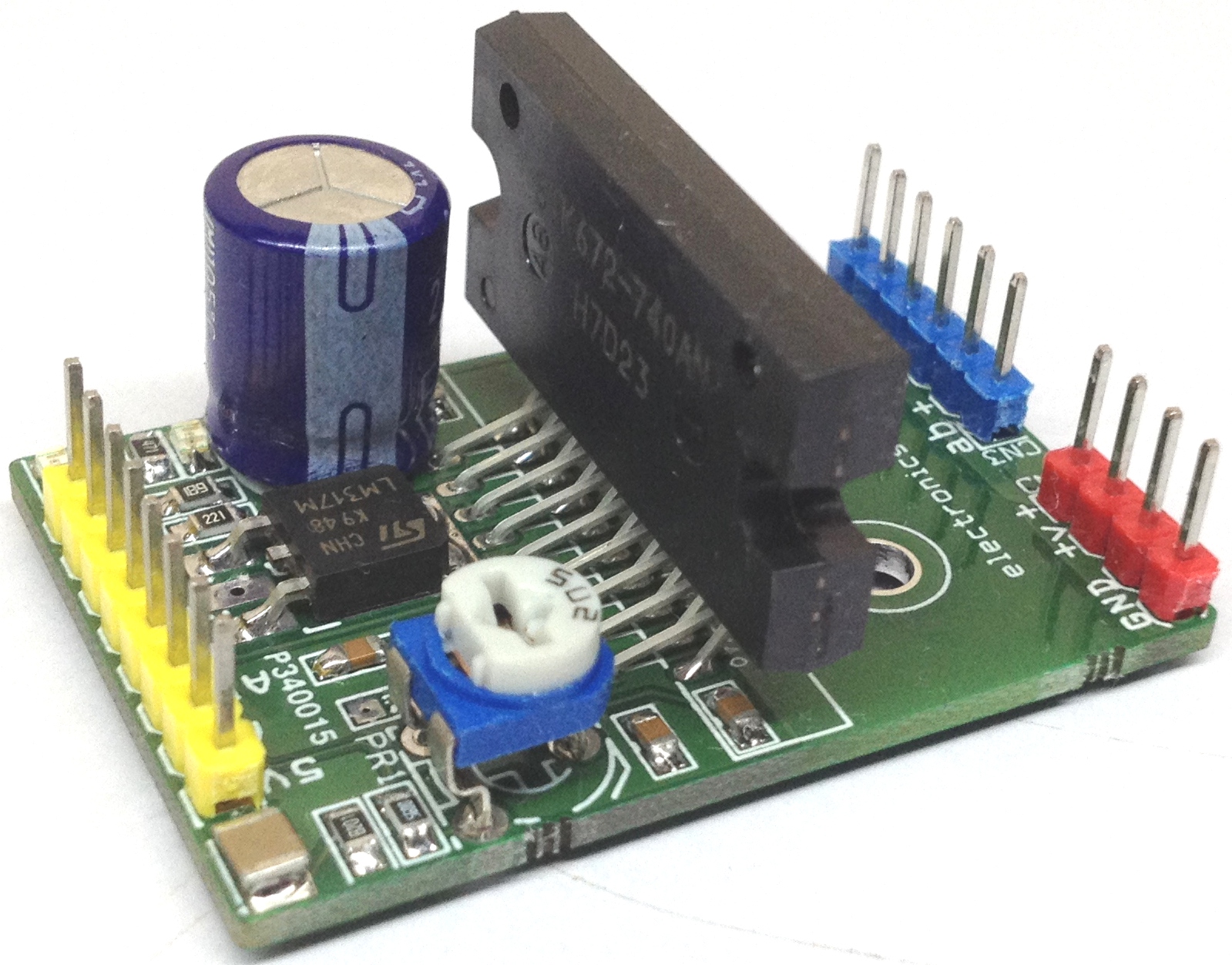
The project published here is a high-performance Unipolar stepper motor driver that offers PWM controlled high current output. An Arduino board and the project published here can be combined to create a good Unipolar stepper motor driver with micro-stepping, supply 36v DC and load current up to 4A. This board requires a sequence of 4 phase pulses which can be feed and generated using Arduino or any other microcontrollers. IC incorporates various functions like built in over current detection, over heat output OFF, fault output (active low) when over current or over heat detected, and also has built in power on reset. LED D2 is the power indicator, LED D1 indicates a fault. PR1 trimmer potentiometer provided to set the current. Refer to datasheet of STK672-740 for pulse sequence and timing information. The projects supports 5 Wire, 6 Wire and 8 Wire Stepper Motors in unipolar mode.
4A PWM Controlled Unipolar Stepper Motor Driver using STK672-740 – [Link]
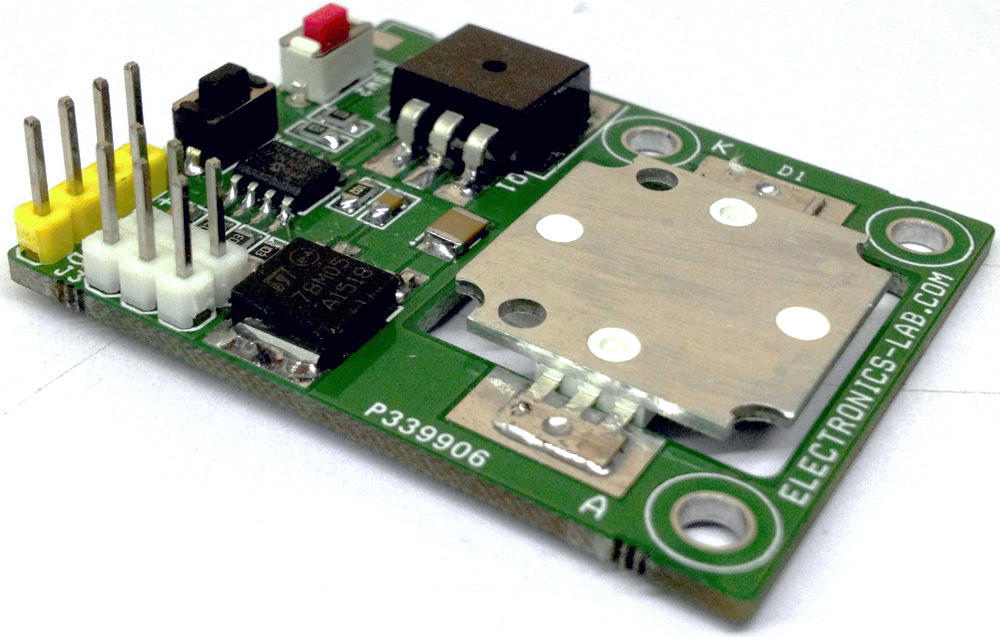
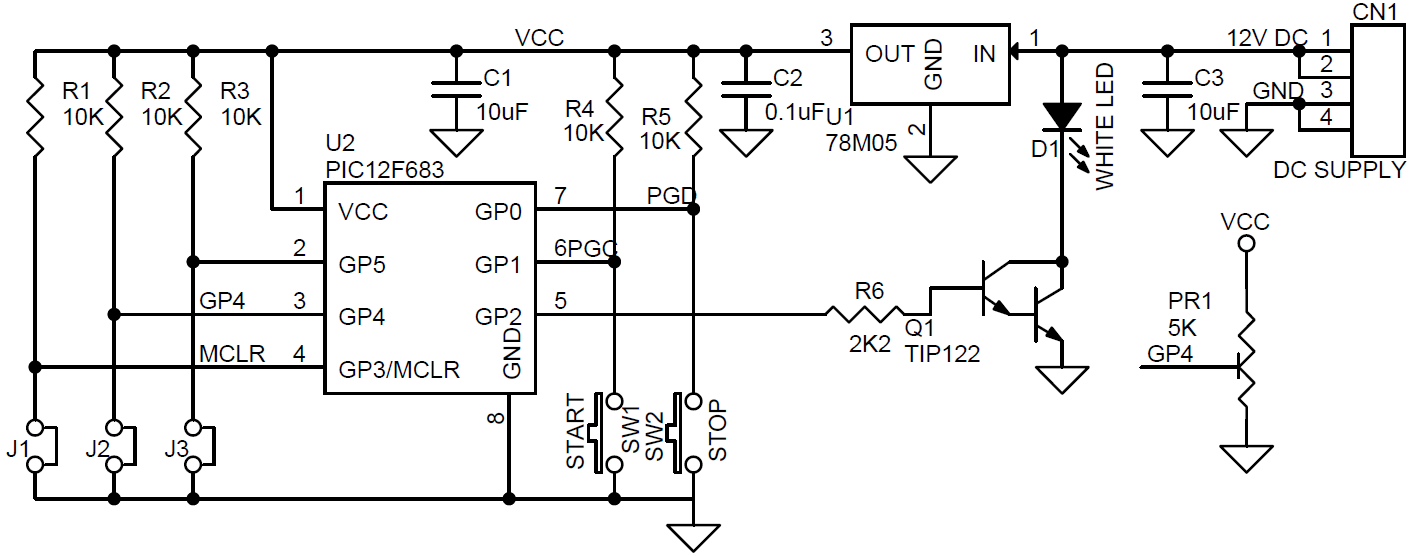
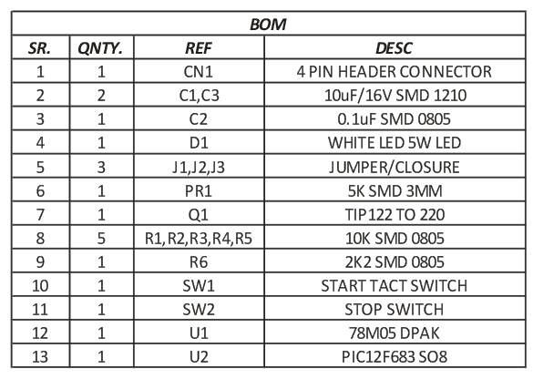
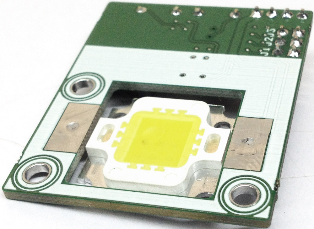
The project described here is small 5W LED driver, that can be used in variety of applications by changing the mcu code. The example code provided is a simple digital toggle switch using two tactile switches. One switch is used for power ON and the other for OFF. The on board small trimmer potentiometer helps in development of LED dimmer, jumper can be used for LED on/off timer projects. PIC12F683 from Microchip is the heart of the project, TIP122 NPN BJT helps to drive the LED. It is advisable to used large size heat sink for the LED.
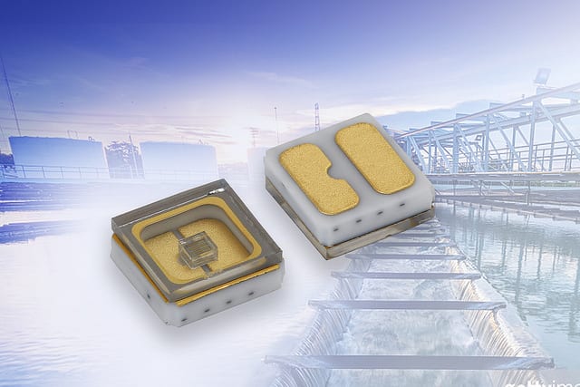
Ceramic Device Features Radiant Power to 18 mW in Compact 3.5 mm by 3.5 mm by 1.2 mm SMD Package
Vishay Intertechnology, Inc introduced a ceramic mid-power ultraviolet (UVC) emitting diode for sterilization, sanitation, and purification applications. Featuring a quartz window, the Vishay Semiconductors VLMU35CM..-280-120 delivers an extremely long lifetime in a compact 3.5 mm by 3.5 mm by 1.2 mm surface-mount package.
Designed to replace mercury UVC lamps, the device released today offers an emission angle of ± 60° and radiant power to 18 mW at 100 mA without the need for an external lens. Built on AlGaN technology, the VLMU35CM..-280-120 features forward current up to 150 mA, forward voltage down to 4 V, and a wavelength range of 270 nm to 290 nm.
The emitter diode’s specifications make it ideal for water and air purification, physical surface sterilization, medical disinfection, and portable sanitizers. RoHS-compliant, halogen-free, and Vishay Green, the VLMU35CM..-280-120 is compatible with reflow soldering processes and features a Moisture Sensitivity Level of 3 in accordance with J-STD-020.
The project described here is small 5W LED driver, that can be used in variety of applications by changing the mcu code. The example code provided is a simple digital toggle switch using two tactile switches. One switch is used for power ON and the other for OFF. The on board small trimmer potentiometer helps in development of LED dimmer, jumper can be used for LED on/off timer projects. PIC12F683 from Microchip is the heart of the project, TIP122 NPN BJT helps to drive the LED. It is advisable to used large size heat sink for the LED.
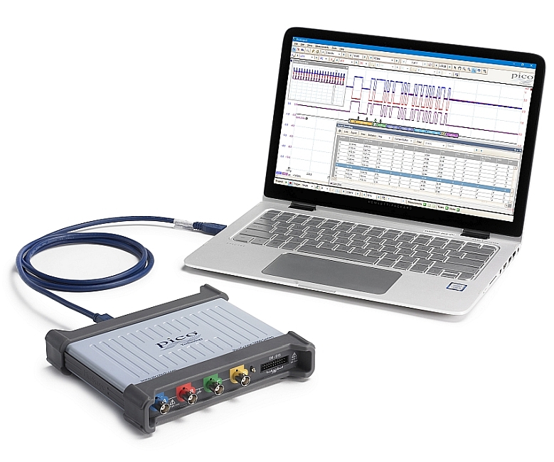
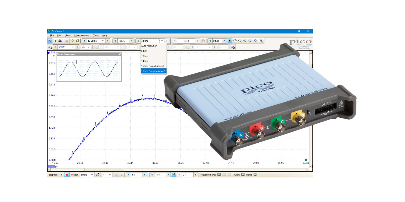
Today’s electronic designs employ a wide range of signal types: analog, digital, serial (both high- and low-speed), parallel, audio, video, power distribution and so on. All need to be debugged, measured and validated to ensure that the device under test is functioning correctly and within specification.
To handle this variety of signal types, PicoScope 5000D FlexRes hardware employs multiple high-resolution ADCs at the input channels in different time-interleaved and parallel combinations to optimize either the sampling rate to 1 GS/s at 8 bits, the resolution to 16 bits at 62.5 MS/s, or other combinations in between – you select the most appropriate hardware resolution for the requirements of each measurement.
2 and 4 channel models are available, all featuring a SuperSpeed USB 3.0 connection, providing lightning-fast saving of waveforms while retaining compatibility with older USB standards. The PicoSDK® software development kit supports continuous streaming to the host computer at rates up to 125 MS/s. The product is small and light, and operates silently thanks to its low-power fanless design.
Specifications
FlexRes 8 to 16-bit hardware resolution
Up to 200 MHz analog bandwidth
1 GS/s sampling at 8-bit resolution
62.5 MS/s sampling at 16-bit resolution
Up to 512 MS capture memory
16 digital channels on MSO models
130 000 waveforms per second
Built-in arbitrary waveform generator
18 serial decoding protocols as standard
Up to 200 MHz spectrum analyzer
Software
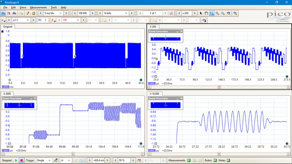
PicoScope 5000D Series oscilloscopes have waveform capture memories ranging from 128 to 512 million samples – many times larger than traditional benchtop scopes. Deep memory enables the capture of long-duration waveforms at maximum sampling speed. In fact, the PicoScope 5000D Series can capture waveforms over 500 ms long with 1 ns resolution. In contrast, the same 500 ms waveform captured by an oscilloscope with a 10 megasample memory would have just 50 ns resolution.
Overview Video
PicoScope 5000D Series Wins Elektra 2018 “Test Product of the Year” award
We are honoured that the PicoScope 5000D Series has been recognised with this prestigious Elektra award,” said Trevor Smith, Business Development Manager for Test & Measurement products at Pico. “Introduced on 4th June 2018 the 5000D Series builds on the success of the previous generation PicoScope 5000A/B Series flexible resolution oscilloscopes. The 5000D gives designers and test engineers the versatility they need to make measurements on the wide range of waveforms encountered in today’s embedded systems.
The PicoScope® 5000 Series prices start from ~€1000 for the 60MHz – 2 channel oscilloscope and it is available from various distributors online.
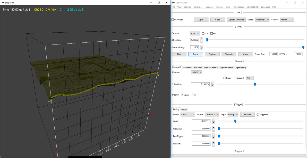
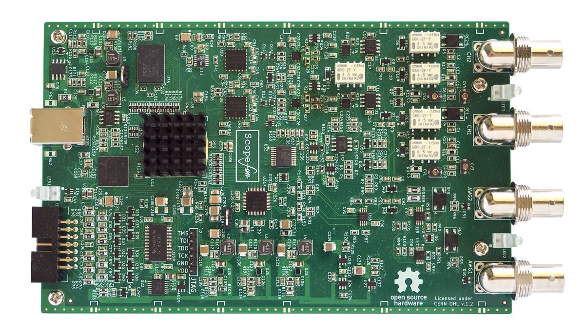
ScopeFun in an open source, all-in-one instrumentation platform. It includes an oscilloscope, arbitrary waveform generator, spectrum analyzer, logic analyzer, and digital pattern generator.
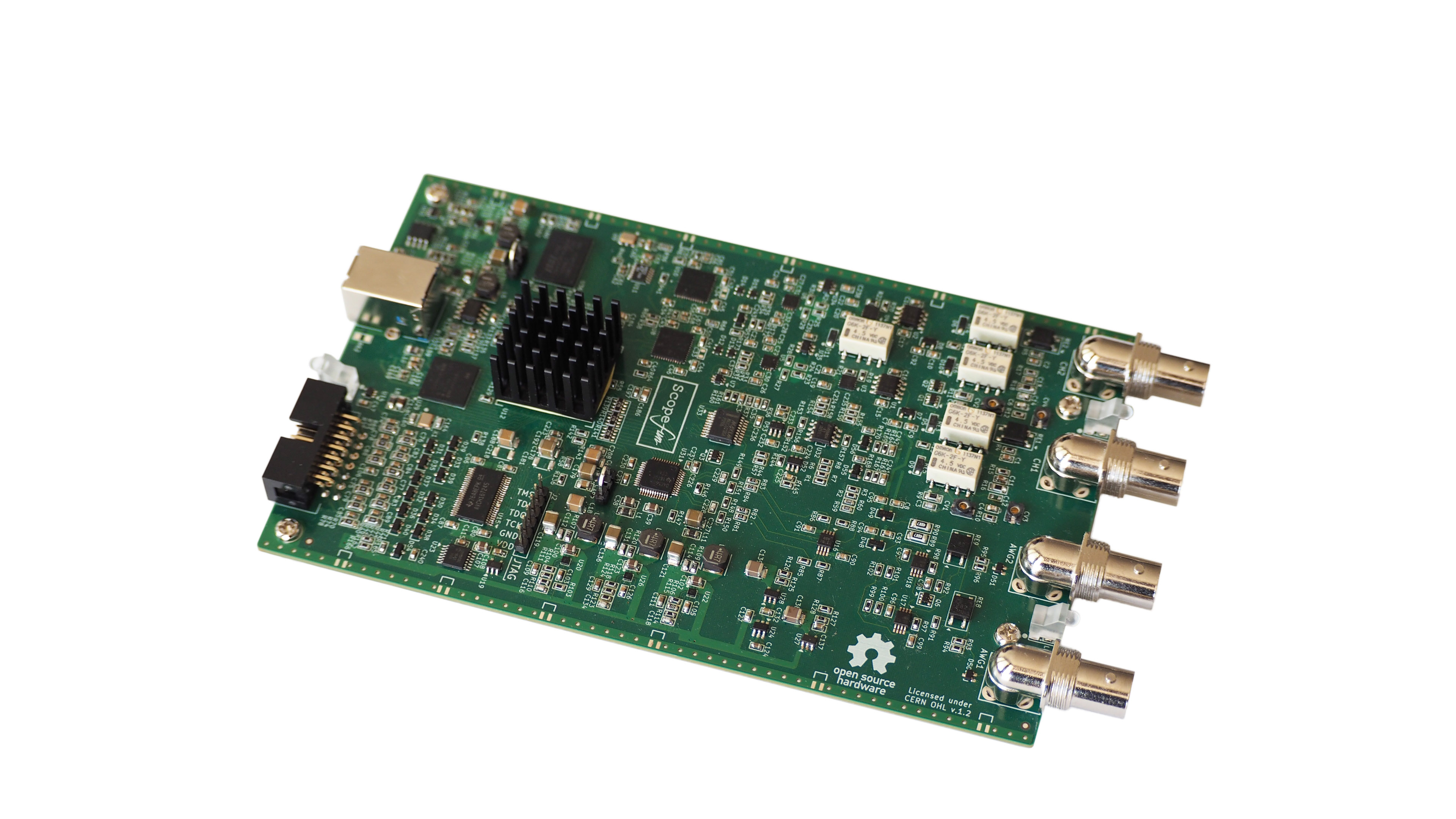
Hardware
Hardware is built around Xilinx Artix-7 FPGA with an onboard RAM available for buffering samples (512 MB DDR3 SDRAM). All hardware settings are controlled via software GUI. USB connectivity is provided via Cypress’s FX3 USB 3.1 Gen1 chip. Hardware is USB powered which eliminates the need for additional power supply. Below you can find more information about individual hardware components.
Oscilloscope
Two analog channels are available as oscilloscope inputs. Both oscilloscope channels are protected against overvoltages up to +/- 50 V. Input coupling selection is available (DC, AC, GND) and is controlled via program GUI. Input signals are buffered via analog front end for impedance, level (gain) and offset adjustments. Each analog channel is sampled at 250 Msps with 10-bit analog-to-digital converter (ADC). Two ADC’s can be configured for sampling in interleaved mode which provides a single channel sampling speed of500 Msps. Digital samples are processed by FPGA which also contains trigger logic. When trigger condition is met, samples are transferred to onboard DDR3 SDRAM which provides buffer length of 128 Mega samples per channel. Hardware also supports Equivalent Time Sampling (ETS). For this purpose an analog trigger signal is sampled inside FPGA LUT delay line to determine exact time of trigger event relative to the ADC sampling clock. This provides a sampling speed of2 GSps for repetitive signals.
Waveform Generator
There are two generator outputs with which can generate voltages up to 4 Vpp. Both AWG channels are protected against short circuit and overvoltage (+/- 25 V). Generator channels have 50 Ohm output impedance which allows connection to various equipment. User can select waveform shape, frequency, level and offset via program GUI and settings are immediately reflected in FPGA control registers. Digital samples are generated inside FPGA at 200 Msps per channel and transferred to dual digital-to-analog converter (DAC). Simple signals are derived from counters. Sine wave output is generated with the help of CORDIC algorithm, so that outputs of arbitrary frequency can be obtained. User can also provide a custom waveform sample data and upload it to FPGA internal memory (BRAM).
Logic Analyzer / Pattern Generator
12-bit digital interface is sampled at 250 Mhz and is logically divided into two 6-bit channel groups. Each channel group can be independently selected as input (Logic analyzer) or output (Pattern generator). Digital interface voltage can be adjusted – ranging from 1,25 V to 3,3 V, but inputs are designed to accept also 5 V. Selected interface voltage is also available on dedicated output pins and can be used as voltage supply. Custom digital samples for pattern generator can be uploaded to FPGA and internal clock divider is available to control the output frequency. It is also possible to override individual outputs with a logic ‘LOW’ or ‘HIGH’ at any time.
Voltage ranges (with 1× probe): 10 mV to 2 V per division
Memory depth: 128,000,000 samples per channel
Arbitrary Waveform Generator
Channels: 2
Update rate: 200 Msps
Resolution: 12 bits
Output voltage: 4 Vpp
Custom waveform length: 32,768 samples per channel
Spectrum Analyzer
Channels: 2
Frequency range: DC to 125 MHz
Logic Analyzer
Channels: 12 (six input + six output; or 12 input; or 12 output)*
Maximum sampling rate: 250 Msps
Memory depth: 128,000,000 samples per channel
Digital Pattern Generator
Channels: 12 (six input + six output; or 12 input; or 12 output)*
Maximum sampling rate: 250 Msps
Custom waveform length: 32,768 samples per channel
Primary Components
FPGA: Xilinx Artix-7
Memory: 512 MB DDR3 SDRAM
Connectivity: Cypress FX3 USB 3.0
Software
Server mode: remotely connect to ScopeFun hardware via IP network
Python API: read samples and control ScopeFun hardware directly from Python
Advanced signal rendering: 3D frame history and virtual persistence
* The logic analyzer and digital waveform generator share the same 12 channels.
Software
Oscilloscope software is designed to run on all major desktop operating system. 32 bit and 64 bit. This includes Windows 7, 8 and 10, all Linux systems and Mac OSX operating systems.
Introduction Video
Presentation Video
The project is already funded on Crowdsupply and more information can be found on the project homepage.
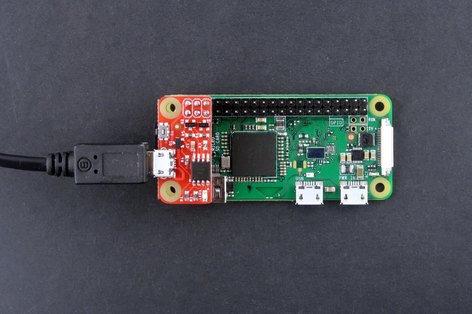
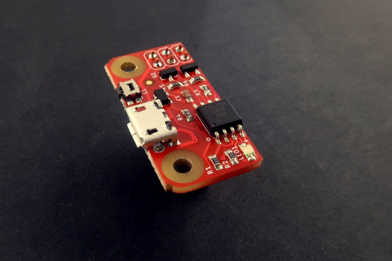
The PiWatcheris a very small board that helps you fully shut down or reboot a Raspberry Pi, in case of an incident or simply for power saving purposes. You can even program your PiWatcher to shut down and automatically reboot your Pi a few minutes or hours later. In essence, the PiWatcher is a programmable watchdog circuit for the Raspberry Pi, usable with the humble Pi Zero up to the power-hungry Pi 3.
The board must be fitted on the first 6 pins of the Raspberry GPIO header and plugged into a micro USB power supply suitable for the Raspberry Pi in use. The board will then switch on or off the power provided to the Raspberry Pi based on instructions it receives through I2C. The board also features a miniature tact switch to allow manual control.
The board is available on Tindie for purchase, and compatible with the Pi Zero, Pi 3 — you’ll just need to add the proper micro USB power supply!
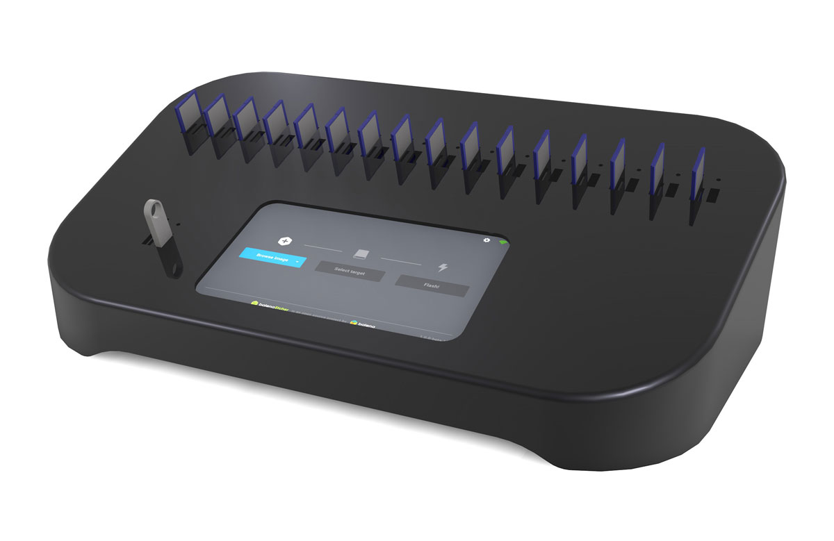
Balena’s Etcher Pro is a stand-alone hardware device that allows you to copy data to multiple cards or usb disks at once, at high speeds. Compared to conventional Disk Duplicator, Etcher Pro is faster and cheaper, easier to use and equipped with features, to enable you do much more than just copy SD Cards. Balena has been developing the duplicator for close to a year, and are currently looking at deploying the device in April or May 2019.
The device can copy images to bulk SD cards, micro SD cards, USB drives, and external hard drives to 16 destinations in one connection, through its USB 3.0 ports and SD card sockets. It enables flashing firmware, for SBCs equipped with eMMC like the Raspberry Pi Compute Module and BeagleBone Black.
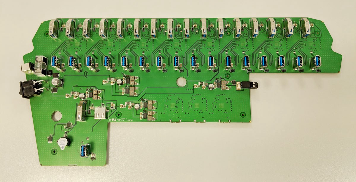
The EtcherPro mainboard is highly equipped with USB 3.0 ports, totaling 34 in number, which includes 16 modular ports on the top of the board to allow for easy access to the SD card readers, without causing restrictions to the ports positioned below. For the choice of processor board, Balena tried UP Squared, Banana Pi, Sapphire, ODROID-XU4, and Rock960, but due to some issues which wasn’t expatiated on, they dropped those options and finally went with an NXP i.MX 8 compute module.
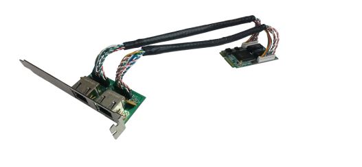
The board exploits the i.MX 8 compute module, both wired and wireless Ethernet, and also RGB LED indicators for each slot. If the boards 34 ports are not enough , you can daisy chain multiple EtcherPro docking stations together for increased productivity. The company says you can add up to 10 or more EtcherPro devices. Test carried out by Balena shows the device clocks at at 75MByte/s per port, which is quite impressive.
The EtcherPro mainboard features 34 USB 3.0 ports, modular SD card slots, as well as both wired and wireless Ethernet.
The first production batch is expected for Q2 2019, and Balena is planning on placing a $990 price tag on the EtcherPro upon its release. Similar devices like the EtcherPro on the market cost about 50% more, and do not offer the versatility, and efficiency of the EtcherPro. So the $990 price tag on the EtcherPro is quite a good bargain.