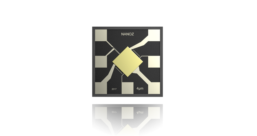
With the latest Nanoz Gas sensors you have the possibilities to include the sensor in watches, phones etc. Our sensor has 4 times wider detection range than other sensors and even it is one of the smallest in the market (just 1.8 mm for each side and 0.45 mm thick) we managed that our sensors are able to be Selective. (Patent) Furthermore it consumes only 1/10 energy compared to similar sensors. Can you imagine the endless possibilities of its application?
Based on metal oxide technology, the sensor is not only incredibly small but it is also able to detect a multitude of gases, including but not limited to CO2, CO, CH4, BTEX, and NO2.
The company behind Nanoz aims to add it’s sensor on 8-9% of the mobile phones that are sold by 2020.
The world smallest nano chip
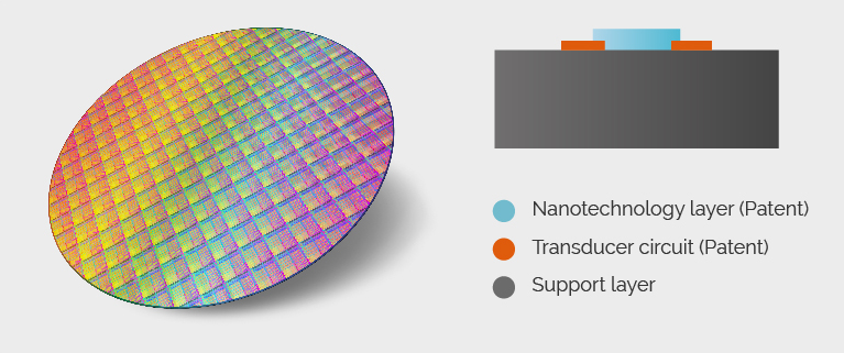
Our Technology Is Build Upon The Just Released
Mox (Metal Oxide) Technology.
So What Does Our Sensor Makes Us Different?
Selectivity
The Most Sensitive
The Least Energy Consuming Of The Market In Mox Technology
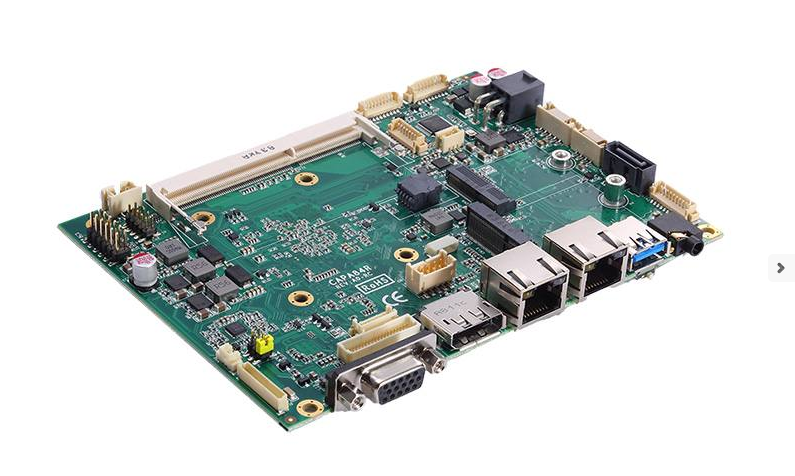
3.5″ Embedded SBC with Intel® Celeron® Processor J1900/J1800, LVDS, VGA, DisplayPort, Three GbE LANs and Audio.
CAPA84R, is a fanless 3.5-inch embedded motherboard powered by the Intel® Celeron® processor J1900 quad-core or J1800 dual-core. The CPU is located at the rear side of the motherboard, which further aids the heat-extraction process and simplifies maintenance procedures. This fanless embedded board was designed for operational efficiency in rugged architecture with a wide operating temperature range of –20°C to +70°C. The CAPA84R also comes with rich I/O connectors, stunning graphical performance and an emphasis on expandability, making it a performance-driven solution for Industrial IoT and M2M related applications.
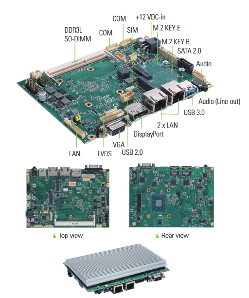
The CAPA84R supports one 204-pin DDR3L-1333 SO-DIMM socket with up to 8GB of system memory. There are also one SATA-300 port and one M.2Key B supporting SATA for storage. The 3.5-inch embedded SBC with the Intel® integrated Gfx graphics is made to bring a true high definition visual experience with dual display configurations through the DisplayPort, 18/24-bit dual-channel LVDS and VGA.
We have dedicated ourselves to developing first-rate embedded boards to ensure all clients get the best value from our products. The industrial-grade CAPA84R provides enhanced computing capability, excellent graphics yet low power consumption to serve the needs of diverse industrial IoT applications,” said Michelle Mi, a product manager of ECSE Division at Axiomtek. “With the impressive graphical performance, the CAPA84R provides an ideal solution for customers seeking performance demanding digital signage or infotainment system applications. The 3.5” motherboard also has three Gigabit Ethernet ports and one USB 3.0 port which support industrial cameras for machine vision applications.
Furthermore, this 3.5-inch embedded board adopts a rich array of I/O interfaces including two USB 2.0 ports, one USB 3.0 port, three Gigabit Ethernet ports with Intel® Ethernet controller i211-AT, one RS-232/422/485 port, one RS-232 port, HD Codec audio port and 8-in/out DIO port. The CAPA84R is expandable with one M.2 Key E connector supporting PCIe x1 interface for Wi-Fi modules and one M.2 Key B connector supporting USB 2.0 interface for cellular modules. The 3.5″ embedded SBC also utilizes advantages of watchdog timer and hardware monitoring features to ensure reliable operation. Moreover, the CAPA84R runs on 12V DC power, supporting auto power-on function.
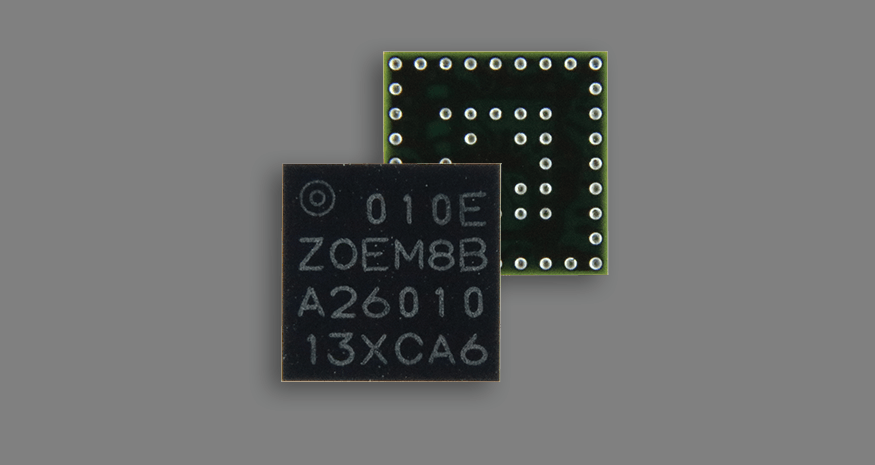
Ultra small, super low power u-blox M8 GNSS SiP module.
ZOE-M8B is u-blox’s ultra small, highly integrated GNSS SiP (System in Package), measuring just 4.5 x 4.5 x 1.0 mm. Making use of the Super-Efficient (Super-E) mode, ZOE-M8B offers an ideal balance between miniature size, low power consumption and good GNSS performance. ZOE-M8B uses up to 2.5 times less power than its pin-to-pin compatible counterpart, ZOE-M8G (running in 1 Hz full power mode), while still maintaining good positioning and speed accuracy.
An average power consumption over a typical 30-minute track will be as low as 25 mW. This is true even when using an industrial antenna design with moderate-to-low signal levels. Super-E has a default performance setting for the best balance between power vs. performance.
It also has a power save setting for additional power savings with potential compromise on performance. The TCXO-based ZOE-M8B integrates a front-end SAW filter and an additional front-end LNA for increased jamming immunity and easier antenna integration. A passive antenna can be used to provide a highly integrated system solution with minimal eBOM.
Ultra small, ultra low power GNSS SiP with Super-E mode
Ultra small size SiP (System‑in‑Package) 4.5 x 4.5 x 1.0 mm
Fully integrated and complete solution, reducing total design efforts
As low as 12 mW power consumption thanks to Super‑E mode
Ideal for passive antenna, due to built‑in SAW and LNA
High accuracy thanks to concurrent reception of up to 3 GNSS
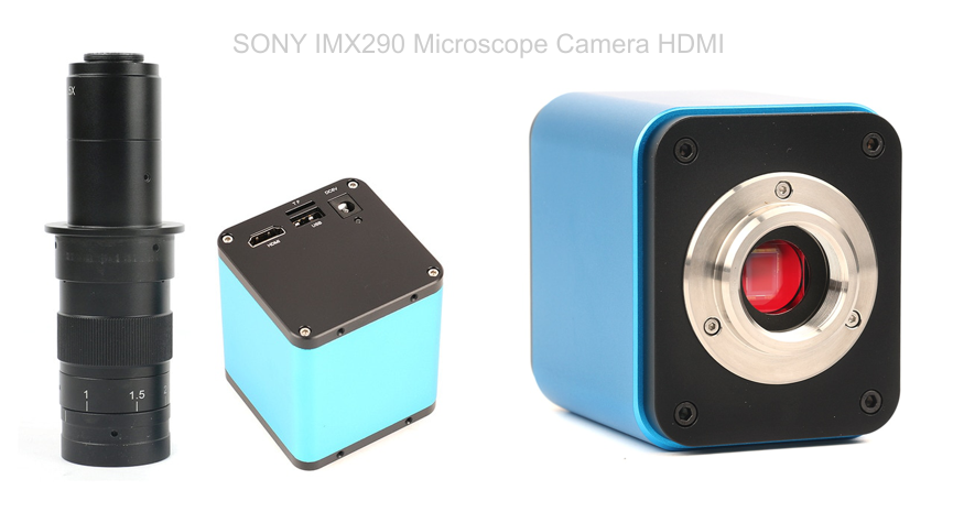
This is an Autofocus SONY IMX290 Industry Microscope Camera with HDMI output, ideal for PCB inspection and board repair work. This microscope has some great reviews among professionals and hobbyists and is priced at €466 without the standing base, monitor and LED light. It’s resolution is 1080PFULL HD@60FPS with integrated UI menu which can be easily controlled with a mouse connected to the camera. When observing objects of different heights (MAX 10CM), you do not need to adjust the lens’s working distance as autofocus will engage. Also, when you adjust the lens’s magnification, you do not need adjust the lens’s working distance for the same reason. The image quality on a computer monitor looks crispy clear as you can see on Dave’s Video Review below and this can take your repair and assembly work at another level.
Specifications
Sensor: SONY IMX290
Image Sensor : Colour CMOS
Pixel size : 1/2.8〞
Menu : Fully digital UI design
Method of Operation : Mouse
Lens interface : C/CS-type
Power DC : DC5V
Output method : HDMI
White Balance : Auto / Manual / One-push control
Exposure : Auto / Manual
Display Frame rate : 1080P@60fps
Scanning method : Line by line scanning
Shutter Speed : 1/50s(1/60s)~1/10000s
Operating Temperature : 0℃~50℃
Magnification / Zoom : Support
Saving function : Support TF card
C-MOUNT Lens
Working distance: 95mm
Zoom c-mount Lens
0.5X C-mount adapter
Zoom ratios: 6.5:1
Objective Magnification Power by 0.7 – 4.5X(about 10 – 180X on the display)
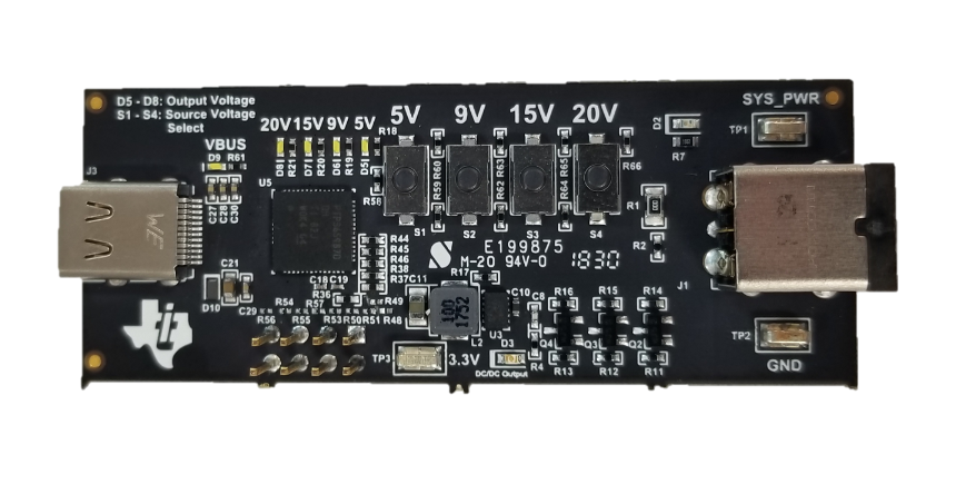
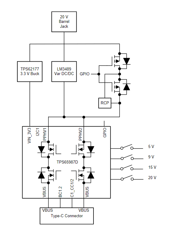
This USB Power Delivery (PD) reference design will allow users to implement system that require more than 100 W as a power source while also highlighting the industries lowest RDSon solution.
The design can output all four of the standard USB Type-C PD source voltages of 5 V, 9 V, 15 V, and 20 V. In standard Type-C PD operation, the design will output up to 20V/4A. When Texas Instruments Power DUO mode is enabled, the design will be able to output up to 20V/10A while simultaneously lowering the RDSon by a factor of two.
Features
High Power USB Type-C PD Source
Barrel Jack to Type-C: 5-V, 9-V, 15-V, or 20-V Charging up to 4 A
Up to 20-V at 10 A through Texas Instruments Power Duo Mode
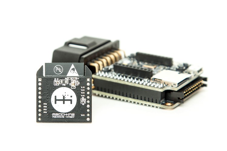
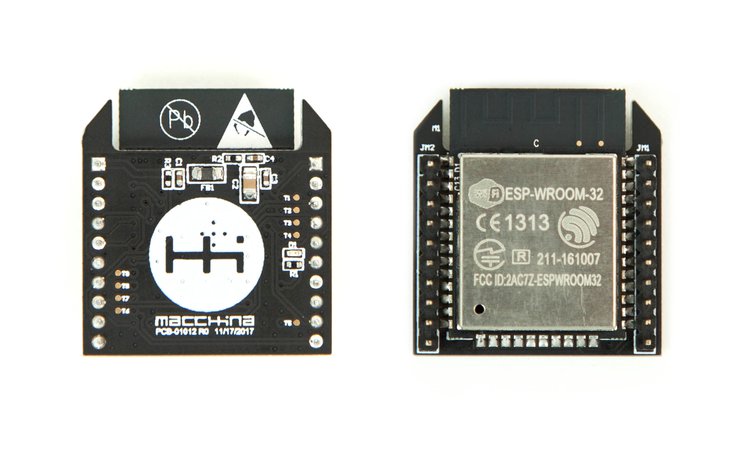
SuperB is an open source, Bee–compatibleESP32 module for quickly and easily adding Wi-Fi and Bluetooth to your project. It combines the popularity of ESP32 with the XBee form factor to achieve an easy way of adding wireless connection to your board. It was originally build for use with Macchina M2 ODB2 scanner, check details below.
SuperB marries two of hardware’s ubiquitous names – the “Bee” form factor and ESP32. The Bee form factor was derived from DIGI’s XBee industrial grade IoT boards. This form factor has long been used to add wireless connectivity to hardware across the board. But in the maturing market of connected items, two protocols stand as required: Wi-Fi and Bluetooth. ESP32 brings both, and in an easy-to-use package – giving maximum flexibility to your existing hardware and for your next generation of modular, extensible products.
Features & Specifications
Open source hardware
XBee form-factor compatible (3.3 V levels, UART, SPI and GPIOs broken out to headers)
Based on popular ESP32 SoC
Wi-Fi (802.11 b/g/n)
Bluetooth (Classic and BLE)
Programmable with many tools, including Arduino IDE
OTA (Over-the-Air) flashing capable
Dual Core processor up to 240 MHz
Integrated 4 MB flash – we may upgrade this to 16 MB
Sleep current is less than 5 μA
Fully certified with integrated antenna and software stacks
One programmable LED
Macchina M2
SuperB was originally designed for use with another Macchina product – the M2, which is the open source OBD2 connector and dev board for car hacking. SuperB was designed based on feedback from the car hacking community, but motivated by our desire to avoid tripping over so many wires ourselves. M2 is also available for purchase during this campaign, so you can get the complete kit. It’s great for vehicle tuning, diagnostics, total customization, security, telematics, or prototyping, and works with just about any car manufactured after 1996.
The campaign is live on crowdsupply.com and has 25 days to go with plegdes starting at $23.
FDK CORPORATION will begin sample shipment of oxide based all-solid-state battery using high electrochemical potential cathode material “lithium cobalt pyrophosphate (Li2CoP2O7)” which was jointly developed with Fujitsu Laboratories Ltd. February 2017.
While applications using various batteries such as IoT devices and wearable devices expand and progress, the specifications required for batteries are becoming increasingly diverse, and, in particular, there is increasing interest in high energy density and safety performance. Respond to these needs all-solid-state batteries are attracting attention as next generation battery, FDK has been continued to develop all-solid-state battery using high electrochemical potential cathode material “lithium cobalt pyrophosphate (Li2CoP2O7)” with features such as high energy density, superior safety performance, and long life.
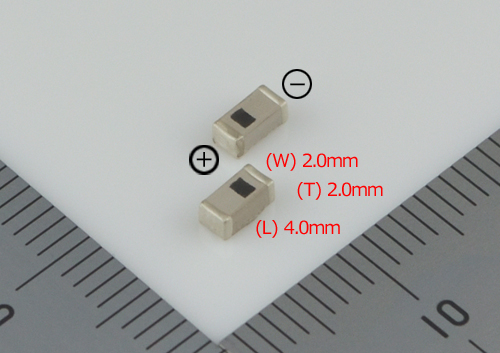
FDK developed ultra small size all-solid-state battery with capability of high voltage output using high electrochemical potential cathode material “lithium cobalt pyrophosphate (Li2CoP2O7)” and begins sample shipment from 20 December, 2018.
This battery is SMD (Surface Mount Device) type, so they can be mounted as one of the electronic parts, contributing to miniaturization of equipment and reduction of surface mounting cost.
Features
Small size SMD type – Dimension of Sample (L) 4.0mm x (W) 2.0mm x (T) 2.0mm
High voltage, High capacity – High voltage 3.0V, high capacity 140μAh
High energy density – Energy density 26mWh/cm3
Wide operating temperature range – Operating temperature range -20 – +105℃
High safety and environmental adaptability – Use inflammable materials
Use stable oxide sintered ceramics (sulfide free)
Main application
IoT device
Wearable device
Backup power supply for semiconductor products such as Real Time Clock (RTC)/SRAM/MCU
Industrial equipment used in harsh environments (high temperature, vacuum etc.), measurement of automobile equipment application, wireless modules etc.
In parallel with sample shipment of this product, FDK will continue to increase the capacity of this product for further expansion of applications.
Scheduled to ship samples with high capacity in April 2019.
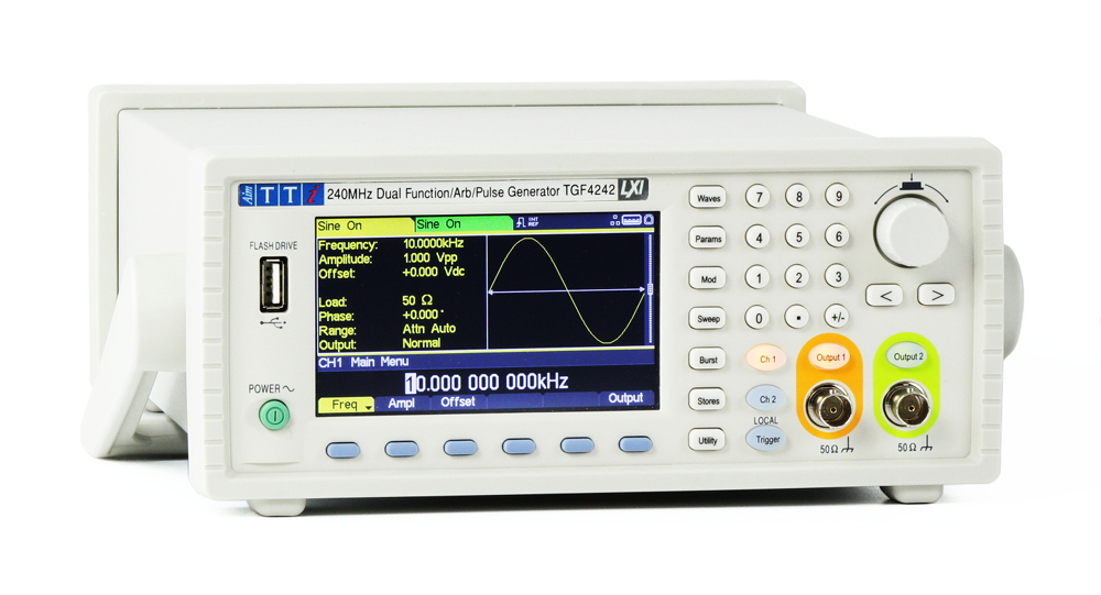
Sine frequency up to 240MHz with 1μHz resolution Up to 100MHz high resolution pulse generator Arbitrary waveforms up to 16bits at 800MSa/s Wideband noise generator.
The TGF4000Series out-performs other generators in its price range by offering models at up to 240MHz with low harmonic distortion and phase noise. Audio band THD is significantly better than similar generators at just 0.05%. The pulse generator function offers an exceptional pulse width resolution of 100ps over a period range from 10ns to 1000s. The pulse edge speed is independently variable from 3ns to 800s. Pulse jitter is dramatically lower than any comparable generator at only 30ps. The two channels can be operated completely independently as if they were two separate generators. Coupled operation is available for frequency, amplitude and output on/off enabling simultaneous output changes on both channels. Relative phase can be set from -360 degrees to +360 degrees with 0.001 degree resolution.
The main outputs can provide up to 10V pk-pk into 50Ω (20V pk-pk EMF) for frequencies up to 80MHz. High levels of DC offset can be set in conjunction with low signal levels, and the attenuator can be fixed to prevent glitches when changing levels. Amplitudes can be entered as peak to peak voltage plus offset or in terms of high level and low level. The amplitudes are shown relative to a 50Ω load impedance or as the open circuit EMF values. Alternatively, the user can enter any load value between 1Ω to 10kΩ and the amplitude will be calculated accordingly. A wide variety of waveforms can be generated between 1µHz and 240MHz with high resolution and accuracy. Sine waves are produced with low distortion up to 240MHz. Square waves with fast rise and fall times can be generated at up to 100MHz. Linear ramp waves are produced to 5MHz. Ramp and square waves also have variable symmetry. The TGF4000 can generate high resolution, low jitter, variable edge time pulses to 100MHz with variable period, pulse width and amplitude.
Complex custom waveforms can be generated with 16-bit (14bit on the TGF4042 and TGF4082) resolution and a sampling rate of 800MSa/s (400MSa/s on the TGF4042 and TGF4082). Up to four waveforms can be stored in internal memory. Waveforms can also be generated by the supplied Waveform Manager Plus Windows application and downloaded to the instrument via USB, LAN or optional GPIB interfaces or via a USB flash drive.
Internal AM, FM, PM, ASK, FSK, BPSK, SUM* and PWM modulation make it easy to modulate waveforms without the need for a separate modulation source. Linear and logarithmic sweeps are also built in, with sweep rates selectable from 1µs to 500s. Burst mode operation allows for a user selected number of cycles at each trigger event. The Noise function provides wideband gaussian noise at bandwidths up to 100MHz and crest factor of more than five. Noise can be used both as a carrier waveform and as a modulating waveform for AM, FM, PM, PWM and SUM modulation types. As a carrier it can be AM, ASK or SUM modulated. Additional features of the 16 bit TGF4242 and TGF4162 include the harmonics generator function whereby waveforms can be created by the addition of up to 16 sine wave, chosen from up to the 50th order. The amplitude and phase can be individually set for each harmonic. PRBS (Pseudo-Random Bit Sequence) is a binary waveform type that is widely used within secure communications systems. PRBS is offered with a choice of 8 sequence lengths at rates between 1mbps and 50Mbps. PRBS can be used as both a carrier waveform and a modulator.
The TGF4000 series is equipped with a 4.3 inch high resolution colour screen, providing added efficiency and clarity when carrying out complex testing. Graphs for both channels can be displayed side by side for easy comparison or alongside a detailed description of the settings selected. Each channel has a set color to provide instant recognition of the output channel selected when altering and updating settings or preferences.
LAN and USB interfaces are standard and there is full compliance to LXI Core 2016. GPIB is optional.
Prices start at £575/ €695 for the 40MHz model and only £1195/ €1450 at 240MHz.
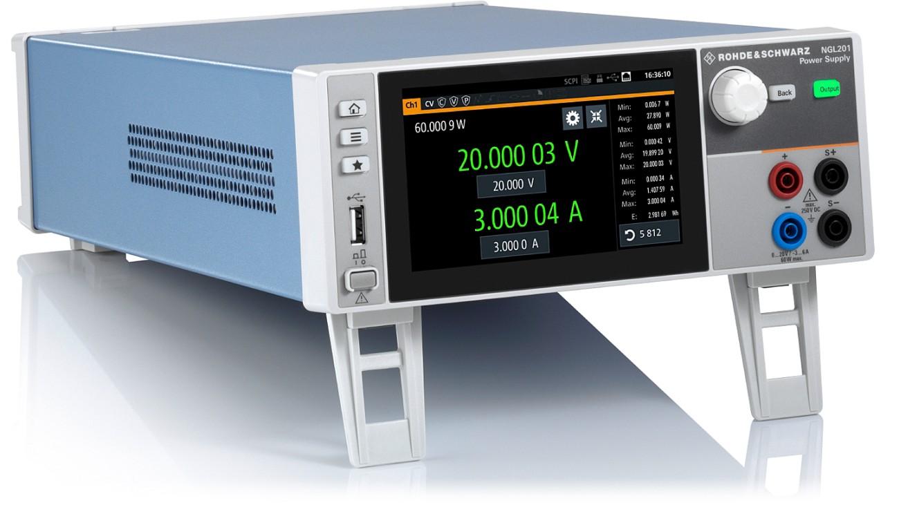
IoT and mobile communications are targeted by the R&S NGL200 power supplies from Rohde & Schwarz. The architecture allows them to function both as a source and a sink, while short recovery times of 30 microseconds enable them to handle fast load changes that occur, for example, when a device switches from sleep mode to transmit mode.
The single-channel R&S NGL201 and the two-channel R&S NGL202 deliver up to 60W of output power per channel. The output channels are floating, galvanically isolated and protected against overload and short circuits. The power supplies can sink power in a controlled manner, enabling them to simulate the specific characteristics of a battery. The optimised user interface is intuitive, and temperature-controlled fans ensure extremely quiet operation, confirms Rohde & Schwarz.
The linear two-quadrant design of the output stages enables the R&S NGL200 power supplies to operate as a source and sink, with automatic switching from source mode to sink mode.
Linear regulation delivers stable output voltages and currents, making them suitable for powering sensitive modules and for developing power amplifiers and MMICs.
With up to 6 ½ digit resolution for voltage, current and power measurements, the R&S NGL200 series can characterize devices that have low power consumption in standby mode and high current in full load operation. The entire measuring range is covered without having to switch ranges, speeding up measurements. In many cases, an additional digital multimeter is not necessary, advises Rohde & Schwarz. This saves space and money and simplifies test setups.
In addition to channel outputs, the R&S NGL200 series provides connectors for sense lines. USB and LAN interfaces are installed as standard for remote control. The R&S NGL-K102 option adds WLAN support. Digital inputs and outputs are available with the R&S NGL-K103 option, and the R&S NGL-B105 hardware option provides a GPIB (IEEE-488) interface.
The R&S NGL200 power supply series is available now from Rohde & Schwarz and selected distributors for prices starting at $2,190.
RFID is one of these technologies that change how we interact with other electronic devices and things in our environment. It is used in every application where some unique identifier is required, from retail to security and is also leading the path along several futuristic innovations with RFID based human implants among others. This wide range of applications makes RFID desirable and useful for several Arduino projects. For today’s tutorial, we will look on how to use RFID in Arduino based projects.
How it works
Before we dive into the project, it’s probably important to do an introduction on RFID. RFID stands for Radio Frequency Identification System. It comprises of two main parts; the reader (and ofteb writer) and the tags. The readers use electromagnetic field to automatically identify and track electronically stored, information contained in tags. Some of these readers also come with writing ability which enables them to change the information stored on compatible tags within their proximity.
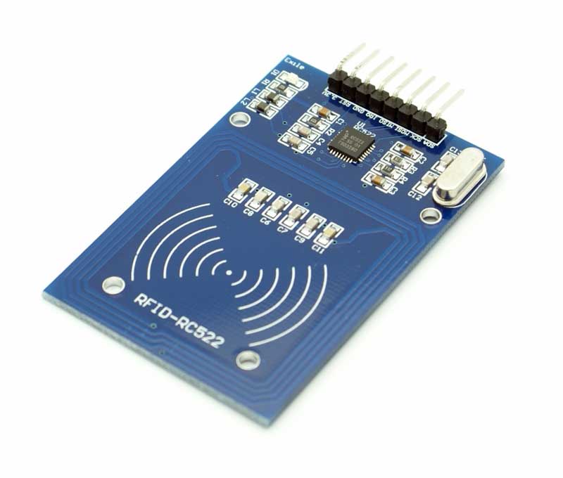
RC522 RFID reader
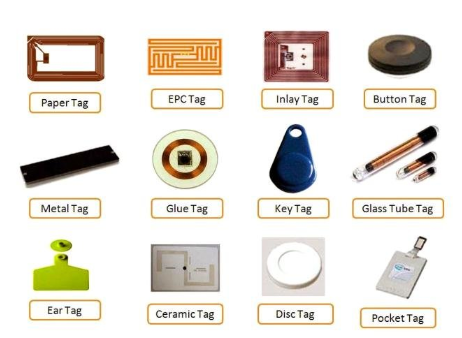
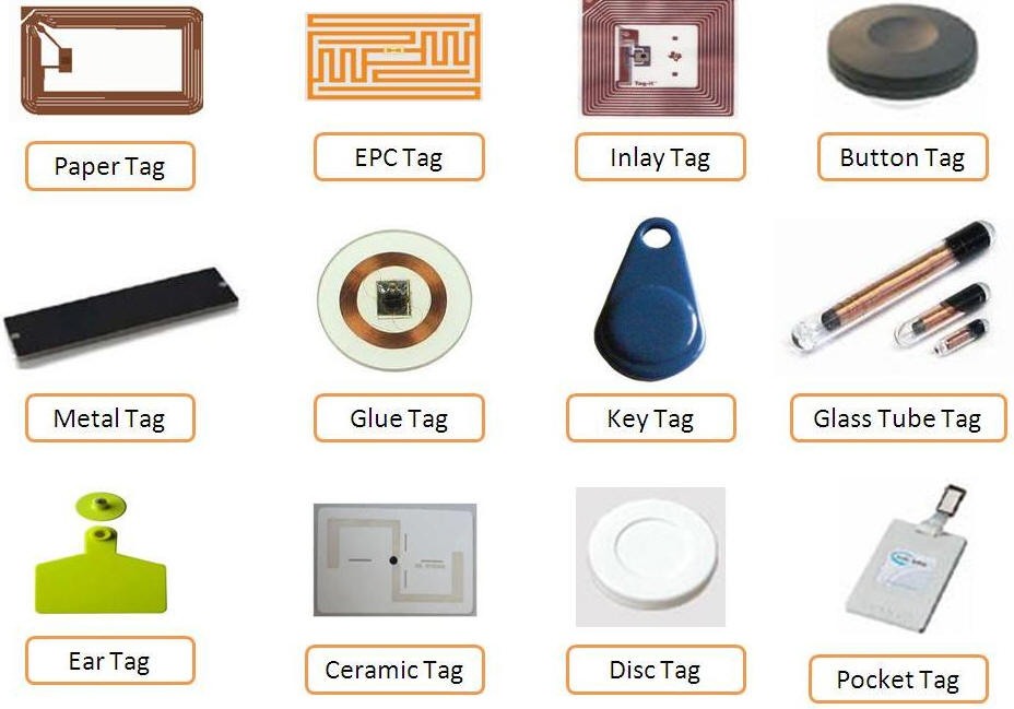
The tags, on the other hand, carry pre-stored information from writers and send this info to the reader when requested. Each RFID tag has a small chip inside, which can usually be seen if a flashlight is placed under the tag. All the information in the tag is stored on the chip, including a unique number (known as the UID) through which the tags are identified and differentiated from each other. RFID tags can either be passive or active. Passive tags are usually short range and have no power source embedded. They are powered via induction from the electromagnetic field of the reader when they are in range and information is transmitted to them. Active tags, however, are usually battery powered and are capable of communicating with readers over longer distances.
Different types of RFID tags. Image: avirajtech.com
For today’s tutorials, we will use the RC522 RFID reader to obtain the UID of tags placed near it and to create a simple prototype of an RFID based door lock system. The RC522 RFID reader is a low cost, highly integrated, 13.56 MHz contactless communication enabled reader module. It is by far one of the most popular RFID readers among hobbyists and makers due to its low cost and ease of use with the Arduino. Some of the features of the RFID reader are described below:
MFRC522 chip based board
Operating frequency: 13.56MHz
Supply Voltage: 3.3V
Current: 13-26mA
Read Range: Approx 3cm
SPI Interface
Max Data Transfer Rate: 10Mbit / s
Dimensions: 60mm × 39mm
At the end of this tutorial, you will know how to build RFID based Arduino projects.
Required Components
The following components are required to build this project:
As usual, this component can be purchased via the links attached to them.
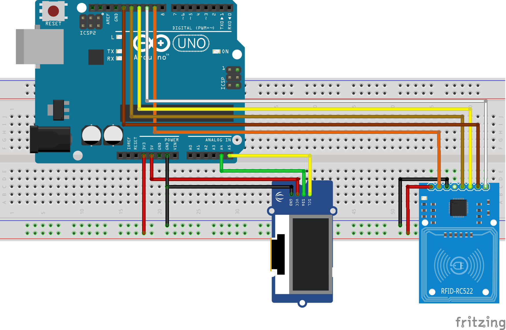
Schematics
The schematic for this project is quite simple. The RFID module uses the SPI communication protocol, so it will be connected to the dedicated SPI pins on the Arduino. The OLED display, on the other hand, uses I2C protocol and will thus also be connected to the Arduino’s dedicated I2C lines. Connect the component as shown in the schematics below.
Schematics
To make the schematics easier to follow, the pin connections between the Arduino and other components are described below.
The OLED display has been used in many tutorials on this website. You can check them out to learn more about using OLED displays.
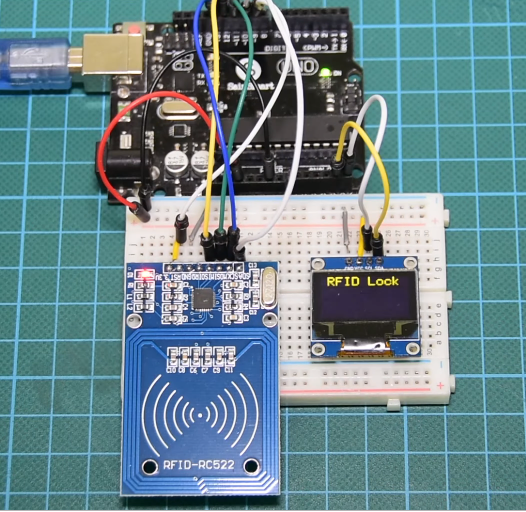
Go over your connections once again to be sure everything is as it should be. The final setup after the connections should look like the image below.
Components connected with Arduino
The RC522 module may be damaged if connected to a voltage above 3.3v so ensure it is rightly connected.
Code
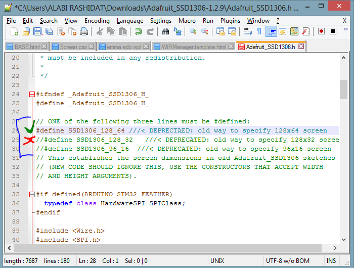
To simplify and reduce the amount of code needed for this project, we will use the MFRC522 library, the Adafruit SD1306, and the Adafruit GFX libraries. For everyone running the latest version of the Arduino IDE, you can download these libraries via the library manager. Go to “Sketch -> Include Libraries -> Manage libraries” and enter the name of the libraries into the search bar and install them one after the other. With the libraries installed, go to your libraries folder and open the Adafruit_SSD1306.h using any code editor like notepad++. We will change the default screen resolution to match that of our display (128×64) by commenting out the default value (128×32) and un-commenting the line that matches our display as shown in the image below.
Set SSD1306 display Resolution
With this done, save and relaunch the IDE. We are now ready for the code.
The code for this project is quite easy and as mentioned during the introduction, we will read tags and check if they match pre-stored UIDs. If there is a match, “unlocked” will be displayed on the OLED display and if there is no match, the OLED will display “locked”, simulating the actions on an RFID based door lock system.
As usual, I will do a quick break down of the code and try as much as possible to explain all the key parts of the code. We start by including the libraries that will use as discussed above.
//Written by Nick Koumaris
//info@educ8s.tv

#include <MFRC522.h>
#include <Adafruit_GFX.h>
#include <Adafruit_SSD1306.h>
#include <SPI.h>
Next, we create an instance of the SSD1306 library for the OLED display, declare the pins of the Arduino to which the reader is connected and create an instance of the MFRC522 library.
#define OLED_RESET 4
Adafruit_SSD1306 display(OLED_RESET);

#define SS_PIN 10
#define RST_PIN 9

MFRC522 rfid(SS_PIN, RST_PIN); // Instance of the class

MFRC522::MIFARE_Key key;
Next, we declare the UID (an array of integers) of the RFID tag, that we want the Arduino to recognize and other variables that will be used in the code.
int code[] = {69,141,8,136}; //This is the stored UID
int codeRead = 0;
String uidString;
Next, we write the void setup function where we initialize the RFID reader and the display. Serial, SPI and I2C communications are also initiated and we set the system to start in lock mode, waiting for tags to be scanned.
void setup() {

  Serial.begin(9600);
  SPI.begin(); // Init SPI bus
  rfid.PCD_Init(); // Init MFRC522

  display.begin(SSD1306_SWITCHCAPVCC, 0x3C);  // initialize with the I2C addr 0x3D (for the 128x64)

  // Clear the buffer.
  display.clearDisplay();
  display.display();
  display.setTextColor(WHITE); // or BLACK);
  display.setTextSize(2);
  display.setCursor(10,0);
  display.print("RFID Lock");
  display.display();

}
Next, is the void loop() function. The loop function simply calls the readrfid function whenever the RFID reader detects an RFID card with a delay of 100ms between calls to allow the information from the tags to be processed.
The readrfid function does all the heavy lifting associated with this project. The function is quite long but, it simply extracts the UID of the tag being scanned and checks if it matches the stored UID. If there is a match, the unlock message is printed, while if there is not a match, the system stays locked.
void readRFID()
{
rfid.PICC_ReadCardSerial();
Serial.print(F("\nPICC type: "));
MFRC522::PICC_Type piccType = rfid.PICC_GetType(rfid.uid.sak);
Serial.println(rfid.PICC_GetTypeName(piccType));
// Check is the PICC of Classic MIFARE type
if (piccType != MFRC522::PICC_TYPE_MIFARE_MINI &&
piccType != MFRC522::PICC_TYPE_MIFARE_1K &&
piccType != MFRC522::PICC_TYPE_MIFARE_4K) {
Serial.println(F("Your tag is not of type MIFARE Classic."));
return;
}
clearUID();
Serial.println("Scanned PICC's UID:");
printDec(rfid.uid.uidByte, rfid.uid.size);
uidString = String(rfid.uid.uidByte[0])+" "+String(rfid.uid.uidByte[1])+" "+String(rfid.uid.uidByte[2])+ " "+String(rfid.uid.uidByte[3]);
printUID();
int i = 0;
boolean match = true;
while(i<rfid.uid.size)
{
if(!(rfid.uid.uidByte[i] == code[i]))
{
match = false;
}
i++;
}
if(match)
{
Serial.println("\nI know this card!");
printUnlockMessage();
}else
{
Serial.println("\nUnknown Card");
}
// Halt PICC
rfid.PICC_HaltA();
// Stop encryption on PCD
rfid.PCD_StopCrypto1();
}
other functions used include the printUID() function and the printunlockmessage() function which should be easy to follow.
The complete code for the project is shown below.
//Written by Nick Koumaris
//info@educ8s.tv
#include <MFRC522.h>
#include <Adafruit_GFX.h>
#include <Adafruit_SSD1306.h>
#include <SPI.h>
#define OLED_RESET 4
Adafruit_SSD1306 display(OLED_RESET);
#define SS_PIN 10
#define RST_PIN 9
MFRC522 rfid(SS_PIN, RST_PIN); // Instance of the class
MFRC522::MIFARE_Key key;
int code[] = {69,141,8,136}; //This is the stored UID
int codeRead = 0;
String uidString;
void setup() {
Serial.begin(9600);
SPI.begin(); // Init SPI bus
rfid.PCD_Init(); // Init MFRC522
display.begin(SSD1306_SWITCHCAPVCC, 0x3C); // initialize with the I2C addr 0x3D (for the 128x64)
// Clear the buffer.
display.clearDisplay();
display.display();
display.setTextColor(WHITE); // or BLACK);
display.setTextSize(2);
display.setCursor(10,0);
display.print("RFID Lock");
display.display();
}
void loop() {
  if(  rfid.PICC_IsNewCardPresent())
  {
      readRFID();
  }
  delay(100);

}
void readRFID()
{

  rfid.PICC_ReadCardSerial();
  Serial.print(F("\nPICC type: "));
  MFRC522::PICC_Type piccType = rfid.PICC_GetType(rfid.uid.sak);
  Serial.println(rfid.PICC_GetTypeName(piccType));

  // Check is the PICC of Classic MIFARE type
  if (piccType != MFRC522::PICC_TYPE_MIFARE_MINI &&
    piccType != MFRC522::PICC_TYPE_MIFARE_1K &&
    piccType != MFRC522::PICC_TYPE_MIFARE_4K) {
    Serial.println(F("Your tag is not of type MIFARE Classic."));
    return;
  }

    clearUID();

    Serial.println("Scanned PICC's UID:");
    printDec(rfid.uid.uidByte, rfid.uid.size);

    uidString = String(rfid.uid.uidByte[0])+" "+String(rfid.uid.uidByte[1])+" "+String(rfid.uid.uidByte[2])+ " "+String(rfid.uid.uidByte[3]);

    printUID();

    int i = 0;
    boolean match = true;
    while(i<rfid.uid.size)
    {
      if(!(rfid.uid.uidByte[i] == code[i]))
      {
           match = false;
      }
      i++;
    }

    if(match)
    {
      Serial.println("\nI know this card!");
      printUnlockMessage();
    }else
    {
      Serial.println("\nUnknown Card");
    }


    // Halt PICC
  rfid.PICC_HaltA();

  // Stop encryption on PCD
  rfid.PCD_StopCrypto1();
}
void printDec(byte *buffer, byte bufferSize) {
for (byte i = 0; i < bufferSize; i++) {
Serial.print(buffer[i] < 0x10 ? " 0" : " ");
Serial.print(buffer[i], DEC);
}
}
void clearUID()
{
display.setTextColor(BLACK); // or BLACK);
display.setTextSize(1);
display.setCursor(30,20);
display.print(uidString);
display.display();
}
void printUID()
{
display.setTextColor(WHITE); // or BLACK);
display.setTextSize(1);
display.setCursor(0,20);
display.print("UID: ");
display.setCursor(30,20);
display.print(uidString);
display.display();
}
void printUnlockMessage()
{
display.display();
display.setTextColor(BLACK); // or BLACK);
display.setTextSize(2);
display.setCursor(10,0);
display.print("RFID Lock");
display.display();
display.setTextColor(WHITE); // or BLACK);
display.setTextSize(2);
display.setCursor(10,0);
display.print("Unlocked");
display.display();
delay(2000);
display.setTextColor(BLACK); // or BLACK);
display.setTextSize(2);
display.setCursor(10,0);
display.print("Unlocked");
display.setTextColor(WHITE); // or BLACK);
display.setTextSize(2);
display.setCursor(10,0);
display.print("RFID Lock");
display.display();
}
Demo
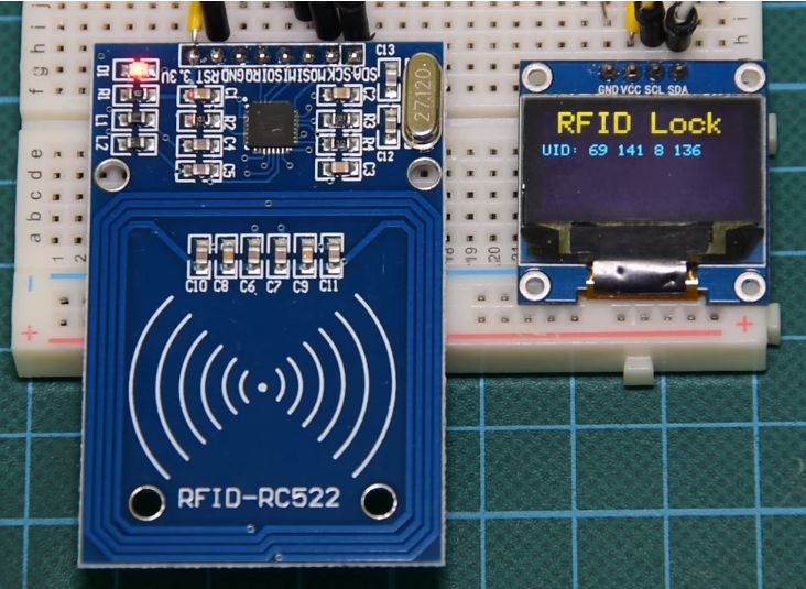
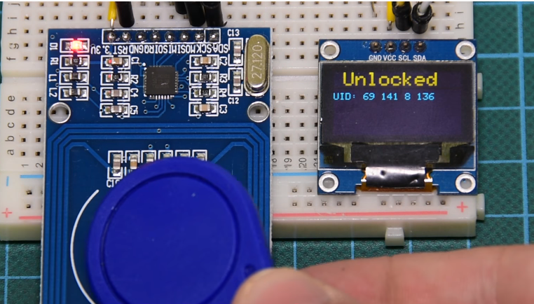
Go over the schematics and ensure the components are properly connected, then upload the code to the Arduino board. Ensure the libraries have been installed as described and the modifications to the SD1306 library has been made as described. After Uploading, you should see the OLED come up as shown below.
Put the card with the known UID across the RFID reader and you should see the screen indicate “Unlocked”. After a few minutes, It will go back to “locked” and you can then scan an unknown tag and see the outcome.
Demo
That’s it for this tutorial guys. As simple as it may seem, RFIDs have applications in diverse industries from security to retail and the example we just built, could serve as building block for an RFID based door lock system or a retail solution. What RFID application are you most interested in? do share via the comment section along with questions and other comments.
Till Next time!
The video version of this tutorial is available on youtube.