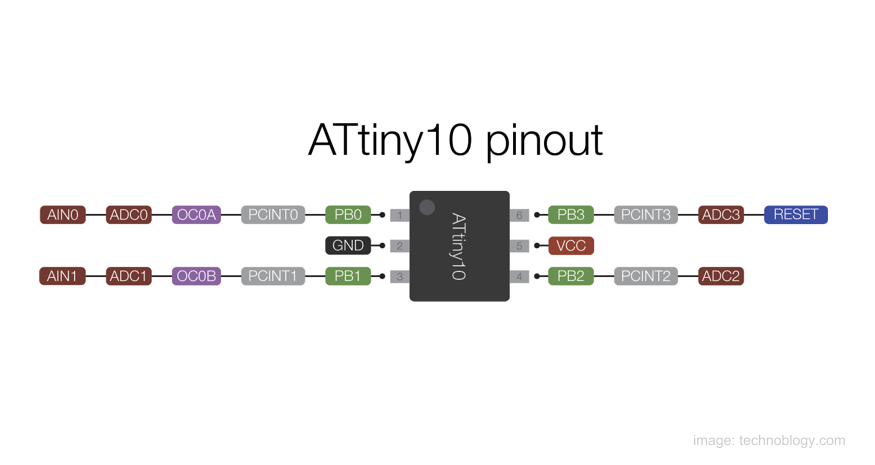
Here is a nice video from Ben Heck describing how to program and use the smallest AVR microcontroller, the ATTINY10. He covers, how to wire a small converter and an AVR High Voltage Programmer, how to get started with Atmel Studio 7 and basic I/O, how to blink a LED and view the signal with an oscilloscope, how to use interrupts to bit-bang a serial protocol to get data out of the device and how to use the ADC to get readings from attached sensors. This video can be considered as a introduction tutorial on ATTINY10 and the details covered will get you started with this tiny mcu. The video is almost 50min long, so take your seat and enjoy.
ATTINY10 cannot be programmer using the standard AVR ISP programming interface but instead it uses TPI interface which requires 12V programming. Some great resources on programming this microcontroller are listed below.
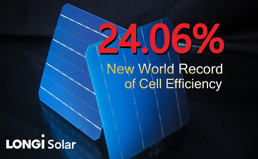
LONGi Solar has announced that it has achieved a new monocrystalline silicon PERC (Passivated Emitter Rear Cell) world record conversion efficiency using commercial wafer (M2) dimensions that exceeds 24 percent for the first time, according to tests carried out by the National Center of Supervision and Inspection on Solar Photovoltaic Product Quality (CPVT) in China.
LONGi Solar’s latest breakthrough bifacial (double-sided) PERC solar cells tested by CPVT achieved a conversion efficiency of 24.06 percent. LONGi Solar had previously reported verified record PERC cell conversion efficiencies of 23.6 percent in February 2018.
CPVT tested monocrystalline silicon PERC cell in standard wafer dimension (156.75×156.75mm2) (M2) provided by LONGi Solar. The sample cells were measured under standard test conditions for current-voltage characteristics as a function of load.
LONGi Solar has made great strides in setting world record PERC solar cell conversion efficiencies as we demonstrate the continuing ability to provide high-efficiency products to the global solar market,” stated Li Wenxue, President of LONGi Solar. “Our latest record solar cell conversion efficiencies also endorse the success of our R&D investments, which have set the benchmark for the industry in recent years.
In April 2017, based on selective emitter technology, which has been widely used in practical mass production, LONGi Solar reported a monocrystalline silicon PERC cell conversion efficiency of 22.17 percent (tested by CPVT), which effectively supported the supply requirements of the Phase 3 requirements of China’s ‘Top Runner’ solar installation program.
In October 2017, LONGi Solar broke the world-record efficiency of monocrystalline silicon PERC cell in commercial dimensions with 22.71%, while the original record was broken by Fraunhofer-ISE with 22.61 percent. In the same month, in accordance with the MBB (Multi Busbar) technology, the cell conversion efficiency was increased to 23.26 percent and tested by CPVT, which was the first to breakthrough the 23 percent efficiency barrier.
The FBH and Technische Universitaet Berlin (TU Berlin) spin-off from Germany develops and manufactures LEDs emitting in the UVB (280 nm – 320 nm) and the UVC (230 nm – 280 nm) spectral regions . Due to their customizable wavelengths , low operation voltages, ability to be rapidly switched and dimmed along with their robustness , the compact devices are suited for a great variety of applications. These include water purification, disinfection, medical diagnostics, phototherapy, plant growth, UV curing, and sensing.
Featured products at Photonics West 2019 comprise 310nm – UVB LEDs with up to 30mW out put power at 350mA and 265 nm UVC LEDs with > 25 mW at 350 mA. Also, fully packaged UVC LEDs with single emission peak at 233nm and an output power of 0.3mW at 100mA will be showcased. In addition to these standard wavelengths, UVphotonics offers customizable LEDs tailoring the emission wavelength, emission area and spatial emission characteristics to meet to the specific requirements of the respective application.
We stay at the forefront of UV LED technology due to our close collaboration with the FBH and the TU Berlin ”, points out Dr. Neysha LoboPloch, CEO of UVphotonics.
The FBH conducts R&D on (Ga,Al,In)N UV LEDs and performs all stages of device fabrication in-house, from design to epitaxial growth to chip processing , packaging and up to complete turn-key modules which are ready to use in applications
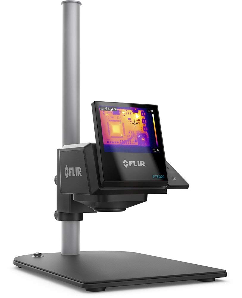
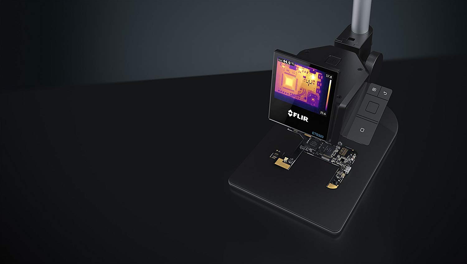
The FLIR ETS320 is the first true electronic test bench camera, designed for Quick temperature checks on PCB boards and electronic devices. The FLIR ETS320 is sensitive enough to detect subtle temperature differences with an accuracy of ±3°c, so you can quickly find hot spots and potential points of failure. The 320 × 240 infrared detector offers more than 76 000 points of temperature measurement, eliminating the guesswork of legacy measurement tools. Designed specifically for bench-top work, the battery-powered FLIR ETS320 connects to your pc for immediate analysis and sharing of thermal data. Product comes with camera, mount, stand, power supply, USB cable, and FLIR tools+ software.
Specifications
320 x 240 IR resolution (76,800 pixels)
Object Temperature Range -20°C to 250°C (-4°F to 482°F)
Vibrant 3” LCD display
45° field of view
±3% measurement accuracy
Records standard radiometric JPEGs
FLIR Tools+ software provided
ensitive enough to detect temperature differences smaller than 0.06°C, for fast identification of faults and thermal gradients.
Measurement accuracy of 2°c aids in attaining quality assurance and factory acceptance of printed circuit boards.
Ergonomically designed for lab electronics measurement, the ETS320 is battery powered, Wireless, and hands free.
With complete measurement and analysis on the camera, the ETS320 measures small components down to 150 µm per pixel spot size, from a minimum focus distance of 70mm.
Overview Video
More information on FLIR and on Datasheet. Price for FLIR ETS320 thermal camera is $2,499 and is available on amazon.com
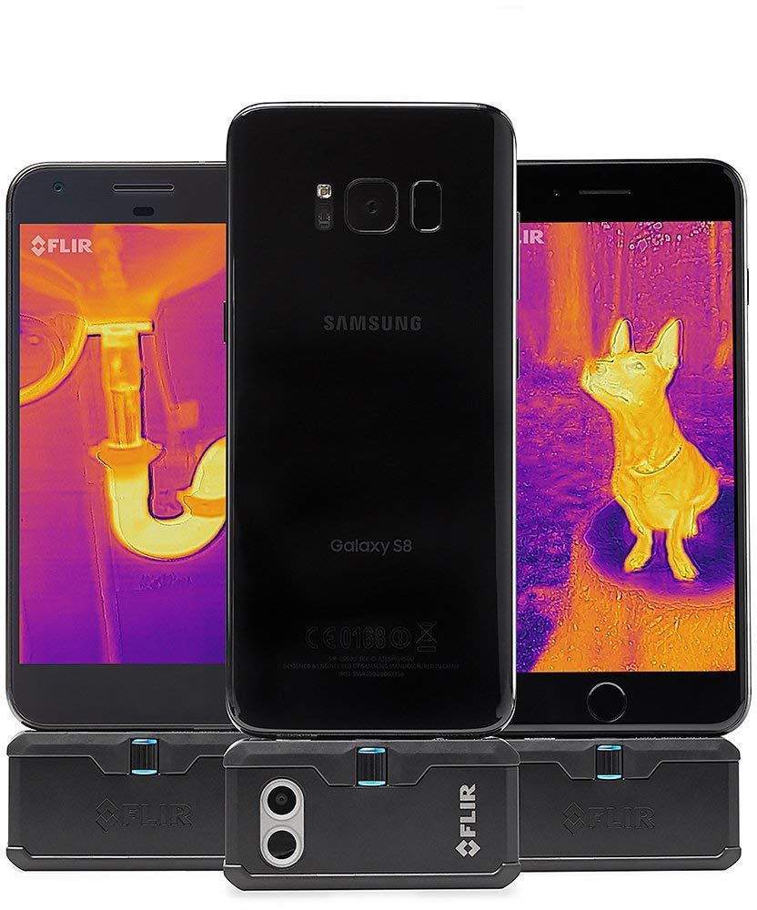
FLIR One Pro LT thermal camera smartphone attachment
An alternative and cheaper solution to thermal imaging is the FLIR ONE PRO LT Thermal Imaging Camera attachment for smartphones.
The all new FLIR One Pro LT gives you the power to find invisible problems faster than ever. Simply attach the FLIR ONE PRO LT to a supported Android phone/tablet with micro USB connector, and turn it into a powerful thermal imager with 4, 800 (80 x 60) resolution. With class-leading MSX technology that overlays visual image details into the thermal image plus VividIR image processing, the FLIR ONE PRO LT lets you see more details and get visual proof that you solved the problem right the first time. Whether you’re inspecting homes, cars, electrical panels, looking for HVAC problems, finding water damage, or having fun in the outdoors, the new FLIR ONE PRO LT is a tool No serious professional should be without.
Specifications
Non-Operating Temperature -20°C — 60°C (-4°F — 140°F)
Scene Dynamic Range -20°C — 120°C (-4°F — 248°F)
Spot Meter Off / °C / °F. R
Resolution 0.1°C / 0.1°F
Thermal Sensitivity/NETD 100 mK
Weight 36.5 g
Dimensions (H x W x D) 68 × 34 × 14 mm (2.7 × 1.3 × 0.6 in)
Phone iOS
Unboxing Video
More information on FLIR website. FLIR ONE PRO LT costs $299.99 and is available on amazon.com
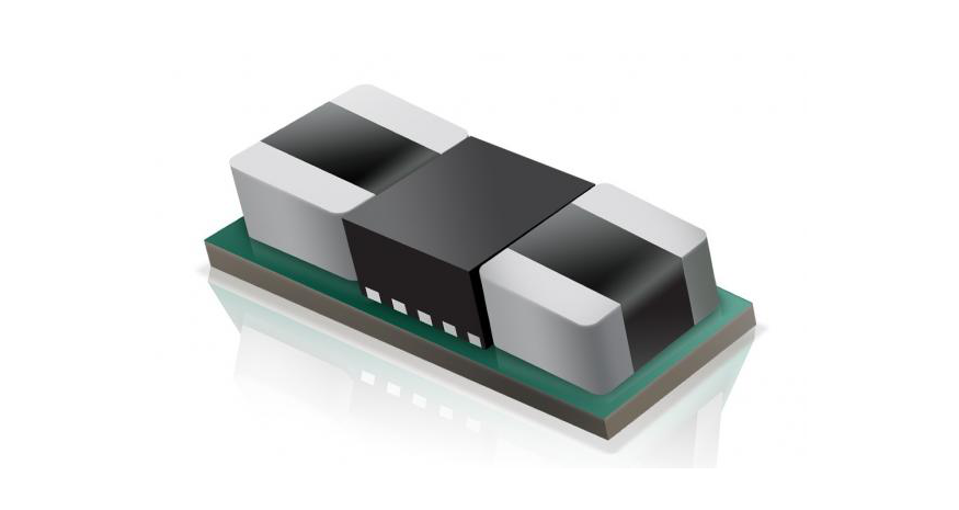
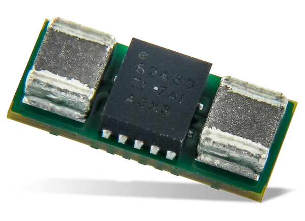
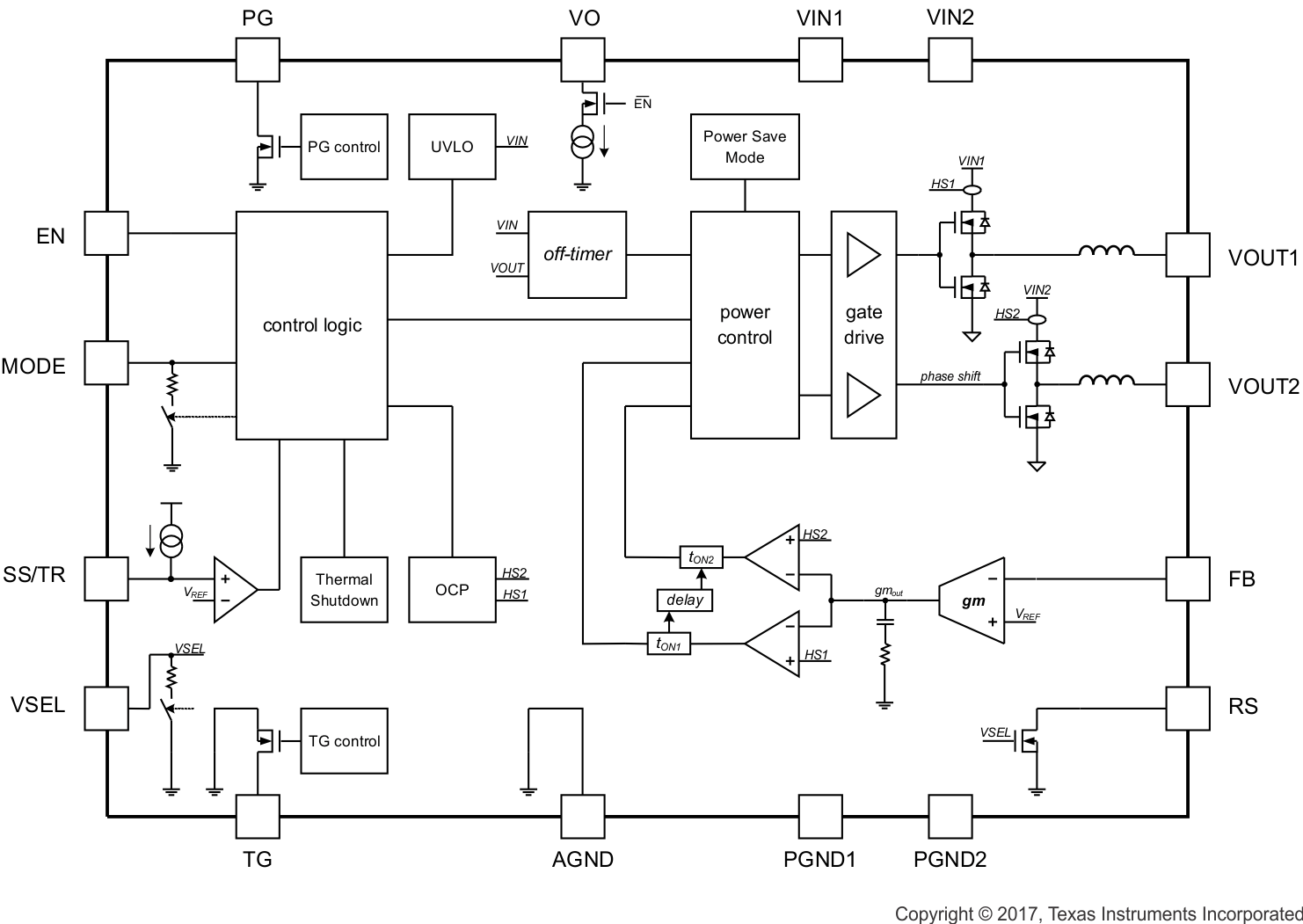
The TPSM82480 is a synchronous step-down DC-DC converter module for low profile point-of-load power supplies. The input voltage range of 2.4 to 5.5 V enables operation from typical 3.3-V or 5-V interface supplies as well as from backup circuits dropping down as low as 2.4 V.
The output current is up to 6 A continuously provided by two phases of 3 A each, which run out-of-phase, reducing pulse current noise significantly.
photo of TPSM82480 step-down module
The TPSM82480 provides an automatically entered power save mode to maintain high efficiency down to very light loads. This incorporates an automatic phase adding and shedding feature using both or only one phase according to the actual load. The power save mode can be switched off using the MODE feature.
The device offers a Power Good signal and an adjustable soft start. Also, the device features a Thermal Good signal to indicate excessive internal temperature. The output voltage can be changed to a preselected value by VSEL pin. TPSM82480 is able to operate in 100% duty cycle mode.
Block Diagram
Features
Ultra Small 7.9 x 3.6 x 1.5 mm Power Module
Output Current of 6 A
Feedback Voltage Accuracy of ±1%
Input Voltage Range 2.4 to 5.5 V
Output Voltage Range 0.6 to 5.5 V
Typical Quiescent Current of 23 µA
Output Voltage Select
Phase Shifted Operation
Automatic Power Save Modes
Forced PWM Mode Option
Adjustable Soft Start
Power Good & Thermal Good Outputs
Undervoltage Lockout
Over-current and Short-Circuit Protection
Over-temperature Protection
-40°C to 125°C Operating Temperature Range
Prices start from $3.1 @ 1000 units in QFM package. More information on: www.ti.com
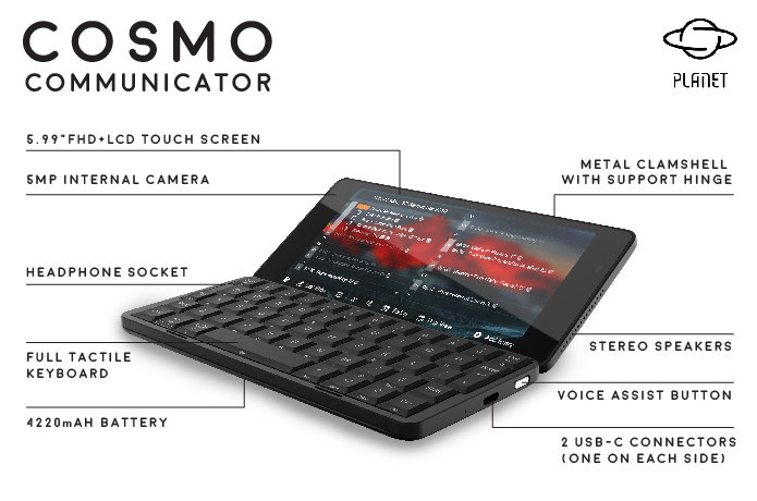
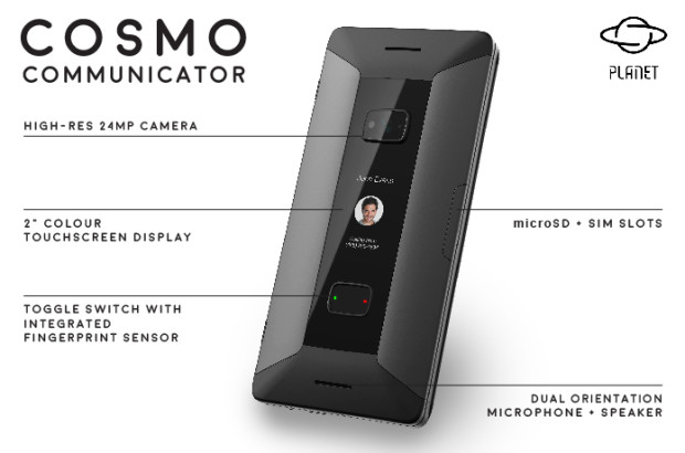
Planet Computers has launched Cosmo Communicator, a dual-screen clamshell-based mobile communicator. It is built to serve as a pocket computer, a mobile phone, and a high-resolution camera. The Cosmo has dual color displays. One 2″ display serves as an external color touchscreen for easy phone call control and notifications, while the other is inside. The inside display is an ultra-wide 6” colour touchscreen along with a full functioning keyboard embedded into the device. When opened, the clamshell serves as a support base to the device, allowing the user to type conveniently. The backlit keyboard enables the user to easily work at night or in dark spaces without the need for external lighting.
Cosmo Communicator major features
The Cosmo Communicator is equipped with a 24MP camera (zoom and flash supported) which you can operate without opening the clamshell. The Cosmos supports 4G LTE phone modem to enable dual 4G SIM connections, for both phone calls and data. It also features Bluetooth, NFC and Wi-Fi communications. Cosmo’s toggle switch enables high security for the device with an incorporated fingerprint sensor and call answer buttons, so you can avoid accepting calls accidentally when the device is in your pocket or handbag. The Cosmo is based on MediaTek P708-core processor plus separate GPU and AI processors. It is equipped with a 6GB RAM and 128 GB Flash memory. MicroSD expansion memory slot is also available.
The device is equipped with a 4220 mAh battery, which provides enough power for a day or even two days of usage. The Cosmo enables their users to work in restricted spaces comfortably. You can also hold the Cosmo and use it with ease standing up or while on the bus. It’s size is small enough to fit in your pocket and it can serve as a replacement for both your mobile phones and your laptop. Cosmos was launched in September in an Indiegogo campaign and although campaign is finished it is still available for purchase as an in-demand product 596 + plus shipping. Delivery is scheduled for May / June 2019. Retail price is expected to be $799.
Overview Video
Cosmo Communicator preliminary specifications:
SoC – Mediatek P70 octa-core processor with four Arm Cortex A73 cores @ up to 2.0GHz, four Cortex A53 cores @ up to 2.0GHz, Arm Mali G72 MP3 GPU @ 800MHz, and a Dual-core mobile AI processor (APU)
System Memory – 6GB RAM
Storage – 128GB flash, microSD card slot
Displays
Main Display – 5.99″ touchscreen display with 2160×1080 resolution (FHD+ 18:9), scratch resistant glass
External Display – 2.0″color AMOLED touchscreen display with 570 x 240 resolution, scratch-resistant glass
Cypress Semiconductor Serial F-RAM (ferroelectric RAM) memories combine the nonvolatile data storage capability of ROM with the fast speeds of RAM. Serial F-RAM features a variety of interface and density options, including SPI and I2C interfaces, industry-standard packages, and densities ranging from 4KB to 4MB. Cypress Serial F-RAMs have three distinct advantages over other nonvolatile memory technologies: fast write speed, extremely high endurance, and low power consumption. Serial F-RAMs provide 100 trillion cycle endurance, exceeding the 1 million write cycle limitation of EEPROM. This eliminates the need for wear leveling to support a product over its lifespan.
F-RAM provides fast writes at full interface speed. F-RAM does not have any write delays and data is instantly nonvolatile. Traditional nonvolatile memories have delays of 5 or more milliseconds before data becomes nonvolatile. If power is disrupted, pending data is lost unless the system has extra capacitance or batteries to keep the system on until data is stored.
F-RAM offers virtually unlimited endurance of 100 trillion read/write cycles. Traditional nonvolatile memories typically have less than 1 million cycle endurance, forcing system designers to use complex wear-leveling routines and up to 4x more density to prolong the lifetime of these memories.
F-RAM consumes as low as 300 µA active and 6 µA standby current. Because of fast write speeds, F-RAM stays active for short periods of time, yielding very low energy consumption. Traditional nonvolatile memories with write delays must stay active for longer periods of time, resulting in higher energy consumption.
Serial F-RAM offers a pin-to-pin and footprint compatible EEPROM replacement.
The devices are made of a ferroelectric material that is highly resistant to influence by radiation and magnetic field exposure. This provides soft error rate immunity for a superior alternative to MRAM. These F-RAM devices are typically used in mission-critical applications. This includes smart meters, automotive electronics, industrial control, and automation equipment, multifunction printers and portable medical devices.
Cypress F-RAM Key Features
4Kb to 4Mb densities
Serial QSPI, DSPI, SPI and I2C interface options
Parallel interface options
Low power, instant data capture on power loss
100-trillion read/write cycle endurance
No batteries required to store data on power loss; RoHS compliant
Radiation and magnetic field tolerant
Processor Companions with integrated analog and digital functions
F-RAM Technology
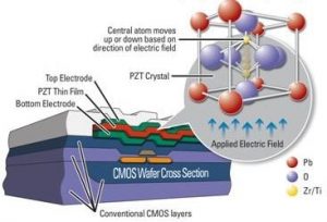
Cypress F-RAM is built on Ferroelectric technology. The F-RAM chip contains a thin ferroelectric film of lead zirconate titanate, commonly referred to as PZT. The atoms in the PZT change polarity in an electric field, thereby producing a power efficient binary switch. However, the most important aspect of the PZT is that it is not affected by power disruption, making F-RAM a reliable nonvolatile memory. A common misconception is that ferroelectric crystals are ferromagnetic or have similar magnetic properties. In fact, ferroelectric materials switch in an electric field and are not affected by magnetic fields.
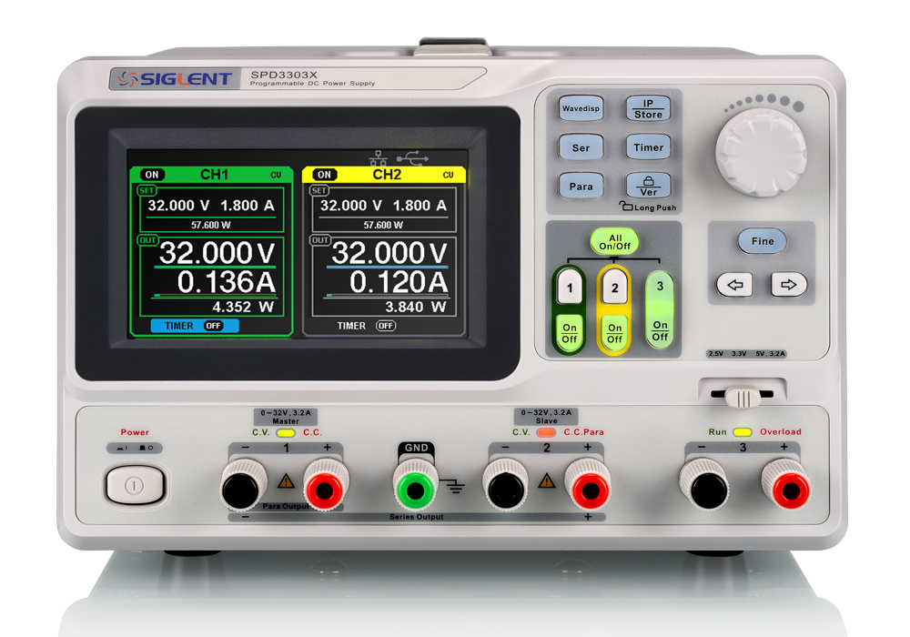
Siglent’s SPD3000X Series Programmable Linear DC Power Supply has a 4.3 inch TFT-LCD display, supports Remote Programming and has a Real Time Wave Display. The ‘3000X family has three isolated outputs; two adjustable channels and one selectable channel from 2.5v, 3.3V, and 5V. It also has output short and overload protection and can be used in production and development.
Key Features
3 independently controlled and isolated outputs: 32V/3.2A×2, 2.5V/3.3V/5V/3.2A×1, total 220W
Clear graphical interface, with waveform display function
Five internal groups of system parameter save/recall, supports data storage space expansion
Provides PC software; Easypower, supports SCPI, LabView drive
Characteristics
High-resolution / high-precision output
The highest resolution of 1mV/1mA (SPD3303X), provides excellent setting and read back accuracy. This ensures accurate output even with very with small changes in voltage or current. This is impossible with a low resolution power supply.
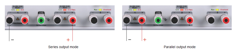
Series/parallel/independent mode functions
Series and parallel functions allows for combining two channels into one output with more power output capability, extending the application range. Each of 3 channels power can be turned on or off independently and also can be turned all on or all off.
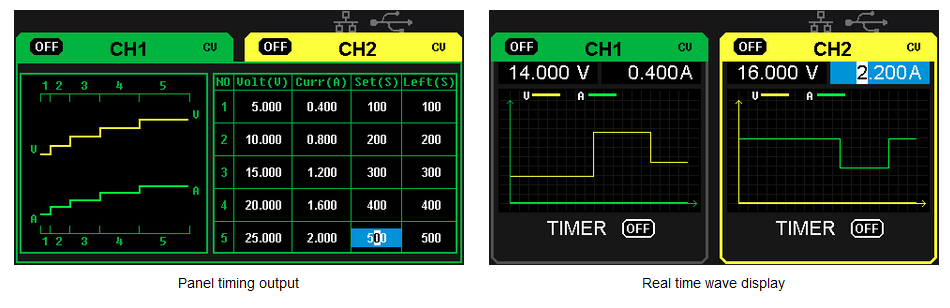
Panel displays the timing output
Through front panel operation, five groups of timing settings and output control can be displayed, which provides users with simple power programming functionality. Also, by connection to Siglent’s EasyPower PC software, a full range of communication and control features can be used.
Save/Recall setting parameters
The SPD3000X series programmable power supply can save or recall 5 groups of setting parameters in internal storage and also supports external storage expansion. Settings can be easily recalled if needed.
Overview Video
Siglent Technologies SPD3303X-E Triple Output Power Supply cost ~$389 on amazon.com
GPS technology plays an important role in our everyday life. From easy human navigation to navigation of aircraft, it helps solving different location-related problems. However, aside from providing location details, the NMEA data obtained from satellites by GPS modules also carry information for other parameters like altitude, pressure, date and time etc. The implication of this is that GPS modules can be used also in projects where these other parameters are needed.
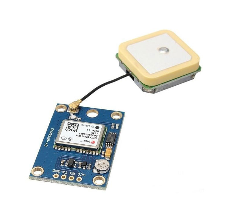
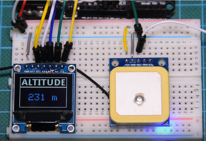
For today’s tutorial, we will use the UBLOX NEO-6M GPS module to determine the altitude of our place. A good application for this project would be a drone setup where the altitude is required as feedback to the IMU or other similar scenarios. While diverse kind of Arduino compatible GPS modules exists, they are often bulky and come with other constraints like high power requirements which put limitations on the project in which they can be used. This is where the UBLOX NEO 6M GPS Module comes in.
The module is compact and about the same size of small Arduino boards and this enable them to be easily fitted into any small Arduino project. The NEO-6M GPS module is a high-performing GPS receiver with a built-in 25 x 25 x 4mm ceramic antenna, which equips the module with a strong satellite search capability. The module communicates with connected microcontroller via serial protocol and operates on a voltage level between 3-5V.
We will use the GPS module to obtain altitude data and display them on an OLED display. At the end of the tutorial, you would know how to obtain diverse kind of information from a GPS module using NMEA protocol.
Required components
The following components are required to build this project;
As usual, all the components listed above can be bought via the links attached to them. It is also important to note that, the power bank is only needed for those who may want to test the project, in standalone mode.
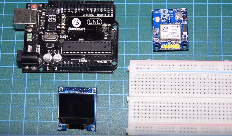
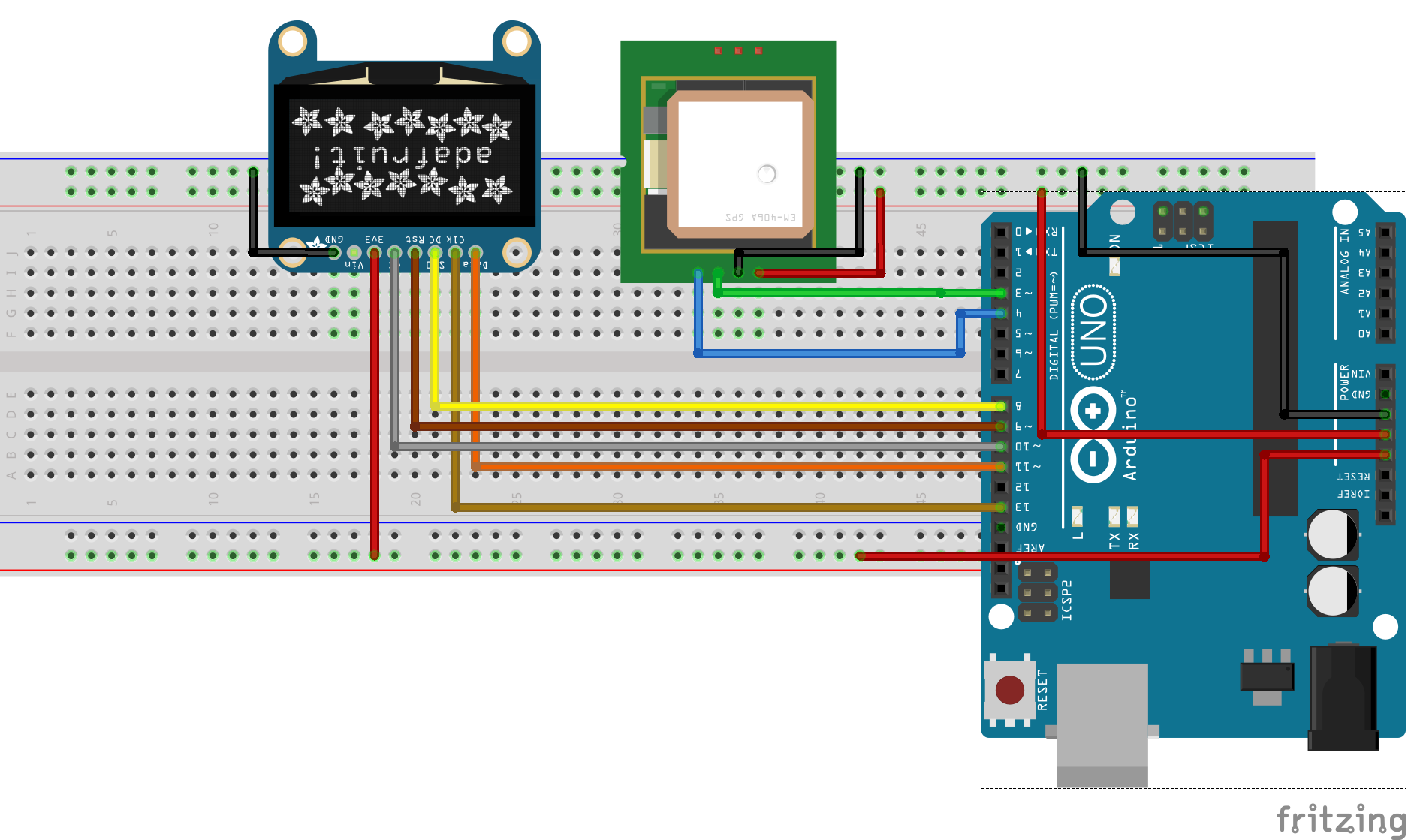
Schematics
The schematic for this project is fairly simple. Asides the Arduino, we have two other major components, the GPS Module and the OLED display. The GPS module communicates over serial so it will be connected to serial pins of the Arduino. However, we will use software serial-based communication to avoid interference on the hardware serial line, since it is what the Arduino uses to communicate with the PC.
Connect the components as shown in the schematics below.
Schematics
To make the connections easier to follow, a pin map showing how each of the components connects to the Arduino is shown below.
Go over the connections once again to be sure everything is as it should be.
Code
As mentioned earlier, we will use the GPS module not to obtain location information, like longitude and latitude, but to show how other parameters like altitude can be derived from the GPS output.
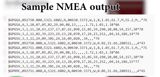
GPS modules as soon as they connect to satellites they pull a bunch of information which are referred to as NMEA data. This data contains useful information like location, altitude, pressure etc. Typical NMEA data are shown in the image below.
NMEA Data
Making sense of this information and extracting the needed data can be quite a task. To make things easy for us, we will use the tinyGPS++ library which already has all the functions required to extract specific information from the NMEA data. The Library can be downloaded via the link attached. In addition to tinyGPS++ library, we will use the Adafruit GFX library. The GFX library will make it easy to interact with the OLED display.
To do a quick breakdown of the code, as usual, we will start by including the libraries required for the project after which we define the pins of the Arduino to which the OLED is connected.
// writtern by Nick Koumaris
//Info@educ8s.tv

#include <SoftwareSerial.h>
#include <Adafruit_GFX.h>
#include <Adafruit_SSD1331.h>
#include <SPI.h>
#include "TinyGPS++.h"

#define sclk 13
#define mosi 11
#define cs   10
#define rst  9
#define dc
Next we specify the variables to represent the hex number of the colors to be used by the project and also create an instance of the tinyGPS++ library. This instance will be used to refer to the module which pass through the code.
#define  BLACK           0x0000
#define BLUE            0x001F
#define RED             0xF800
#define GREEN           0x07E0
#define CYAN            0x07FF
#define MAGENTA         0xF81F
#define YELLOW          0xFFE0
#define WHITE           0xFFFF

TinyGPSPlus gps;
To make the data display more user friendly, a splach screen and icons were created so the information can be displayed in a neat and cool way. The char code representing the UI and the icons are declared below. To learn how to generate your own code to encode an image, you can check past tutorials.
Next, we initialize the software serial library stating with the pins of the arduino to be used as the software TX and RX pins. We also create an instance of the OLED Library and move from there to the void setup() function.
Under the void setup() function, we initialize the display and serial communications declaring the baud rate at which we want the devices to communicate. The preset baud rate for the particular GPS module used for this project is 9600bps. Ensure it is the same for your module or modify accordingly. To round things off, we display the UI, getting the OLED ready to display altitude data. Next is the void loop() function.
void setup()
{

  display.begin();
  display.fillScreen(BLACK);

  printSplashScreen();

  SoftSerial.begin(9600);  // the SoftSerial baud rate
  delay(1000);
  Serial.begin(9600);      // the Serial port of Arduino baud rate.
  delay(2000);
  printUI();

}
Under the void loop function, we check if data is being received by the GPS module and we use the gps.altitude.meters() function to extract altitude information from the module. The code also shows examples of how location information, can be obtained from the NMEA data, using the gps.location.lat() and the gps.location.lng() functions to get longitude and latitude information.
The demo for this project is quite simple. Go over the schematics to confirm you have everything hooked-up correctly then upload the code to your Arduino board. After a few minutes you should see the altitude of the device’s current location being displayed on the OLED. Be sure to test the module outdoors and with a view to the sky.
Demo
That’s it for this tutorial guys. Thanks for going through it to the end. If you have questions around today’s tutorial, feel free to reach out to me via the comment section.
Till Next time!
The video version of this tutorial is available on youtube.
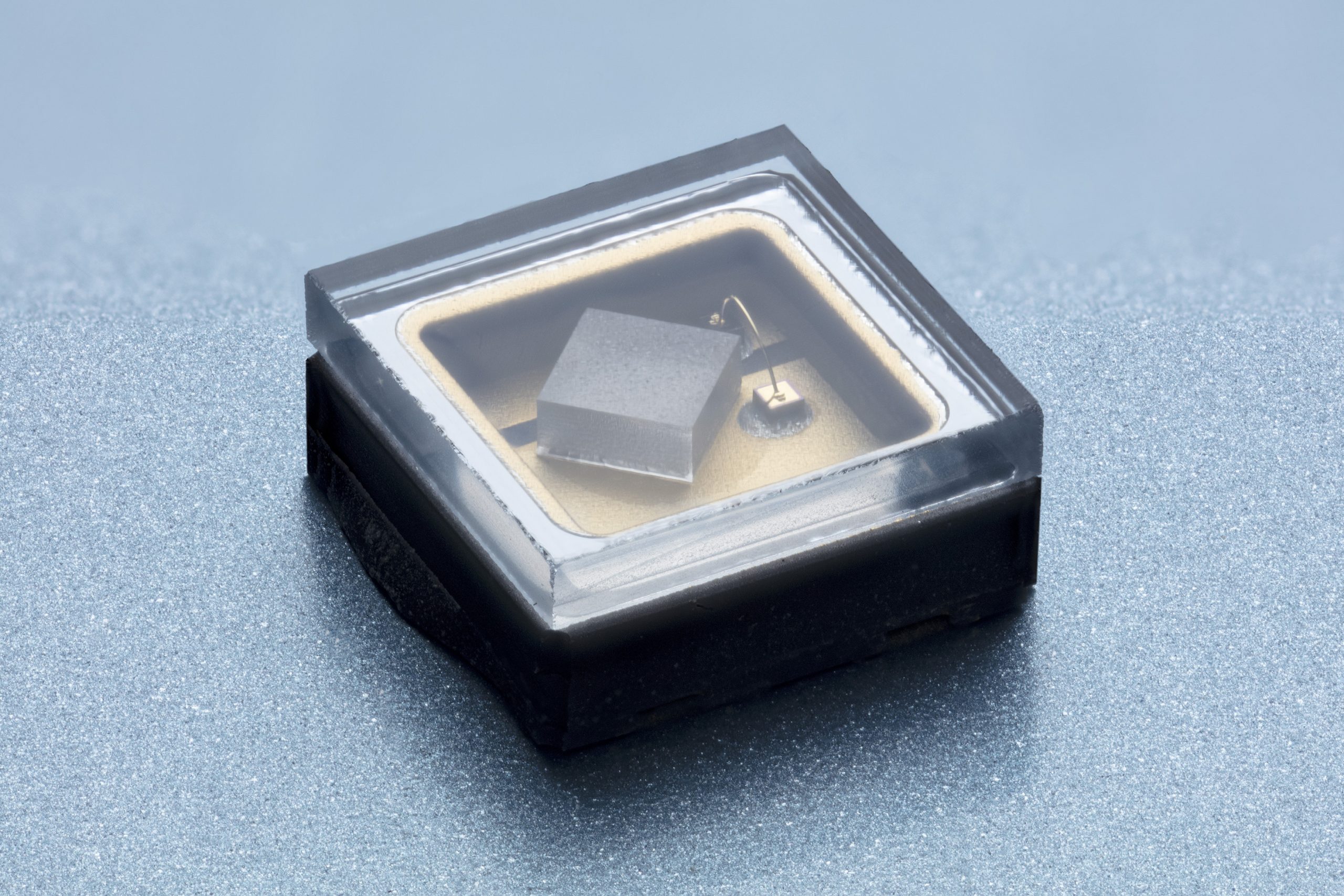
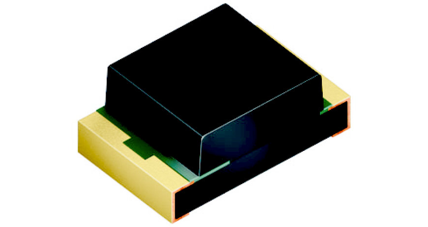
Osram Opto Semiconductors presents the SFH 5701 A01, a new ambient light sensor (ALS) with integrated circuitry (IC).
The SFH 5701 A01 ambient light sensor is Osram Opto Semiconductors’ latest addition to its portfolio for the automotive sector and the company’s first IC-based component for which a separate power supply pin is not required. The ambient light sensor (ALS) is an active component in which the IC is powered by the signal current and is therefore not reliant on an external power supply. It therefore has only two pins instead of three or more, making it much easier to connect and operate. The special filter encapsulation of the SFH 5701 A01 lets mainly green light through and filters out infrared wavelengths very efficiently. This ensures that the surface-mountable component is ideally adapted to the spectral sensitivity of the human eye, which also is most sensitive to light in the green range of the color spectrum. Overall, the sensor detects light in the spectrum between 450 nm and 700 nm – the visible range for the human eye.
SFH 5701 A01 is an analog component with a linear integrated amplifier which supplies a typical signal of 135 µA at 100 lux. The high dynamic range and high sensitivity at low illuminance of 0.01 lux combine to produce reliable light measurements for a wide range of ambient light conditions. The ALS delivers precise measurements even behind dark glass or plastic covers – a major benefit for passenger cell designs. Its footprint of 1.25 mm x 2.0 mm x 0.8 mm also means it is extremely compact. Integrated thermal compensation makes the component insensitive to fluctuations in temperature.
The dark green encapsulation of the package of our SFH 5701 A01 offers many benefits, not least in terms of design. The component is unobtrusive in the car, particularly if installed behind a semi-transparent cover. Together with its small size and high sensitivity, this makes the component a particularly versatile and efficient solution for many different in-car applications
,said Walter Rothmund, Marketing Manager Automotive for the Emitter Laser Sensor section at Osram Opto Semiconductors.
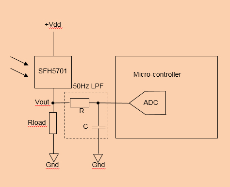
Block Diagram
The analog ALS IC has an analog current output proportional to the incident light level.
Rload converts the current output to a voltage output (VOUT): to interface to an ADC
This voltage output is typically applied to either the input of an ADC interface on an MCU or directly as an input to an LED driver IC equipped with auto-luminous control
RC low-pass filter to remove low-frequency flickering noise with a cut-off frequency (fc) of 50 Hz where fc = 1/(2*π*R*C)
Features
Simple implementation with just two pins
Built-in dark current compensation
Built-in thermal compensation
Close to human eye response
Excellent IR
Linear output
Small size: 2.0 mm x 1.25 mm x 0.8 mm
Wide dynamic range: 0.05 lx to 10,000 lx
Si photodiodes
SFH 5701 temperature range: -40°C to +100°C
SFH 5701 A01 (automotive version) temperature range: up to +125°C