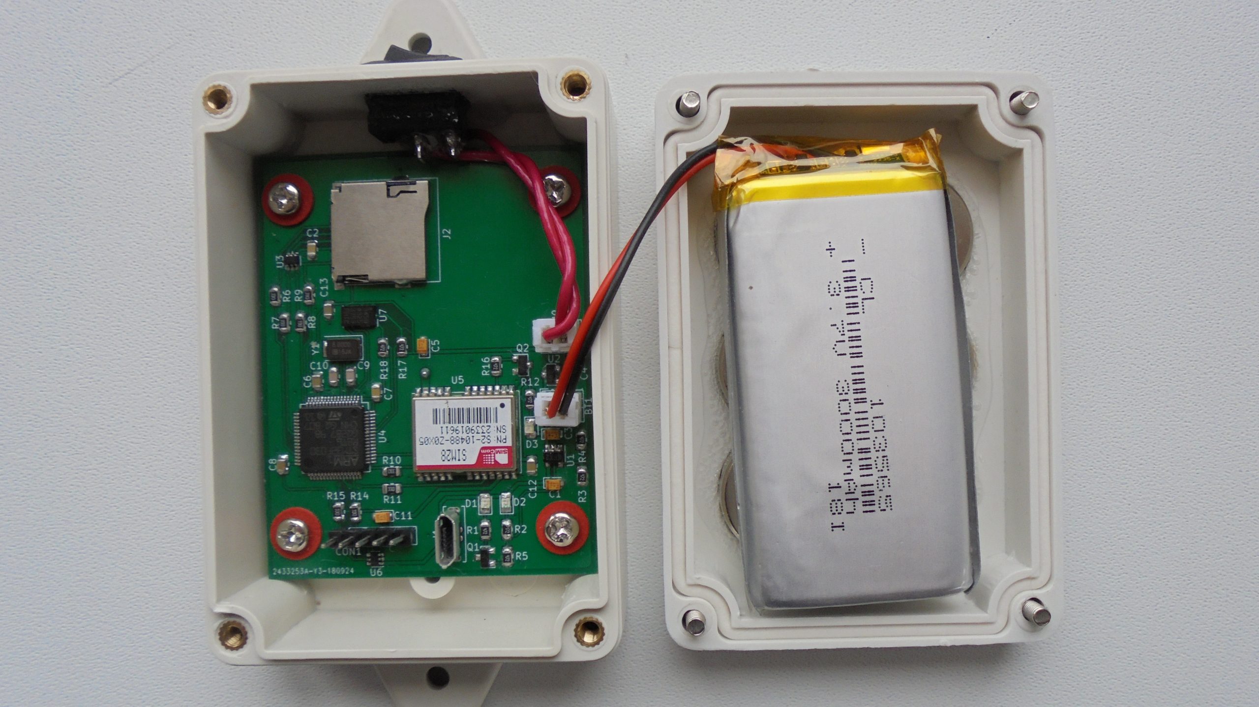
krakrukra has published his SD Card gps logger. He writes:
This device is an open source (both firmware and board level design) GPS data logger. You mount it with magnets on some vehicle, flip the power switch and the location data is saved onto SD card installed in the device. To increase battery life, device enters sleep mode when it sees no movement for 60 seconds and when some activity is detected it starts to save new incoming data in a new file. Files are named TRK*.TXT, where * is a number of the track. Files are named in the order they are created. After enough data was saved, you retrieve the device and convert the NMEA dump files in a gpx format file (with a program such as gpsbabel) and then you feed the gpx file to some analysis software (example: viking). All these example softwares are open source and available for many OS types.
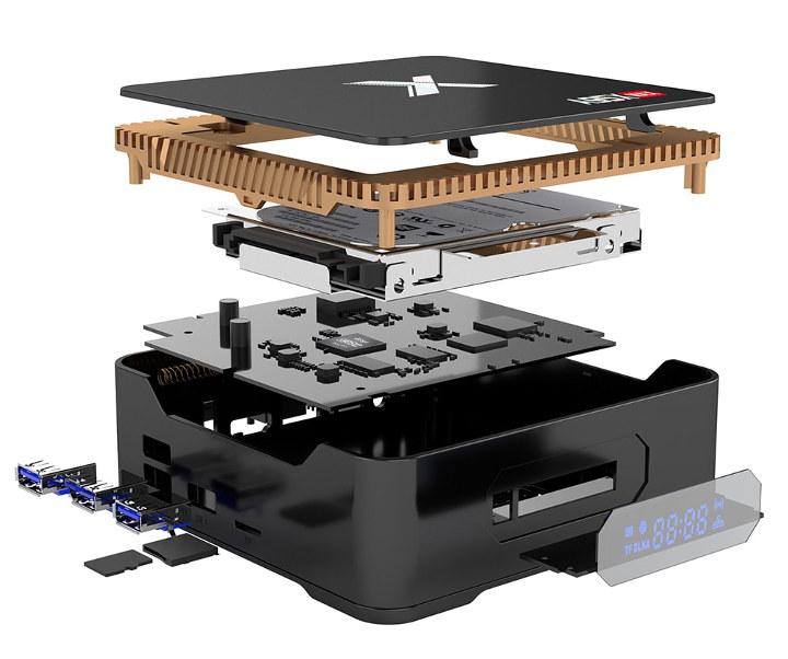
Different models of the Amlogic TV boxes have been released so far, one of those was the X96 Max or the Beelink GT1 Mini which doesn’t provide support for internal storage. The newest version of these TV boxes is the A95X Max which has been updated based on the previous version, contains all the features of its predecessor (The X95 MAX).
This new box is one of the first TV Boxes to run on Android Oreo (Android 8.1) but the major talking point of this box is the support of internal SATA storage options either SSD or HDD as compared to the process of attaching the storage externally through one of the USB 3.0 or USB 2.0 ports of the other devices. This gives the A95X Max a cleaner and a less bulky look.
Just like the X96 Box, it also comes with similar features. It provides support for multiple video codecs, HDMI with CEC support and the presence of a dual-band Wi-Fi that ensures higher transmission of data.
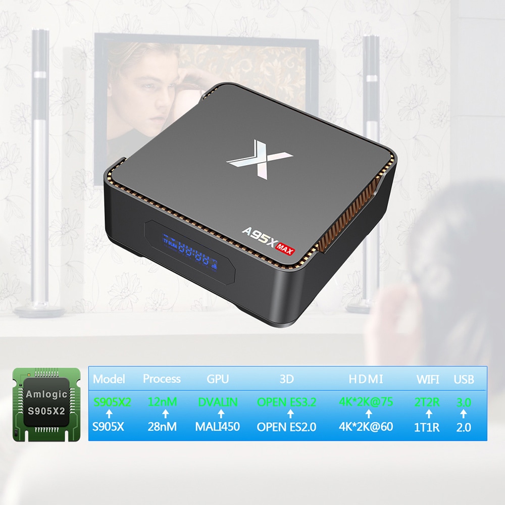
The below are some of the features of A95X Max
SOC: It has the Amlogic S95X2 quad-core Arm Cortex-A53
RAM: It comes with a 4GB DDR4
Wi-Fi: The A95X Max comes with a 2.4Ghz and 5Ghz band, which ensures faster data transmission.
Memory: It comes with 64GB eMMC for better performance and ease when downloading applications.
Storage: There is a micro SD card slot up to 128GB. 64GB eMMC flash, micro SD card slot up to 128GB, support for internal SATA SSD/HDD
It supports a 4k High Dynamic Range (HDR) image content. One can watch videos or play games and experience the feeling, because of the scenes and images which are shown like reality.
USB Interface: USB 2.0 and USB 3.0 ports.
Video Codecs: These help with compressing and decompressing digital videos. Some of the video codes included are: the VP9 Profile-2, the 10-bit H.265, AVS2-P2, and MPEG-4 ASP.
Dimensions: 13cm by 13cm by 4.5cm.
Weight: 260 grams.
Power Type: External Power Adapter Mode and Digital Power Supply.
Bluetooth: Bluetoot4.2.
Android: Android Oreo (Android 8.1)
Aside from supporting SATA on the A95X Max TV Box, there isn’t much difference with the previous version box. Even the SATA support is still limited, the design is not a full fledge SATA but rely on a USB 3.0 to SATA bridge. That means there’s no performance improvement to expect.
The entire package comes with the TV box, a remote control, a power cable, an HDMI cable, and a user manual. The package weighs 0.425 kg and is being sold on Gearbest. It also being sold on geek buying, which is giving it about a 38% discount.
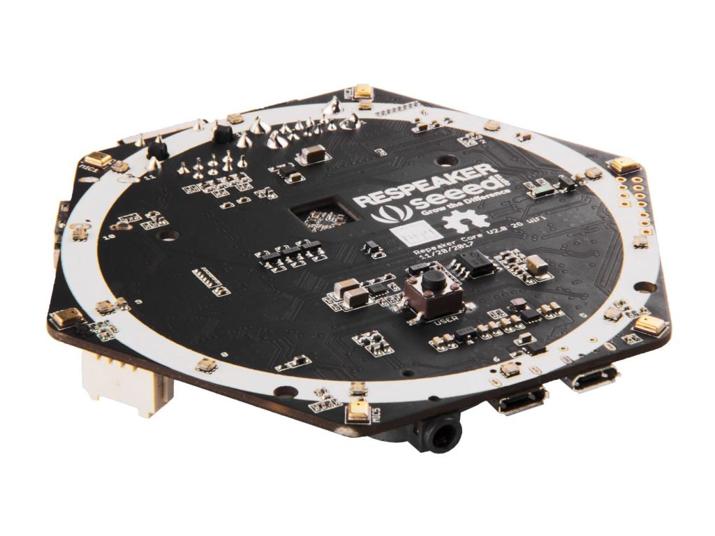
The ReSpeaker Core v2.0 allows developers create powerful and impactful voice and sound interfaces. Suitable to use as a base for smart assistance as well as responding to environmental sounds, the ReSpeaker Core v2.0 was designed with the idea that developers deserve to have many options available to them.
We received much feedback from ReSpeaker Core v1 users and have added many requested features. Different from the original board this SBC is running Debian* with an onboard microphone array and software based voice enhancement algorithms.
A High Performance Platform
The ReSpeaker Core v2.0 is powered by the Axol Core module, featuring the Rockchip RK3229 Quad-Core Cortex-A7 with a Mali 400MP GPU, 1GB of DDR3 RAM, and a PMU. The core runs the Debian OS. This provides developers with much more flexibility and resources to create their projects.
Around the core are peripherals including a Kingston 4GB eMMC to enable the OS to run onboard, a WiFi/BLE module, USB, Grove, and HDMI connectors, the on board 6-mic array, LED ring, and more.
New in our ReSpeaker product line is a software based approach to voice enhancement. The more powerful Axol Core allows the Core v2.0 to process the audio received through the 6 far field microphones in real-time. The ReSpeaker Core v2.0 supports Noise Suppression (NS), Keyword Wakeup, Direction of Arrival (DoA), Beam-forming (BF), Acoustic Echo Cancellation (AEC). Our BF and AEC algorithms are provided by Alango, a professional audio DSP company used in the automotive industry.
An Open Software Ecosystem
We recognize that each project has different requirements and goals. As such we have worked to provide as much flexibility to developers as possible. Our quad-core solution allows us to run numerous software solutions. From the selection of algorithms, NLP services, smart assistants, operating systems, and more, we wish to support our users. If you have suggestions on what services you would like to see us officially support let us know on our forums, or if you enjoy the work yourself, submit a merge request to our github.
Features
Debian-Based Linux System
SDK for Speech Algorithms with Full Documents
C++ SDK and Python Wrapper
Speech Algorithms and Features
Keyword Spotting (Wake-Up)
BF (Beamforming)
DoA (Direction of Arrival)
NS (Noise Suppression)
AEC (Acoustic Echo Cancellation) and AGC (Automatic Gain Control)
All-in-One Solution with High Performance SoC
8 Channel ADC for 6 Microphone Array and 2 Loopbacks (Hardware Loopback)
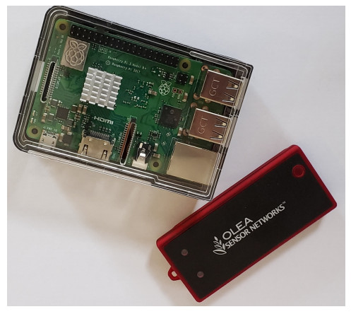
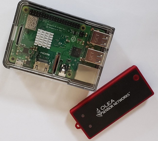
Olea Sensor Networks made their “OS-3010” healthcare sensor module compatible with Raspberry Pi. It supports Windows, Linux, and other Android devices. The sensor module monitors heart rate, respiration, and other signals incorporated by OleaSense software. At 84 x 35 x 8.7mm, the 29-gram OS-3010 is entirely enclosed and built to fit into a pocket or badge-holder of medical personnel or patient. It can also be attached to a patient’s bed for round the clock monitoring. The company says It can reduce the need for healthcare professionals to continually take and record patient data while avoiding user input errors. It also enables easy, long-term in-home monitoring. Restrictive methods for patients monitoring can be substituted, like the Holter Monitors or Spirometers.
The OS-3010 can improve health care in rural areas, and developing nations. Bluetooth 4.2 radio and micro-USB port is available for host systems communication. The sensor operates on a Cortex-M4 MCU and incorporates a 16-bit data acquisition (DAQ) interface as well as an Olea Vital-Sign Sensor — a 24GHz (K-Band) CW Doppler radar sensor, magnetometer, accelerometer, gyroscope, and LED are available. Power consumption is 200mW (40mA at 5V) and comes with an 8-hour 150mAh Li-ion battery. A wall adapter and an optional in-vehicle adapter are available. The device supports -40 to 85ºC temperatures.
The Sensor can work without contact with the patient’s body, and it uses ML algorithms to analyze, aggregate sensor data, and present actionable data about a patient’s condition in real-time. An authentication engine that can identify an individual’s unique heartbeat, which is called a HeartSignature is included in the sensor. The dashboard visualization GUI is called the QSN Quadcorder. The software is available for Linux, Android, and Windows, and it creates a summary and plots data processed by Olea sensors.
The researchers are working on the application of the OleaSense in providing statistical data for analysis of conditions like mild cognitive impairment (MCI) of patients with chronic kidney disease (CKD). The device complies with ETSI 300 440 and FCC 15.24 standards but is not certified yet for clinical use. There is no disclosed price for the OS-3010, but it is available now.
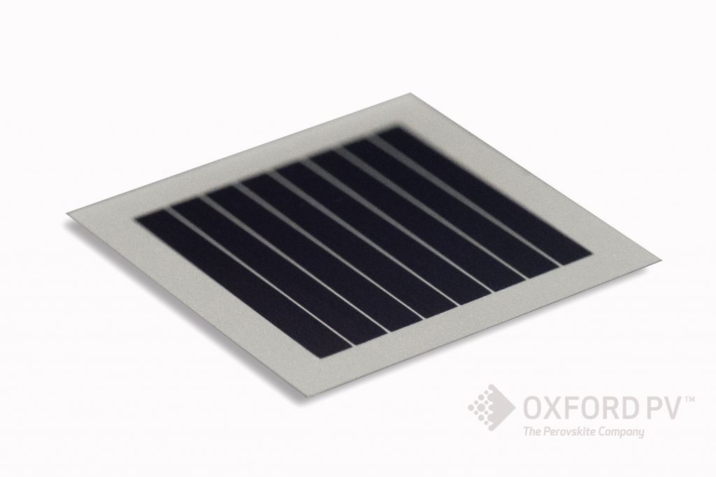
Perovskite solar technology leader’s solar cell sets new world record.
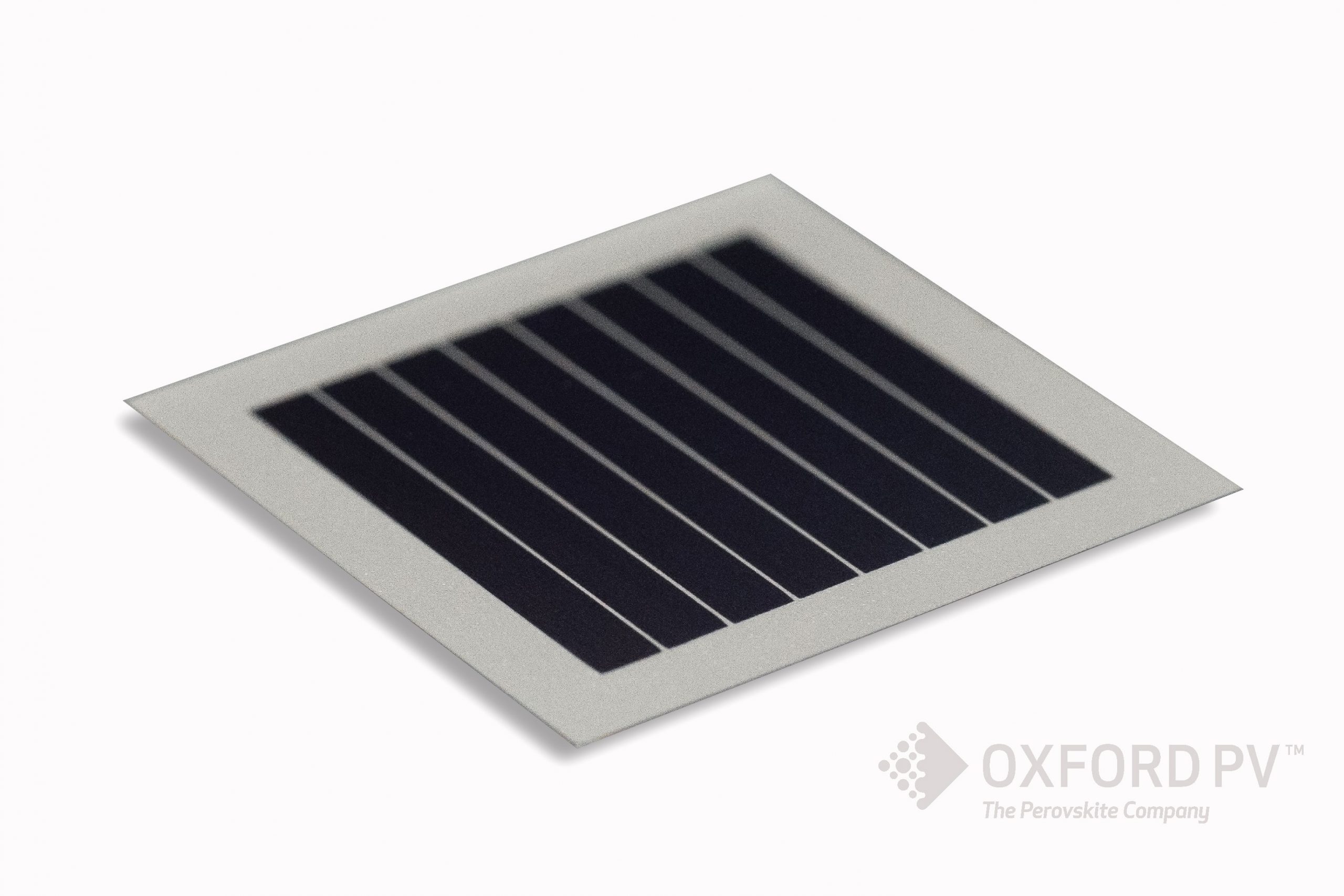
Oxford PVTM – The Perovskite CompanyTM, the leader in the field of perovskite solar cells, today announced a new, certified, world record for its perovskite based solar cell.
Oxford PV’s 1 cm2 perovskite-silicon tandem solar cell has achieved a 28% conversion efficiency, certified by the National Renewable Energy Laboratory. The achievement edges out Oxford PV’s own previous certified record of 27.3% efficiency for its perovskite-silicon solar cell, announced earlier this year.
Dr Chris Case, Chief Technology Officer at Oxford PV commented,
Today’s record demonstrates the unprecedented pace of our technology development. We are continuing to push our perovskite-silicon solar cell technology, with a roadmap that extends beyond 30% efficiency. The solar cells we are developing are not only efficient but also stable. Similar devices from our research and development facility have passed at least 2000 hours of damp heat reliability testing, in line with IEC 61215 protocol.
Frank P. Averdung, Chief Executive Officer at Oxford PV added,
2018 has been a significant year for Oxford PV. Alongside the pace of our technology advancements in both efficiency and stability, our pilot line is routinely producing commercial sized tandem solar cells for validation by our development partner – a major manufacturer of silicon solar cells and modules. With new collaborations with key industry players strengthening our manufacturing capabilities, the foundations are in place, to move perovskite photovoltaics into commercial phase.
Display technology is constantly approving, from the days of the 16×2 LCD to today of the various cool displays like the E-paper and OLED displays, efforts keep going to make them even better, with more colors and lower power consumption among other features. This makes them the perfect component for user interface in electronic projects. Monochrome OLED displays are a product of such advancement and we have used them in a couple of projects on this website but despite the fact that they are low power, quite bright and easy to use, they are monochromatic, which means they have one or a few colors available. So I was quite excited when I came across a colored OLED display and felt it will be a great idea to make ta tutorial on how to use this display in Arduino projects.
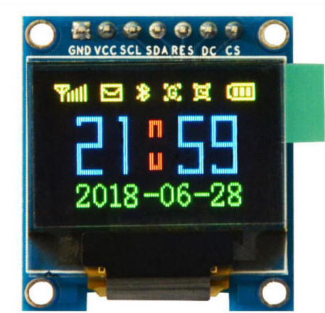
0.95″ Color OLED Display
For today’s tutorial, we will use the 0.95″, SSD1331 based colored OLED display. This display, just like all other OLED displays, is low power (consumes just 25mA when all the pixels are on) and offers brightness levels greater than what is available with LCDs. It has a resolution of 96×64 pixels and can display over 65000 different colors. It communicates over SPI, which means, asides from VCC and GND, it will use 5 of the Arduino GPIO pins.
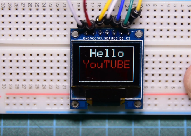
To demonstrate how to use this display in your projects, we will create a simple sketch which will show a YouTube subscribe button on it. The code will be properly explained, so it is easy for you to modify and adapt it to the needs of your projects.
Required Components
The following components are required for this project;
As usual, the exact components used for this tutorial can be purchased via the links attached to them.
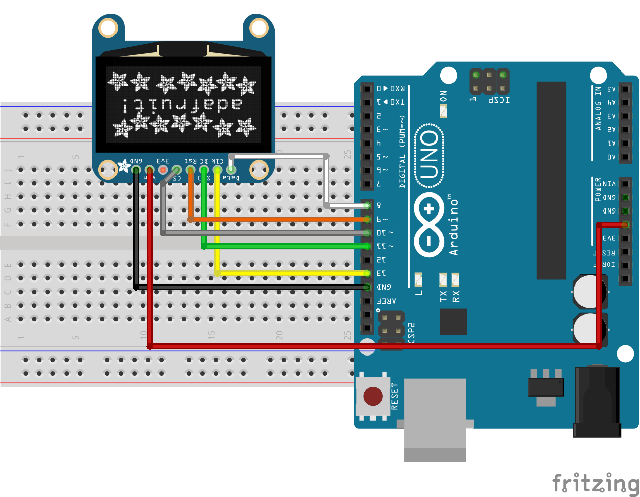
Schematics
The schematic for this tutorial is quite easy as it involves just the OLED display and the Arduino. Connect the OLED display to the Arduino as shown in the schematics below.
Schematics
To make room for variations in pin labels and make the schematics easier to follow, the connections between the Arduino and the OLED display is further described below.
Ensure the connections are as described above. You can check the datasheet of your display in case the pin labels does not match the one above.
Code
The code for this tutorial is heavily depended on the Adafruit SSD1331 OLED driver library for Arduino. The library was created specifically for use with displays that are based on the SSD1331 display driver. I created a demo sketch for this tutorial and will go over the functions and statements in detail so you can learn how to adapt it for use in your own projects. In addition to the SSD1221 OLED library, we will also use the Adafruit GFX Library along with the Arduino SPI library.
As usual, we start by including the libraries that will use on our sketch. After this, we declare the pins of the Arduino to which the pins of the OLED are connected and also declare variables to hold some of the colors that we will use.
#include <Adafruit_GFX.h>
#include <Adafruit_SSD1331.h>
#include <SPI.h>

#define sclk 13
#define mosi 11
#define cs   10
#define rst  9
#define dc   8

// Color definitions
#define  BLACK           0x0000
#define BLUE            0x001F
#define RED             0xF800
#define GREEN           0x07E0
#define CYAN            0x07FF
#define MAGENTA         0xF81F
#define YELLOW          0xFFE0
#define WHITE           0xFFFF
Next, we create an object of the Adafruit SSD1331 library with the DC, CS and RST pins as arguments.
Next is the void setup() function. We use the display.begin() function to start communications with the display. With this done, we use the display.fillScreen() function to create and switch between multiple backgrounds for the display. To display text, we use the display.print() function with display.setTextColor() and display.setTextSize() to respectively set its color and font size. All of these functions were used to create a Youtube subscribe button.
Up next is the void loop() function. The code under the loop function is similar to that of the setup() function. We created two boxes, one with a black background and the other with a red background using the display.fillRect() function. Then we wrote the text “subscribe” on it using the display.setCursor() function to position the text.
There are several other functions in the SSD1331 Arduino library that you may find useful for your projects. You can check all the functions and their usage in the library documentation here.
Demo
Copy the code and upload to your Arduino Uno. Ensure everything is connected as described under the schematics section. If you follow the steps correctly, you should see your screen come up as shown below.
Demo
That’s it for this tutorial guys. What cool projects do you think will be a perfect fit for this display? Ensure you drop a comment.
As usual, the video version of this tutorial is available on youtube.
The STPW12 is an integrated electronic power breaker, optimized to monitor the input power. Connected in series to the power rail, it is able to disconnect the electronic circuitry on its output if the power consumption overcomes the programmed limit. When this happens, the device automatically opens the integrated power switch and disconnects the load.
The intervention of the protection is communicated to the board monitoring circuits through a signal on the fault pin.
After a certain delay time, programmable by the user, the device automatically tries again to close the internal switch and re-connect the load.
A dedicated monitor pin provides the user with continuous information on the monitored power.
The device can be enabled/disabled through a dedicated pin, and a direct PWM mode can be implemented providing PWM pin with an external signal.
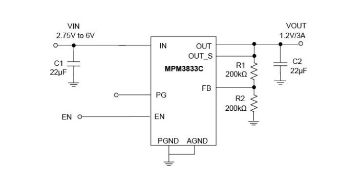
The MPM3833C from Monolithic Power Systems, Inc is a step-down module converter with built-in power MOSFETs and inductor. The MPM3833C achieves 3A of continuous output current from a 2.75V to 6V input voltage with excellent load and line regulation.
The MPM3833C works in forced continuous conduction mode (CCM) and has a voltage ripple under 10mV with one output capacitor, making it suitable for optical modules, FGPA, ASIC, and other applications requiring low ripple noise.
The output voltage can be regulated as low as 0.6V. Only FB resistors, input capacitors, and output capacitors are needed to complete the design. Also available is the EVM3833C-RH-00A evaluation board.
The constant-on-time control (COT) scheme provides fast transient response, high efficiency, and easy loop stabilization.
Full protection features include cycle-by-cycle current limiting and thermal shutdown.
The MPM3833C requires a minimal number of readily available, standard, external components and is available in an ultra-small QFN-18 (2.5mmx3.5mmx1.6mm) package.
Summary of features:
2.75V to 6V Operating Input Range
Adjustable Output from 0.6V
Low Radiated Emissions (EMI) Complies with EN55022 Class B Standard
Up to 3A Continuous Output Current
100% Duty Cycle in Dropout
Forced Continuous Conduction Mode (CCM)
Enable (EN) and Power Good (PG) for Power Sequencing
Cycle-by-Cycle Over-Current Protection (OCP)
Short-Circuit Protection (SCP) with Hiccup Mode
Only Four External Components Needed
Available in a QFN-18 (2.5mmx3.5mmx 1.6mm) Package
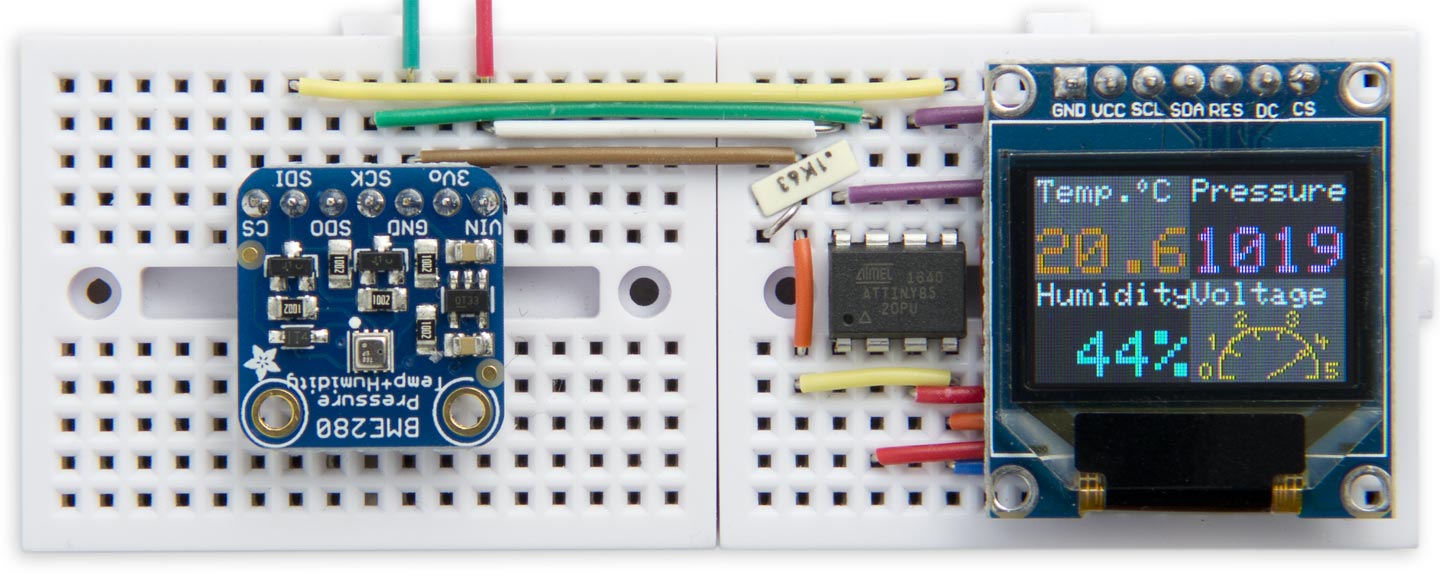
This is a weather station based on an ATtiny85 and an Adafruit Bosch BME280 sensor breakout. It displays the atmospheric temperature, pressure, and humidity on a 96×64 SD1331 colour OLED display. by David Johnson-Davies:
To display the readings the Weather Station uses a low-cost 96×64 OLED display with 64K colours, and an SPI interface. It’s available from a number of suppliers including Adafruit [1] or Banggood [2].
The Weather Station is based on a Bosch BME280; it’s is the perfect sensor for a home weather station as it provides temperature, pressure, and humidity in a single device [3]. It’s available on a breakout board from Adafruit [4], Sparkfun [5], or Chinese suppliers such as AliExpress and Banggood. Some boards, such as Adafruit’s, support either 5V or 3.3V operation, so check before buying if this is important to you.
The downside with this sensor is that you have to do quite a bit of calculation to get the final readings; it’s not just a case of reading the values from the device via I2C or SPI, as with some other sensors. Both Adafruit and Sparkfun provide a library to interface to the sensor, but unfortunately these don’t seem to work on ATtiny processors, such as the ATtiny85, so I set about writing my own Tiny BME280 library.
ATtiny85 Weather Station with SD1331 OLED display – [Link]
IoT, known as the Internet of Things is usually referred to as the billions of physical devices around the world that are connected to the internet, sensing, collecting and sharing data with some of them even going the extent of doing some actuation. Today’s IoT is a super big industry (if there is anything like that) worth over a billion-dollar market and is still growing all thanks to the availability of open-source technology and good enabling platform.
IoT Market Value Estimation
IoT has found applications in several domains even to the least expected. Its applications have been used in the Agriculture space, Energy, Health, Homes, Industrial Environment, Security, Retail, and many more. With advanced technology like LoRaWAN and even traditional technology like 2G has made IoT applications to be deployed to the most obsoletes places you can imagine.
Recently I got asked about “What are the Programming Languages Used In the IoT Working Market,” it was an unexpected question because I haven’t taught about it in depth. It was like, these devices connecting to the internet every day making our lives better and making us more aware of our environment, how do they talk to each other? What language do they speak to the internet or to each other? So what are the top programming language for the developers and engineers building IoT solutions?
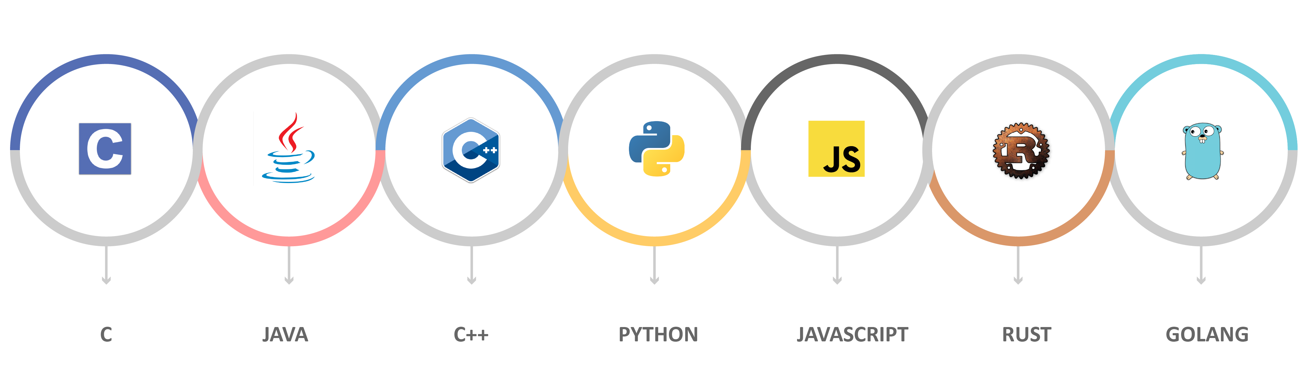
Programming Languages used for IoT development
C –
I don’t think we have a right to talk about the Internet of Things without talking about C unless you are not concerned about edge computing level. C is the number one to me, and it is what powers most embedded system (at least most microcontroller system). The language is ideal for writing low-level code, giving users the full power of using the memory and the processor usage as it wishes thus squeezing out all possible performance. C remains the language of choice for constrained devices.
Java –
Java’s portability and robustness give it unlimited capabilities in building the Internet of Things applications. Java already used in several domains can easily get deployed to embedded platforms by using the Java Virtual Machine capability, and the same code can be used in another place.
Java is an OOP (Object-oriented programming) language which will be very handy in some applications where languages like C will struggle. Java is used in gateway nodes or aggregator nodes and devices that run operating systems like Linux.
Python –
The love showed to Python is one that won’t be stopped any time soon. Once started as a high-level scripting language but is now being used as the primary language for many users. Embedded devices with enough memory and computational power can easily be programmed with Python, and a lot of developers are taking their chances with it.
Moreover, Python is easy to learn, and the code is relatively easy to understand. Python is the language of choice for one of the most popular microcontrollers on the market, the Raspberry Pi. Just like Java, Python is a cross–platform language and will run on any devices that have the Python interpreter installed. I think the future will favor Python because of the push of organization of complex data streams, machine learning, and deep learning-related applications.
PHP & Javascript –
PHP is one of the most used server-side languages and can easily find application in the IoT domain especially when working with a custom database or special server requirements. It can be used as a middleman when trying to lift out some of the computations from the edge devices.
Javascript is in a world of its own especially when you work with the right stack. Not only because of it’s easy to deploy it on the web, but it is also being adapted to run on embedded devices like the Espruino and Tessel hardware platforms giving web developers the privilege of moving to the edge level without learning a different language.
So those are some of the most powerful and sort after languages used in the IoT Market, let me know what languages deserve to be added on the list or which ones do you think deserved to be mentioned here?