Nvidia Unveils The New AI Brain For Machines and a Cheaper Jetson TX2

Nvidia, is one of those companies that never ceases to amaze me. I have to say that they have technically monopolized the GPU ecosystem and now Nvidia is gaining (if not already) for a new crown – AI on the Edge.

AI in the cloud has been the buzz ever since, enabling numerous application to be able to achieve Artifical intelligence capabilities without much effort. Of course, this is a good idea, and multiple players are gaining for this. I believe cloud computing is great – but it alone isn’t enough. So many things come into place here, centralization, privacy (who really controls the data), security, and most crucial physics (there is a limit of the data we can receive and push). But AI on the Edge brings a different dimension to this, you indeed have control of so many things and most importantly build to your imagination.

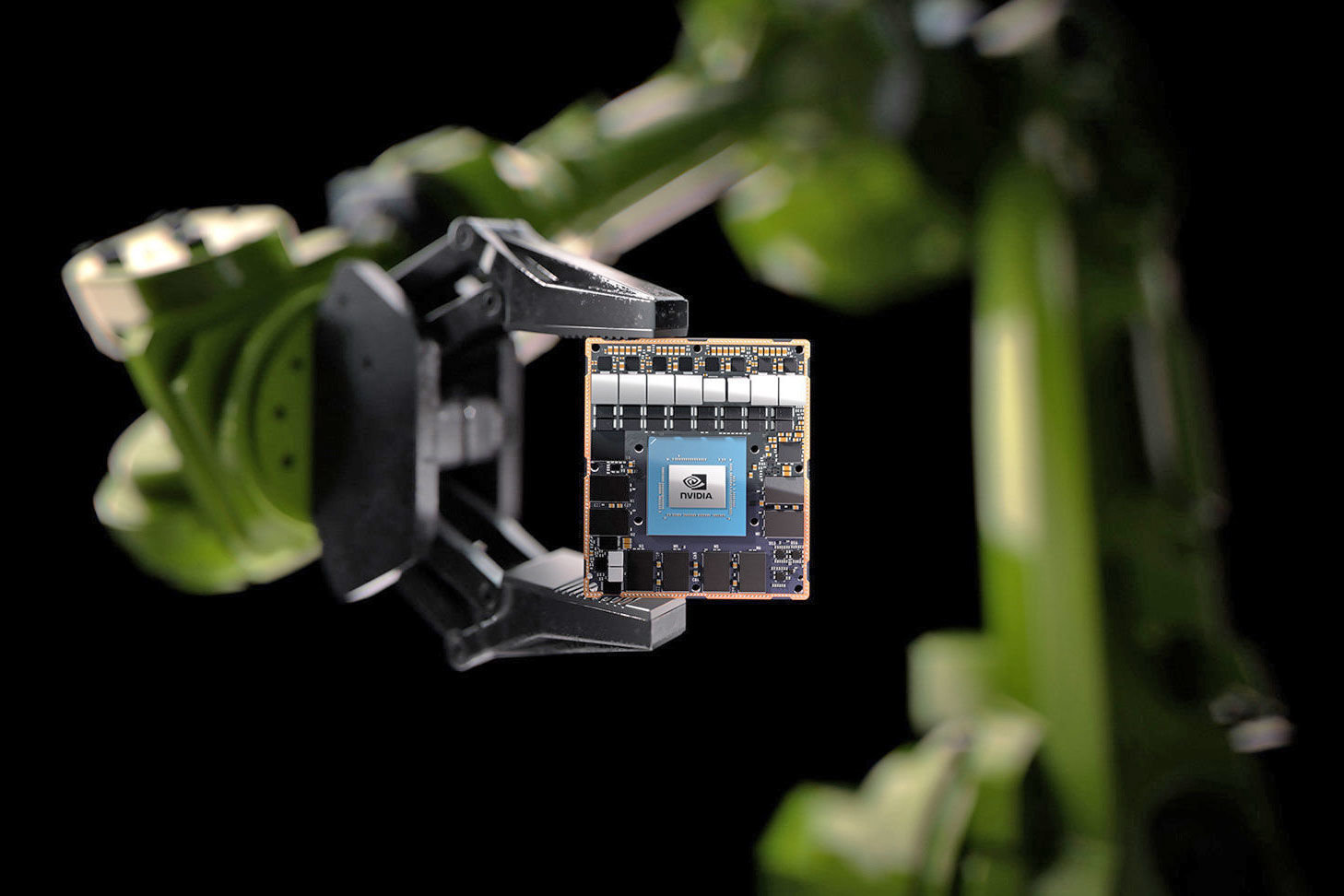
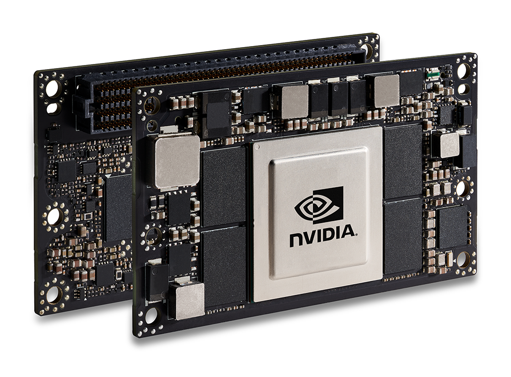
With AI on the Cloud, we put critical assets and infrastructure at risk of attack and might not even get the performance we geared for especially in the case of autonomous machines. However, Nvidia has been pushing for edge infrastructure to enable AI on the Edge with its numerous arrays of AI enabled hardware, but the unveiling of the Jetson AGX Xavier Module will be a total game changer. It promises to give robots and other intelligent machines the processing juice they will ever need for their AI brains.

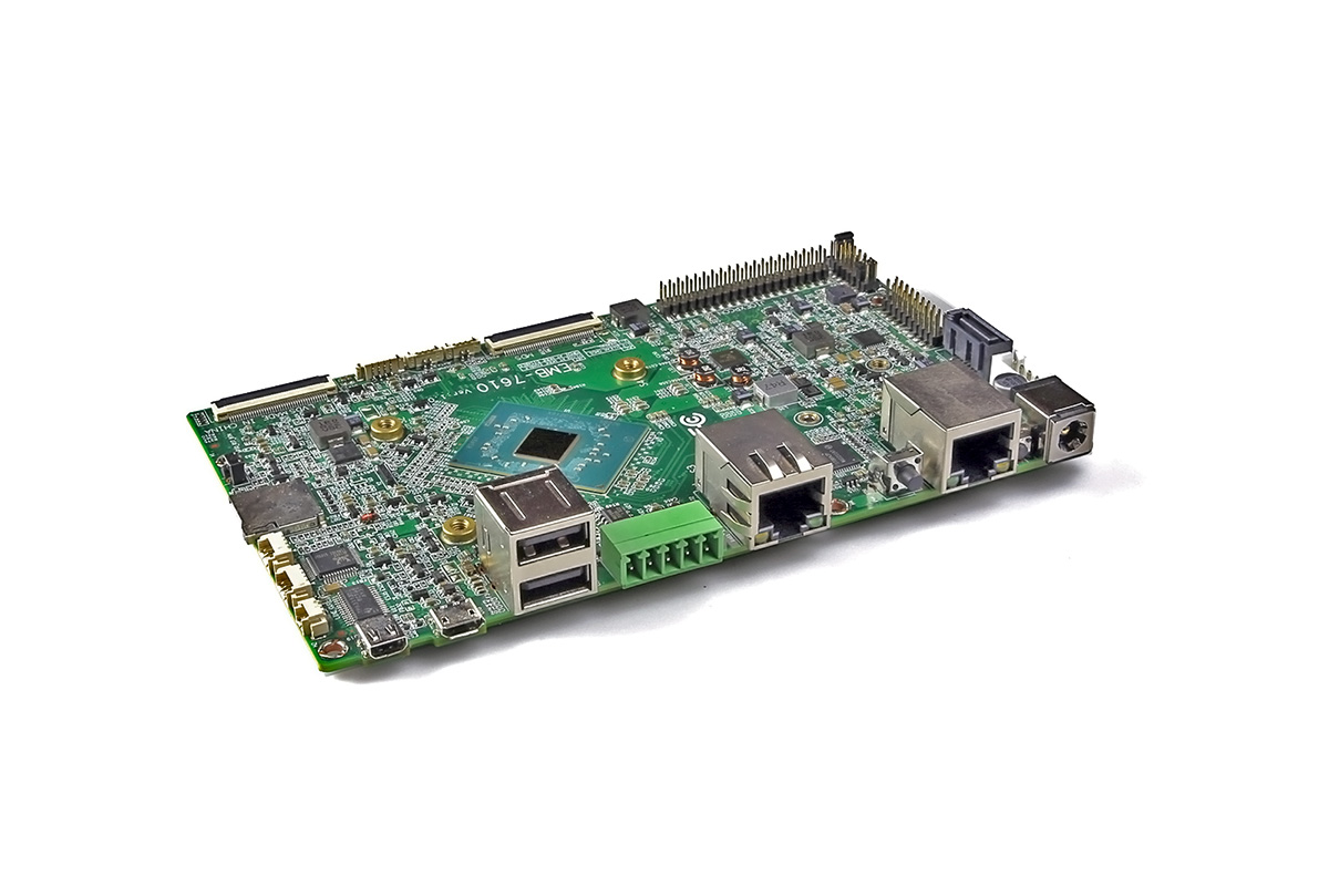
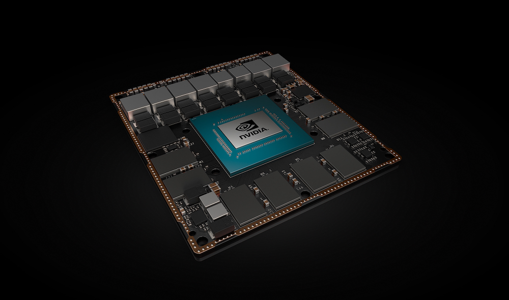
Nvidia announced the Xavier platform earlier this year and has now added the AGX to the Jetson Xavier name. The AGX Xavier module is built around the Xavier system-on-chip which relies on six processors to get its work done, including a 512-core Nvidia Volta Tensor Core GPU, an eight-core Carmel Arm64 CPU, two NVDLA deep-learning chips, and dedicated image, vision, and video processors. Here comes the impressive part of it; the AGX Xavier module delivers up to 32 TOPS (30 trillion computing operations per second) of accelerated computing capability while consuming under 30 Watts. That’s more than 20X the performance and 10X the energy efficiency of the Jetson TX2. Users can configure operating modes at 10W, 15W, and 30W as needed.

Nvidia Jetson AGX Xavier

The module is available with a BSP with Nvidia’s Linux4Tegra stack, and as previously announced, Nvidia also offers an AI-focused Isaac SDK. The AGX Module is not designed for the everyday user though, and it costs $1,099 each in batches of 1,000 units. The AGX Xavier Module can handle visual odometry, sensor fusion, localization and mapping, obstacle detection, and path planning algorithms making it ideal for high demanding robots and other autonomous machines that need a lot of performance with relative low power use.

Nvidia Jetson TX2 4GB

Joining the Jetson Family is the newly introduced Jetson Tx2 4GB which is expected to be cheaper than the 8GB Jetson TX2. Like the earlier TX2 modules, the 4GB version features 2x high-end “Denver 2” cores and 4x Cortex-A57 cores. You also get the 256-core Pascal GPU with CUDA libraries for running AI and machine learning algorithms. Basically the same Jetson TX2, with low memory specs.

The Nvidia’s Jetson TX2 4GB is expected to be available in June 2019 and pricing is rumored to be around $299 for 1000 volumes. The Jetson AGX Xavier is available now starting at $1,099 per module for 1,000-plus purchases. More information may be found in Nvidia’s announcement, and it’s Jetson TX2 4GB product page.
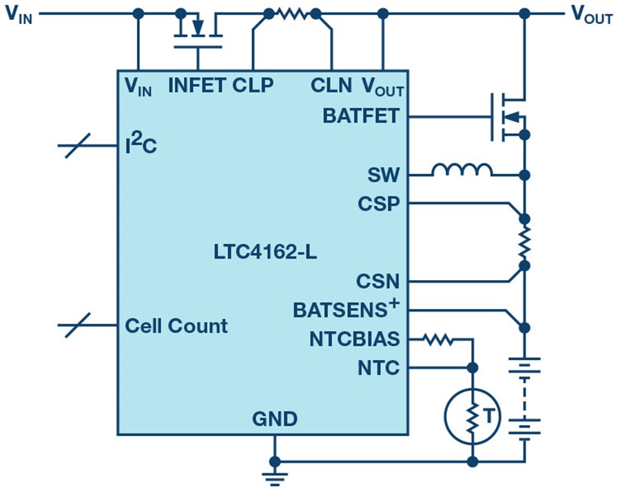
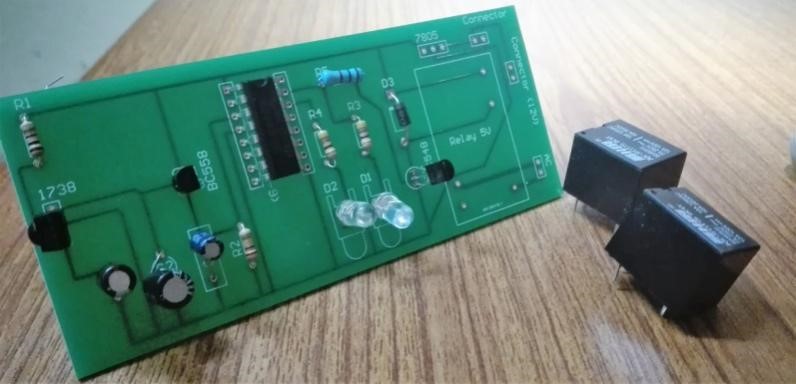
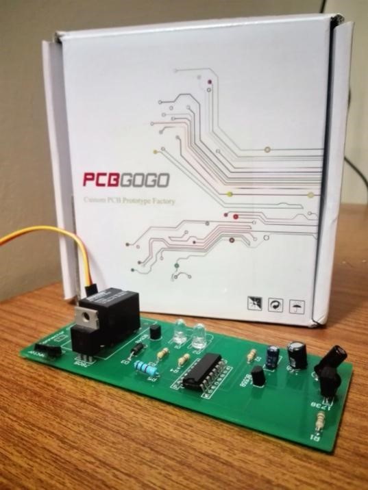
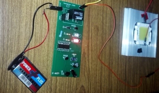
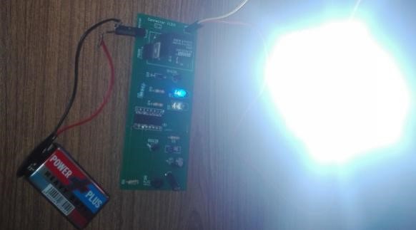
VCSELs integrate micro lens array for 3D sensing

Osram Opto Semiconductors has unveiled the PLPVCQ 850 and the PLPVCQ 940, the latest additions to its Bidos product family. Applications for the new Vertical Cavity Surface Emitting Lasers (VCSELs) include machine vision or facial recognition, as well as object or architectural scanning that involves mapping an area in 3D and positioning virtual furniture and other items. The application helps save time and money when designing spaces.  

VCSELs combine the high power density and simple packaging of an IRED with the spectral width and speed of a laser. Unlike laser diodes, VCSELs and are much less sensitive to temperature fluctuations. One of the most familiar applications for the technology is facial recognition for mobile devices. VCSELs illuminate the face with infrared light for cameras. The image captured by the camera is then compared to the image stored on the device. If they match, the device is unlocked. These 3D sensing applications now possible use PLPVCQ 850 and PLPVCQ 940 for Time of Flight (ToF) measurements.

The new VCSELs come with a compact black package measuring only 2.40 mm x 3.30 mm x 1.20 mm. Depending on the application, the customer can select the 2 W component with the appropriate wavelength – either 850 nm (PLPVCQ 850) or 940 nm (PLPVCQ 940). The infrared beam is formed with the aid of a special micro lens array to achieve exceptionally homogeneous illumination of the field of view (FOV). Another benefit of the VCSEL chip from the Osram subsidiary Vixar is the ease of installation.

We are delighted to add these highly innovative products to our VCSEL family. With these products we are setting new standards in emerging applications such as 3D sensing, and with our know-how we are looking to gain significant influence in this market

said Nina Reiser, Marketing Manager at Osram Opto Semiconductors.

The two new products will be available in the first half of 2019. For more information on VCSELs at Osram Opto Semiconductors go to: https://www.osram.com/os/products/product-promotions/vcsel/bidos-family.jsp

Miniature Solar Cells Embedded in Clothes can Charge your Mobile

Clothing embedded with tiny solar cells the size of a flea can allow wearers to generate electricity on the move and charge items like mobile phones and smartwatches.

Miniature technology is a claim in today’s world. We talked recently about the tiny gyroscope which is the size of a grain of rice, and now clothes embedded with miniature solar cells the size of a flea can allow wearers to generate electricity outdoors, and charge items like mobile phones and smartwatches. The cell developed by Nottingham Trent University. They discovered a way to embed miniaturized solar cells into yarn that can then be knitted or woven into textiles.

This technology has undergone testing and proven to charge a mobile phone and a Fitbit. The cells are encapsulated in a protective resin which enables the textile fabric to be washed and worn like any conventional cloth. The three millimeters in length and 1.5 millimeters in width cells are almost invisible to the naked eye and cannot be felt by the wearer. This makes the garments appear the same as any regular form of clothing despite having the capability to generate electricity.

The solar cells measure only 3mm in length and 1.5mm in width.

According to project lead Professor Tilak Dias, of the School of Art & Desig:

By embedding miniaturized solar cells into yarn we can create clothing and fabric that generate power in a sustainable way. The clothing would look and behave like any other textile, but within the fibers would be networks of miniturized cells which will create electricity. This could do away with the need to plug items into wall sockets and reduce the demand on the grid while cutting carbon emissions. The electrical power demand for smart e-textiles has always been its flaw and this technology will allow people to use smart textiles while on the move.

The university’s Advanced Textiles Research Group created a proof of concept textile of 5cm by 5cm size with 200 cells. The 200 miniaturized cells can generate 2.5-10 volts and up to 80 miliwatts in power, this generates enough power to charge a mobile phone and a Fitbit. According to researchers, if 2,000 solar cells were integrated into a textile it would generate enough power to charge a smart phone.

Researcher Achala Satharasinghe, who developed the prototype said:

the technology could revolutionize the way we think about solar power, clothing and wearable technology. Also, with the availability of miniaturised solar cells we will be able to generate power in a host of new ways, by utilising things like clothing, fashion accessories, textiles and more. It will enable mobile devices to be charged in environmentally-friendly ways which are more convenient for consumers than ever before.

We don’t know yet when the panels will be perfected for commercial use. We hope it is soon.

Visit Nottingham Trent University for more information.

LTC4162 Charges batteries from Solar Cells using MPPT

35V/3.2A Battery Step-Down Battery Charger with PowerPath and I2C Telemetry. by Zachary Pantely @ analog.com

The first step to designing a battery charger is choosing a battery charger IC from the vast field of available solutions. To make an informed decision, a design team must first clearly define the battery parameters (chemistry, cell count, etc.) and the input parameters (solar, USB, etc.). The team must then search for chargers that fit the input and output parameters, comparing numerous data sheets to settle on the best solution. The selection process should allow the team to pick the best solution for the application, until of course, the design parameters change, at which point: back to the data sheets.

What if this step could be skipped altogether? What if a designer could focus on an application solution, treating the battery charger IC as a black box to be filled in with a real IC when the time comes to produce a working solution? At that time, the designer simply reaches to the shelf for a generic battery charger IC, regardless of the essential design parameters. Even if application parameters change (inputs switched out, battery type changed, etc.) the off-the-shelf battery charger IC still fits. No additional data sheet search required.

LTC4162 Charges batteries from Solar Cells using MPPT – [Link]

Widget Dashboard for ATtiny85

This project is a dashboard for displaying the outputs from up to four different sensors or Internet of Things devices. It’s based on an ATtiny85 driving an SPI 96×64 SD1331 colour OLED display. by David Johnson-Davies:

You can include any widgets from a selection of different types, and they automatically lay themselves out on the display. You could use it for applications such as a weather station, power monitor, or circuit status display.

The Widget Dashboard runs on a low-cost 96×64 OLED display with 64K colours, and an SPI interface. It’s available from a number of suppliers including Adafruit [1] or Banggood [2]. The library leaves two free pins on the ATtiny85, so you can display readings from up to four I2C sensors, or from two analogue or digital inputs.

The dashboard is based on my earlier Colour Graphics Library; for details of the circuit, and the graphics library commands, see the original article.

Widget Dashboard for ATtiny85 – [Link]

Microchip New Ultra-Low Power LoRa SiP

Microchip has announced at Electronica 2018 in Munich its new  SAM R34/35 integrated LoRa System-in-Package (SiP) family which combines an ultra-low-power 32-bit microcontroller, a sub-GHz RF LoRa transceiver and a software stack. The chip is built specifically for the Internet of Things and for remote sensor platforms that only wake up periodically to transmit small amounts of data. The chip can draw as little as 790 nA in sleep mode, enabling it to substantially reduce power consumption and extend battery life in end applications.

The chip has a 6 × 6 mm BGA package, offering up to 256KB of Flash memory and 40 KB of RAM, 8KB of which is LP-RAM. It features a 12 Mbps USB interface, and up to five serial interfaces which can be independently configured for UART, I2C, SPI, or LIN. A 12-bit analog-to-digital convertor, and two analog comparators are also available. The SAM R34/35 family chip is ideal for a wide range of low-power IoT applications that require small form factor designs and many years of battery life. The devices are supported by certified reference designs and are proven to operate with major LoRaWAN gateway and network vendors. Due to the chips support for worldwide LoRaWAN operation from 862 to 1020 MHz, developers can make use of a single part variant across geographies, making the design process simple, and reducing inventory burden. The SAM R34/35 family chip supports Class A and Class C end devices and also proprietary point-to-point connections.

Certified reference designs are available, but if you choose to experiment with the chip then Microchip has built an evaluation board called the SAM R34 Xplained Pro, that serves as a reference design, which is available for $99 per unit. Microchip’s SAM R34/35 family chip is available in six variants, with minor different memory and interface options. The SAM R34 offers a 64-lead TFBGA package which begins at $3.76 each in 10,000-unit quantities, while the SAM R35 devices are available, without a USB interface, starting at $3.66 each in 10,000-unit quantities. Microchips SAM R34/35 announcement is crucial at this period due to the fact that chips are still fairly sparse, and can be difficult to purchase in small quantities making developments of new projects harder. The new chips  will increase the diversity of the LoRa chip market, and this signals a growth in standard of the hardware market.

For more information visit Microchip’s SAM R34/35 product page.

[Sponsored Post] Infrared Wireless Relay Switch

Do you find it hard to get up from your cozy bed at night, just to turn off the lights? Do you want to operate your home appliances simply by a click of your TV remote? Home appliances include all types of electrical equipment available in your home. It does not matter whether it is a washing machine or a coffee maker. So, if you are lazy enough or maybe just love using technology, this project is for you!

We will walk you through the build process of the infrared-based wireless switch. In simple terms, it is a switch that you can operate using your TV, DVD player or any other remote. The best part of this project is that PCBGOGO, a PCB manufacturing company based in China, makes it super easy to construct it. You no longer need to go through the hard and time-consuming process of making a PCB yourself. PCBGOGO has your back! And they don’t even charge much!

Circuit Diagram

Figure 1 shows the circuit diagram of this project. The wireless switch can be simply made by using TSOP1738 infrared receiver, decade counter CD4017 and other easy to find components.

Figure 1. Circuit Diagram of Infrared Based Wireless Switch

So, based on Figure 1, we will need the following components to begin making this wireless switch:

  1. Decade Counter CD4017
  2. Infrared Receiver TSOP1738
  3. 1N4007 Diode
  4. 7805 IC
  5. BC558 and BC548 transistors
  6. 100, 220k, 470 and 1k ohm resistors
  7. Two LEDS
  8. 33μF, 100μF and 0.1μF Capacitors
  9. Relay 5V, 100 Ω

Operation

Home remote controls such as your TV’s remote, emits infrared rays when any button is pressed. Each button produces its unique pattern of infrared waves. So, when you will press a button on your TV remote, IR rays will fall on TSOP1738 infrared receiver. Its output pin 3 will go low as it is active low and the transistor Q1 will amplify the signal to feed it to the clock input of CD4017.

Assuming that the decade counter is at reset state, output Q0 will go high and other outputs will be low. LED D2 will be glowing at this time, indicating that the appliance is in the off state. Clock signal will be generated in the decade counter as soon as it gets signal from the transistor Q1. Output Q1 will go high and LED D1 will start to glow. Transistor Q2 will also turn on and the relay will be energized. LED D1 will stop glowing at this time.

Now, to turn off the appliance, you will need to press the remote again. Q0 will again become high and LED D2 will start to glow, indicating that your appliance has been turned off. CD4017 is working as a bistable multivibrator as we have connected the output Q2 (4th pin) with Reset MR (15th pin). 16th and 8th pins are VCC and GND pins, respectively. 13th pin is the enable pin. It is connected to the ground since IC is active low.

Some other noteworthy connections are the 2nd and 1st pins of TSOP1738, they are the VCC and GND pins respectively. The 100 Ω resistor and 33μF capacitor are used to smooth the noise in power supply.

Placing an Order on PCBGOGO website

First of all, I designed my circuit schematic on Altium Designer software. After that, I made a PCB layout from the schematic and generated Gerber files. If you are not familiar with Altium, then this is not a problem, you can use any software that you are comfortable working with. All you need to do is to make a PCB layout of your circuit and generate Gerber files.

Then, I visited www.pcbgogo.com and joined it for free. In my account, I went to PCB Instant Quote and fill in the parameters. The main parameters were the length and width of my PCB and how many quantities do I need. Figure 2 shows some of the PCB prototype options that I selected. After that, I saved the prototype to my cart and uploaded the Gerber files on their platform.

Figure 2. PCB prototype Options

The PCBGOGO team reviewed my Gerber files and in just about no time, they passed my files and I made to the final stage. The first 10 PCBs can be ordered for only $5 and with no shipping costs. After payment, PCBGOGO team can build your PCB in 24 hours or at most 2 days. Then, they deliver your product, and surprisingly I got the package in just 3 days.

Soldering the Components

I bought the required components as soon as the PCB package from PCBGOGO arrived. Figure 3 shows the PCBs that I got from them. I ordered 10 pieces to be on the safe side. The PCB was right according to my need and was of super high quality. Figure 4 shows the components placed on the PCB, they are all set to be soldered. Figure 5 shows the final product. And the working of the infrared-based wireless switch is shown in Figure 6. The light is first off, the red LED indicates the OFF state, and when any remote button is pressed, the light turns on. Blue LED indicates the ON state. The details of unboxing the PCB package and soldering the components are available at video link.

Figure 3. PCBs arrived from PCBGOGO Company


Figure 4. Components of an infrared-based wireless switch placed on the PCB


Figure 5. The Final Product

Figure 6. Pressing any remote button turns on the light

Why choose PCBGOGO?

PCBGOGO is one of the biggest manufacturing companies based in China. Their products are top-quality and at the same time are very cheap. The material used for PCB production is the superior quality FR-4 material. It is also fully compliant with UL certificate and ISO 9001:2008 quality management system. After ordering, their on-time shipping is also guaranteed. You don’t need to worry about the delays in delivery. FedEx, DHL, China Post, SF Express are some of the delivery services that are available.

The reasonable prices are also guaranteed, you can buy 10 PCBs for only $5. They also offer discounts on holidays, now they are offering huge Christmas discounts. Surface mount technology services are also offered at prices of as low as $50. So, being an Electrical Engineer, what else can you expect from PCB manufacturing firms? Give us your feedback in the comments below for which projects you will be contacting PCBGOGO. If you have any questions or need any assistance we will be more than happy to help. Simply post your questions.

Habey EMB-7610 Intel Apollo Lake SBC

Estone Technology is bringing the mobile power of Intel’s Apollo Lake processor platform and the easy integration of Power Over Ethernet technology to their latest embedded board. The new EMB-7610 from Estone Technology is a proprietary form factor board, 160mm x 90mm, designed especially for Digital Surveillance, In-Vehicle Electronics, Industrial Automation, Retail and Medical Technologies. Available Power Over Ethernet and Estone Tech’s proprietary 40-Pin Expansion header open up plenty of additional uses.

The fanless design is industrial rugged, and will operate in temperatures up to 140° F, up to 95% humidity. The board can be easily adapted to a variety of purposes with built in support for Windows 10, Windows 10 IoT, or Ubuntu Linux.

The EMB-7610 has been built around efficient Intel Celeron chips – available with either the Dual Core N3350 or Quad Core N3450. The chips natively support a wide variety of connectivity, and the EMB-7610 takes full advantage – featuring an RS-232/285 terminal block, an RS-232 header, two USB 2.0 Type A ports and four additional USB 2.0 headers, one MicroUSB 2.0 port, and four or more GPIO connections. Display connectivity via two I2C ports and an additional MIPI-CSI, and a powerful ALC662 Audio Codec supports up to 6W per audio channel.

24bit LVDS, eDP or MIPI, power, backlight controls, and touch panel interfaces for screens have all been located in a single FPC connector for easy developer integration with all types of industrial and touch panel PC applications. The Intel processor supports a MIPI-CSI input and MIPI-DSI output, integrated audio inputs and outputs, as well as up to 3 independent displays in sizes from 7” to 10.1” or more. An example of a panel PC built with the EMB-7610 board is already available from Estone Tech – the PPC-6710. Product designers and developers working on human speech and gestural interaction devices may find the board extremely beneficial.

Complete Product Specifications follow:

  • Processor – Intel Celeron N3350 or N3450
  • System Memory – 204-Pin SO-DIM DDR3L, Up to 8GB
  • Storage – m.2 2230 B-Key SATA Slot, SATA Port, MicroSD Slot
  • Display Options – 1x LVDS/eDP, 1x MIPI-DSI, 1x Micro-HDMI Port (Up to 1920×1200)
  • Expansion – 40-Pin Connector with PCIe, GPIO, Front Panel Control, PoE Input
  • I/O – 1x RS-232/485 Block, 1 x RS-232 Header, 2x USB 2.0 Type A, 4x USB 2.0 Header 1z MicroUSB 2.0, 4x GPIO, 2x I2C (for TP and MIPI CSI), 1x MIPI-CSI

Estone Technology is a technology company providing Tablet PCs, Panel PCs, Embedded Boards and other technology solutions, as well as OEM/ODM electronics design and manufacturing solutions. They support rugged industrial, medical IT, and other demanding vertical industries. Please contact eric.fischer@estonetech.com with inquiries.

Additional product information can be found on their website: estonetech.com

SolidRun’s ClearFog SBCs Offers four 10GbE ports

SolidRun has introduced its “ClearFog CX 8K” SBC which is designed based on a “CEx7 A8040” COM Express Type 7 module that operates Linux on a quad -A72 Armada A8040. The board has a similar sandwich-style build like the earlier, dual Cortex-A9 Armada 38x driven ClearFog Pro and ClearFog Base boards. The ClearFog CX 8K SBC integrates SolidRun’s new CEx7 A8040 COM via a COM Express Basic Type 7 interface. The carrier board has four 10GbE ports, but you can only use two of them. The reason for this is not clear yet.

The CEx7 A8040 module exploits the Basic Type 7 form factor, which is generally present in “server-on-module” often featuring high-end Intel Xeon D 15xx or Atom C3xxx processors. Arm-based Type 7 modules are very rare, only few modules like the Reflex CES’ COMXpressSX Stratix 10 comes to mind. SolidRun says that moving to Type 7 will enable “simpler development and deployment options, and simple interchangeability” with future modules. Hopefully, this will include a module with support for 4x 10GbE ports. The 125 x 95mm CEx7 A8040 supports Debian and Yocto Project stacks based on Linux Kernel 4.4x. The module offers 8GB eMMC and supports up to 16GB DDR4.

CEx7 A8040 COM
CEx7 A8040 COM

The CEx7 A8040 offers dual 10GbE interfaces, 2x SATA III, PCIe Gen 3 x4, and 2x mini-PCIe lanes. SolidRun says that the COM enables Marvell’s 88f8040 secured boot “and high performance security hardware acceleration engines, enabling enhanced security features such as IPsec”. Virtualization support is enabled, this allows several operating system to run at the same time on the same machine. The module supports 0 to 70°C operation just like the ClearFog CX8K board.

The 190 x 127mm, ClearFog CX 8K is a bit larger than the ClearFog GT 8K, and the earlier model’s -40 to 85°C option is not available. The bottom line is the array of 4x 10GbE SFP+ cages with an adjoining copper GbE port. Just like the earlier model, the CX 8K offers a microSD slot, USB 3.0 port, debug interface, and GPIO. You also get a SATA III interface. Dual mini-PCIe slots and a single SIM slot are available on board as well as a PCIe Gen 3 x4 slot.

ClearFog CX 8K

There is no announcement for the ClearFog CX 8K, but the product page lists the board starting at $360 with 8GB eMMC and an empty RAM socket. Adding 4GB DDR4 moves the price up to $435, and boosting the RAM to 16GB will cost you $690. The various prices includes the CEx7 A8040 module and a heatsink.

Specifications listed for the ClearFog CX 8K include:

  • Processor (via CEx7 A8040 module) — Marvell Armada 8040 (4x Cortex-A72 cores @ up to 2GHz); packet, security, DMA, and XOR co-processors
  • Memory/storage: Up to 16GB of single-channel DDR4 RAM (via CEx7 A8040 module), 8GB eMMC (via CEx7 A8040), MicroSD slot, SATA III interface, Optional M.2 slot with support for Key-B and 2280 SSDs
  • Networking: 4x 10GbE ports via SFP+ (only 2x are functional), GbE port
  • Other I/O: USB 3.0 port, Micro-USB debug UART, GPIO
  • Expansion — PCIe x4 slot; 2x mini-PCIe slots; SIM slot; optional M.2 for SSD (see above)
  • Other features — User push buttons; LEDs; heatsink; “temp. & power station”; optional enclosure
  • Power — 12V DC input
  • Operating temperature — 0 to 70°C
  • Dimensions — 190 x 127mm
  • Operating system — Linux 4.4x; Debian; Yocto Project

More information can be found on SolidRun’s ClearFog CX 8K and CEx7 A8040 product pages, and shopping pages.

Commell LS-37L – 3.5-inch Intel Coffee Lake SBC

Commell the worldwide leader of Industrial Single Board Computers, has launched its Intel’s 8th Gen Coffee Lake based 3.5-inch LS-37L board. This comes after they launched the LV-67X back in August. Just like the LV-67X, the LS-37L board has the same FCLGA1151 socket, that supports up to 6-core, 65W TDP Coffee Lake S-series processors like the 3.1GHz/4.3GHz Core i5-8600. It supports Windows drivers according to the product page, but the user manual says it also supports Linux. The LS-37L has a 0 to 60°C range and enables up to 16GB DDR4 (2666MHz).

It has a similar features with the Avalue’s ECM-CFS, but the main difference is the LS-37L’s wide-range 9-25V supply in place of a standard 12V input. The LS-37L is outfitted with more USB and serial headers and includes a PS/2 interface, an RTC with battery, an LCD inverter, and a SIM slot. The LS-37L lacks the Avalue board’s ACPI power management and optional TPM. The LS-37L board offers triple display support, but rather than the dual HDMI ports plus LVDS you are provided with an option of two configurations.

Detail view of the LS-37L SBC

The standard LS-37L model offers an HDMI port, a DisplayPort, and internal DVI, VGA, and LVDS interfaces. The LS-37LT SKU substitutes the DisplayPort with a second VGA or LVDS header. The LS-37L is fitted with 2x GbE, 2x SATA III, 4x USB 3.1, and a RS-232 COM port. Internal I/O features includes 3x RS232/422/485, 2x RS-232, and GPIO. The board provides a mini-PCIe slot with mSATA support. The slot also acts as a support for other mini-PCIe cards, and there’s a SIM slot for wireless. No pricing or availability information is provided for the LS-37L SBC. We hope to get that information soon.

Specifications listed for the LS-37L include:

  • Processor — Intel 8th Gen “Coffee Lake” Core, Celeron, and Pentium CPUs up to 65W (FCLGA1151 socket); Intel HD Graphics Gen9 and Intel Q370 chipset
  • Memory — Up to 16GB DDR4 (2666MHz) via 1x SODIMM
  • Storage — 2x SATA 3.0; mSATA via mini-PCIe
  • Display/media: HDMI port DisplayPort (LS-37L) or second VGA or LVDS header (LS-37LT)LVDS, VGA, and DVI headers, LCD inverter Triple-display support, Audio mic-in/line-in and line-out jacks (Realtek ALC262)
  • Networking — 2x Gigabit Ethernet ports (Intel I211AT and 1219LM); LM port supports iAMT 12.0
  • Other I/O: 4x USB 3.1 ports Gen 2, 4x USB 2.0 headers, 4x RS-232 (includes 1x COM port), 2x RS232/422/485 headers, GPIO, SMBus, PS/2
  • Expansion — Mini-PCIe slot (mSATA/PCIe); SIM slot
  • Other features — Watchdog; RTC with battery
  • Power — 9-25V DC input
  • Operating temperatures — 0 to 60°C
  • Dimensions — 146 x 101mm (“3.5-inch form factor”)
  • Operating system — Windows 10 drivers; supports Linux

More information may be found in Commell’s LS-37L announcement and product page.

TOP PCB Companies