Process that modifies semiconductor material atom by atom could enable higher-performance electronics.
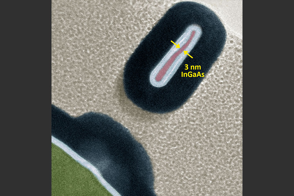
Researchers from MIT and the University of Colorado have fabricated a 3-D transistor that’s less than half the size of today’s smallest commercial models. To do so, they developed a novel microfabrication technique that modifies semiconductor material atom by atom.
The inspiration behind the work was to keep up with Moore’s Law, an observation made in the 1960s that the number of transistors on an integrated circuit doubles about every two years. To adhere to this “golden rule” of electronics, researchers are constantly finding ways to cram as many transistors as possible onto microchips. The newest trend is 3-D transistors that stand vertically, like fins, and measure about 7 nanometers across — tens of thousands of times thinner than a human hair. Tens of billions of these transistors can fit on a single microchip, which is about the size of a fingernail.
As described in a paper presented at this week’s IEEE International Electron Devices Meeting, the researchers modified a recently invented chemical-etching technique, called thermal atomic level etching (thermal ALE), to enable precision modification of semiconductor materials at the atomic level. Using that technique, the researchers fabricated 3-D transistors that are as narrow as 2.5 nanometers and more efficient than their commercial counterparts.
Similar atomic-level etching methods exist today, but the new technique is more precise and yields higher-quality transistors. Moreover, it repurposes a common microfabrication tool used for depositing atomic layers on materials, meaning it could be rapidly integrated. This could enable computer chips with far more transistors and greater performance, the researchers say.
We believe that this work will have great real-world impact,
says first author Wenjie Lu, a graduate student in MIT’s Microsystems Technology Laboratories (MTL).
As Moore’s Law continues to scale down transistor sizes, it is harder to manufacture such nanoscale devices. To engineer smaller transistors, we need to be able to manipulate the materials with atomic-level precision.
Joining Lu on the paper are: Jesus A. del Alamo, a professor of electrical engineering and computer science and an MTL researcher who leads the Xtreme Transistors Group; recent MIT graduate Lisa Kong ’18; MIT postdoc Alon Vardi; and Jessica Murdzek, Jonas Gertsch, and Professor Steven George of the University of Colorado.
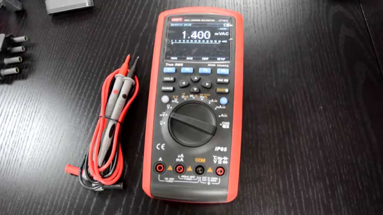
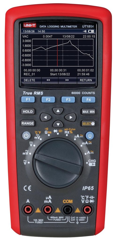
Hand multimeter/ datalogger with 60 000 counts, high precision, comprehensive graphic full-colour display and with the possibility to connect to a PC or a smartphone – that´s the UT 181 A.
If you consider buying a top-class multimeter, probably you already know what you expect of it. Let´s take a look with us at main or most interesting features of the UT 181 A:
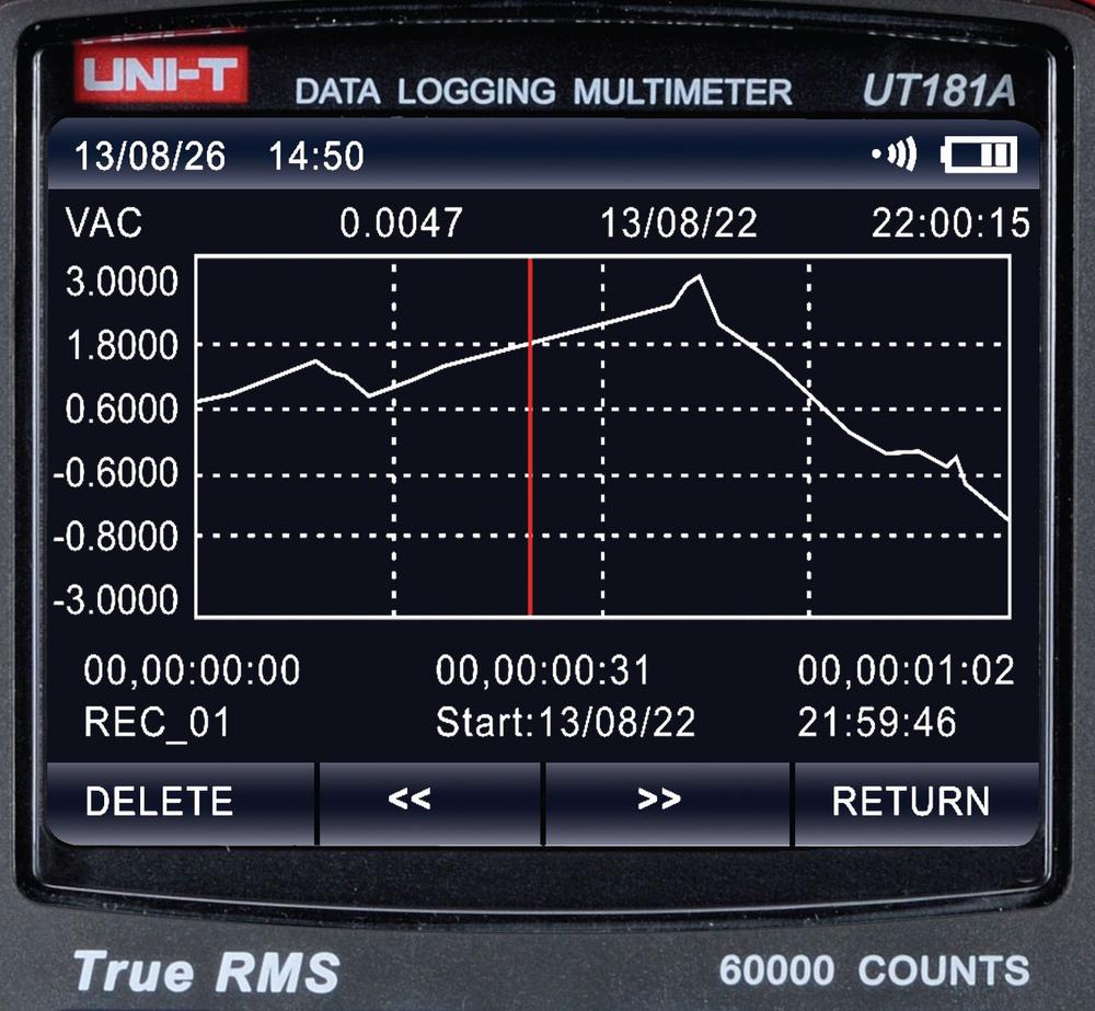
Displaying on a full-colour backlighted TFT display with 320x240px resolution.
Possibility to display measured value graphically (value/ time) as well as numerically.
Memory for 20 000 values (measurings) backed up by a small knob coin battery. User chooses period of measurement, for example 1 second. In this case it means memory for 5,55 hrs of measuring.
High precision and resolution of 60 000 points (0,025% Vdc).
Measuring of capacity with lowest range of 6nF (pF resolution) up to 60mF (miliFarad) on a highest range.
Lowest voltage range only 60mV
True RMS measuring with a possibility to switch on Low Pass filter (1kHz)
Possibility to measure 1000V AC/DC (not only 250-600V as it is common with basic models)
2-channel adapter for temperature measuring (K type thermocouple) on 2 places simultaneously, or to display temperature difference
Optically isolated USB cable for connection with a PC and software on a CD, to display measuring even in real time as well as to read out data from device memory
Powered from a built-in Li-Ion rechargeable battery
Graphic display enables to display, for example maximum, minimum and average value simultaneously. In case of wrong test leads connection, the display shows warning (Load Error). Also pleasant is a really useful fast analogue bargraph. For a demanding outdoor usage, the device features IP65 class.
Optionally the Bluetooth adapter UT-D07 is available, enabling communication with mobile devices (Uni T App). Available on www.soselectronic.com for 265€.
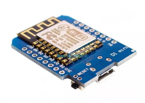
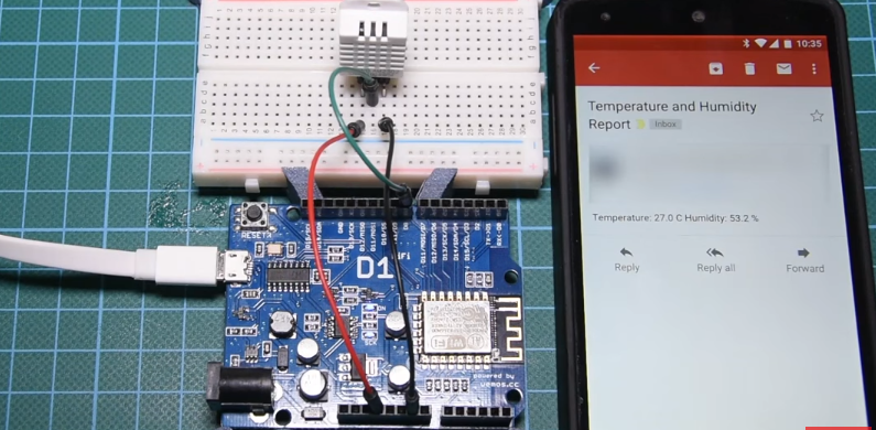
The ESP8266 WiFi module and development boards based on it, enable makers to add an extra layer of intelligence, usefulness, value, and coolness to their creations as it provides an easy and cheap way to build IoT projects. Today’s tutorial will center around sending an email using the ESP8266 as a demonstration of capabilities of this module. The tutorial will be particularly useful if you are building projects that involve alerts and notifications like an intruder alarm system or a gas leakage notification system.
Wemos D1 Mini
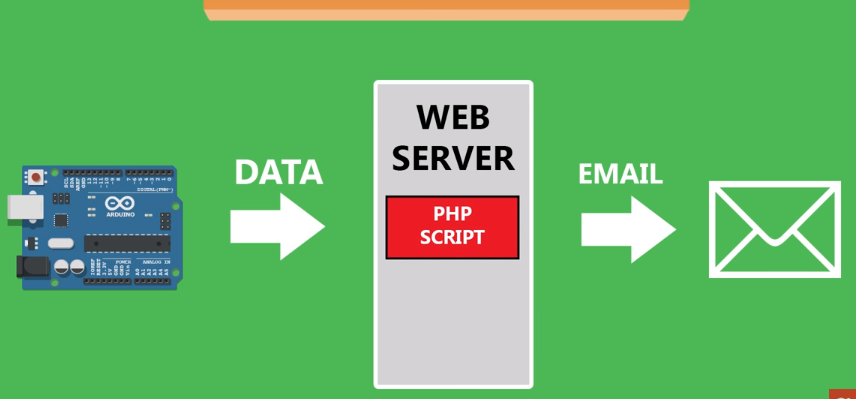
The inspiration for this project is based on the thinking about different ways through which we can get reports from a board. I felt it will be cool if a project could send hourly or per minute reports based on readings from a sensor via email. So for this tutorial, we will connect a DHT22 temperature and humidity sensor to the Wemos D1 (Esp8266 based) board, such that, when the project boots up, it will measure the temperature and humidity and sends the data to a web server hosted on Bluehost. The web server which runs a simple 7-line PHP script, forwards the received data to a predefined email address.
How it works
Instead of using our own web server, we could use an IoT cloud platfrom like adafruit.io and set up an email trigger/alert, but I believe going this route is more effective and flexible as you have full control of the source code.
Require Components
The following components are required to build this project:
The exact components used for this tutorial can be purchased via the links attached to them. It is important to note that any of the Wemos boards listed above will work , so you need just one of the two.
As mentioned above, a web server is also needed for this tutorial. There are several free web hosting platforms available which you can use for this project, but since I already had an account with Bluehost, I decided to go with them.
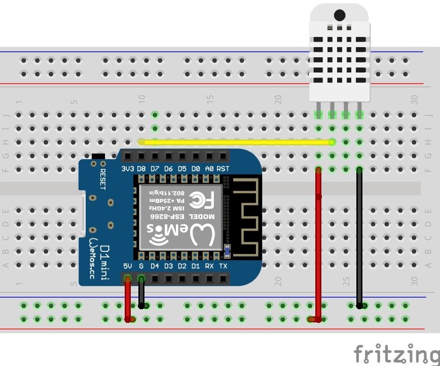
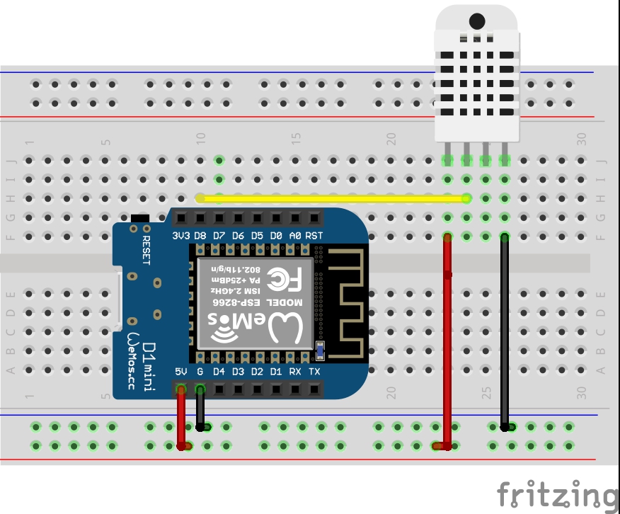
Schematics
The schematic for this project is simple. All we need to do is connect the DHT22 temperature and humidity sensor to the Wemos board. Although the Wemos D1 mini was used for this schematic, you can use any of the other ESP8266 boards available. Connect the components as shown in the schematics below.
Schematic
Here is a breakdown of the connections between the pins to make the connections clearer.
DHT11 – Wemos
VDD – 5v
Data – D8
GND – GND
The connections seems simple enough, but go over it one more time to be sure the wires are properly connected.
Code
There are two parts of the code for this project. The first one is the PHP script which will run on the webserver. This script will take the data sent by the Wemos and forward it to the designated email address.
The second part of code is the Arduino sketch which will run on the Wemos. It will obtain temperature and humidity data from the DHT22 and send it to the Bluehost webserver via a WiFi-based connection.
Arduino Code
We will start with the sketch for the Wemos. If this is the first time you are using the Arduino IDE to program an ESP8266 based board, you will need to download the board support files. This can be easily done using the Arduino board manager, just enter ESP8266 into the search bar and select ESP8266 by the community. Along with the board support files, this will also install a bunch of libraries that may be needed when working with any ESP8266 based board.
The sketch for the Wemos is a simple one. We start by including two important libraries; the ESP8266WIFI.h library and the DHT library. The DHT library makes it easy for us to obtain data from the DHT22 without many lines of code while the ESP8266WIFI.h library makes it easy for us to use the WiFi features of Wemos.
//Written by Nick Koumaris
//info@educ8s.tv

#include <ESP8266WiFi.h>
#include "DHT.h"
After including the libraries, we add the SSID and password of the WiFi network through which the Wemos D1 will connect to the internet and create an instance of the WiFiclient followed by the name/address of the server to which data will be sent.
const char* ssid     = "ZyXEL";      // SSID of local network
const char* password = "YourPasswordGoesHere";   // Password on network
WiFiClient client;
char servername[]="educ8s.tv";  // remote server we will connect to
Next, we declare the variables; temperature, and humidity which we will use to store corresponding data and we specify the pins of the Wemos to which the DHT sensor is connected. We also create an instance of the DHT library with the DHT type and the pin to which it is connected on the Wemos as inputs.
Next is the void setup() function. Since the code is just a demonstration, all the tasks will be performed under the setup function. We initializing communication with the DHT and setting up serial communication between the Wemos and the Arduino serial monitor. With that done, we initiate a connection to the internet via the provided access points and add the code to obtain the data from the DHT using the readsensor() function. The obtained data is then sent to the web server using the sendDataToServer() function.
Next, the email details of the sender and that of the receiver are added after which the email is sent using the mail() function. This takes the sender email, the subject, the body, and the receiver email address as arguments.
Upload the code to the Wemos, after a while, depending on the signal strength of your internet connection, you should get an email notifying you about the current temperature and humidity.
Demo
As mentioned earlier, this can be done using a couple of other methods. We could use MQTT with a cloud platform like adafruit.io or shiftr.io, but this process, is most rewarding due to its low cost and the fact that you have full control on everything.
That’s it for this tutorial, feel free to drop any questions or suggestions about the tutorial under the comment section below.
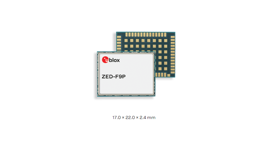
Multi-band GNSS receiver delivers centimeter level accuracy in seconds.
The ZED-F9P positioning module features the new u-blox F9 receiver platform, which provides multi-band GNSS to high volume industrial applications in a compact form factor. ZED-F9P is a multi-band GNSS module with integrated u-blox multi-band RTK technology for centimeter-level accuracy. The module enables precise navigation and automation of moving industrial machinery by means of a small, surface mounted module.
The ZED-F9P module is designed for easy integration and low design-in costs with minimal e-BOM. It is well-suited for mass market adoption, thanks to its small package size, light weight, and small power consumption. ZED-F9P ensures the security of positioning and navigation information by using secure interfaces and advanced jamming and spoofing detection technologies.
ZED-F9P offers support for a range of correction services allowing each application to optimize performance according to the application’s individual need. ZED-F9P comes with built-in support for standard RTCM corrections, supporting centimeter-level navigation from local base stations or from virtual reference stations (VRS) in a Network RTK setup. The module can be upgraded
to support future SSR-type correction services suitable for mass market penetration.
u-blox modules are manufactured in ISO/TS 16949 certified sites and are fully tested on a system level. Qualification tests are performed as stipulated in the ISO16750 standard: “Road vehicles – Environmental conditions and testing for electrical and electronic equipment”. Features
Concurrent reception of GPS, GLONASS, Galileo and BeiDou
Multi‑band RTK with fast convergence times and reliable performance
High update rate for highly dynamic applications
Centimeter accuracy in a small and energy efficient module
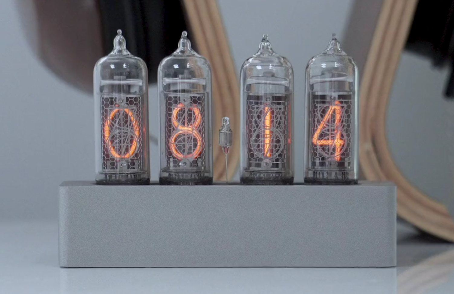
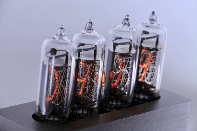
Here at electronics-lab.com we love Nixie clocks and when we came across this beautiful IN-14 clock we thought that worth sharing the news with you. This is a beautifully sleek product that gives new life to vintage components. Argon Prototypes Inc. has launched a kickstarter campaign and it is already funded with 19 days remaining.
At Argon Prototypes we’re obsessed with everything retro – but we also love the practicality, style and technological features of the current day. That’s why our goal was to create a product that combines the undeniable style of vintage Nixie tubes with the appeals of modern technology.
In the development of this product, it was very important for us to create a design as compact and sleek as possible. Through meticulous development of the circuit board design, we are able to offer the Enix in a compact form. This results in a look that is clean, sharp and contemporary, and will look amazing on your desk or bedside table.
Our enclosures are CNC machined from a solid block of 6061 Aluminum and bead-blasted for a smooth satin finish. Every case will be quality-inspected upon production to ensure a high calibre product for all of our backers.
The project is live on kickstarter and pledges start at 329 CA$
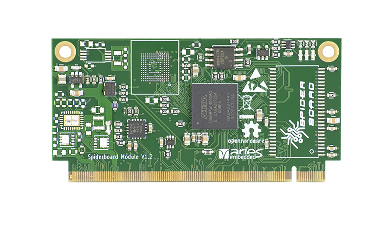
MX10 and SpiderSoM modules are outfitted with a USB device interface, applied with PIC16F1454 microcontroller (MCU). On the SoM side the MCU is connected to three interfaces: serial (if the other side is applied inside the FPGA), an I2C bus (connected to the module PMIC, charge controller, RTC and FPGA), and FPGA JTAG programming interface. The 70mm x 35mm modules support Linux Operating System, but currently, Ubuntu16.04LTS is marked as a reference base.
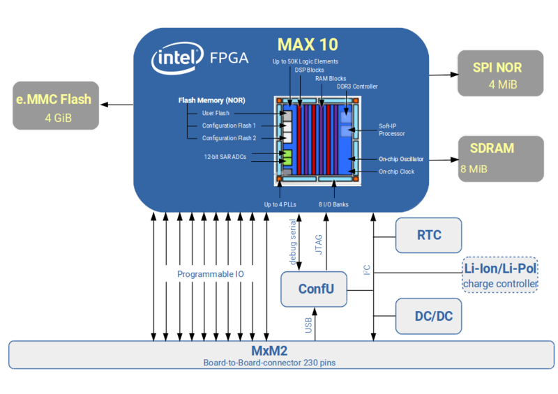
The modules feature a programmable clock generator and PLL, with optional external reference input. Available also are 178 FPGA GPIO pins, including 13 LVDS transmitters and 54 receivers. optional 128/256/512MByte DDR3 DRAM (for 10M 16/25/40/50 FPGAs) is also available. Programmable high-efficient PMIC, FPGA IO voltages are configurable for user convenience. The modules support a wide range of devices: from 10M04DC to 10M50DA. Other features include an optional Li-Ion/Li-Pol charger, RTC with battery backup, optional 4 GByte e.MMC, optional 4 MByte SPI NOR, optional 8 MiB SDRAM, and a MAX 10 FPGA in F256 package. The SpiderSoM is a programmable, non-volatile solution based on Intel®️ MAX®️10 FPGA, which allows it to produce full-featured FPGA capabilities.
SpiderSoM Block Diagram
The SpiderSoM can function with the standard baseboard (SpiderBase) as a total building block or can be plugged into an existing design and products as a functional part. It links to its baseboard via a 230pins MXM2 connector and gives the proper results for various soft-core CPUs, video-processing algorithms, etc. The SpiderSoM is a low cost and highly flexible platform which allows users to set up a running system according to the required specification in a very short time frame. SoM is modeled on the free and open design concept: KiCAD design files and schematics are available under CERN OHL v1.2. The MX10 SoM targets the aspect of professional electronic designs in commercial applications, while the SpiderSoM, on the other hand, was designed to be used in IoT Maker applications.
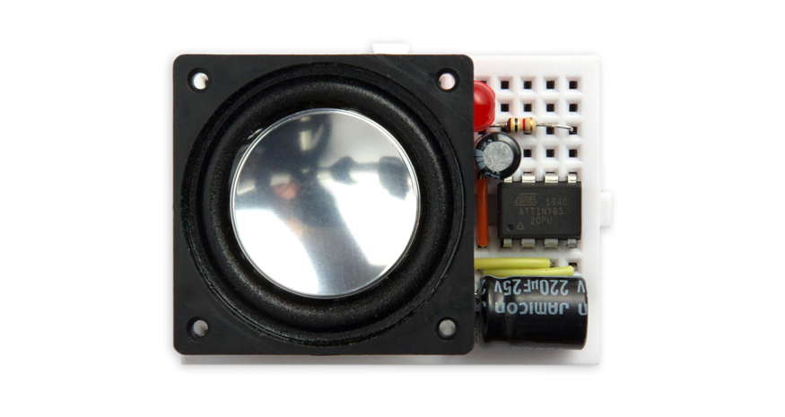
David Johnson-Davies published another tiny project. This is an ATtiny85-based digital music box that will play a tune stored in memory in MIDI format:
The notes sound like a music box or harpsichord, with a decaying envelope, and there are four channels, so up to four notes can play simultaneously. My demonstration program plays the Bach Fugue in D Minor; here’s what it sounds like: midiplayer.mp3
You can easily program it to play any MIDI music-box tune you like, from a site such as Music Box Maniacs, and you could use it as the basis for an electronic greeting card, a musical marriage proposal ring box, an electronic doorbell, or any other music-based project.
New co-authored paper demonstrates potential ten-fold energy density increase over existing lithium-ion battery technologies.
Scientists from Honda Research Institute have collaborated with researchers at California Institute of Technology (Caltech) and NASA’s Jet Propulsion Laboratory to develop a new battery chemistry that enables the use of materials with higher energy density and a more favorable environmental footprint than current battery technologies. The collective team of scientists co-authored a new paper on the topic that was published in Science and is available at http://science.sciencemag.org/cgi/doi/10.1126/science.aat7070.
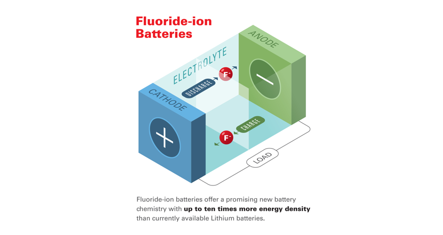
The joint study reports that the research team has opened new doors in the development of high energy-density batteries capable of meeting rapidly growing energy storage needs by overcoming the current temperature limitations of fluoride-based battery (FIB) technology and by demonstrating the room-temperature operation of fluoride-ion based energy cells.
Fluoride-ion batteries offer a promising new battery chemistry with up to ten times more energy density than currently available Lithium batteries,
said Dr. Christopher Brooks, Chief Scientist, Honda Research Institute, and a co-author of the paper.
Unlike Li-ion batteries, FIBs do not pose a safety risk due to overheating, and obtaining the source materials for FIBs creates considerably less environmental impact than the extraction process for lithium and cobalt.
FIBs provide an attractive alternative to other types of potential high-energy battery electrochemistries, such as those based on lithium- or metal hydride chemistries, which are generally limited by the inherent properties of their electrodes. Due to the low atomic weight of fluorine, rechargeable batteries based on the element could offer very high energy densities–up to 10 times greater than the theoretical values for lithium-ion technologies. However, while FIBs are considered a strong contender for the “next-generation” of high-density energy storage devices, they are limited by their required temperature requirements.
Currently, solid-state fluoride ion-conducting battery iterations need to operate at elevated temperatures–above 150 degrees Celsius–to make the electrolyte fluoride-conducting. According to the paper’s authors, these limitations in the electrolyte have presented a significant challenge for achieving low-temperature operating FIBs.
To address this, the research team found a method for creating a fluoride-ion electrochemical cell capable of operating at room temperature–a breakthrough made possible by a chemically stable liquid fluoride-conducting electrolyte with high ionic conductivity and a wide operating voltage. The scientists developed the electrolyte using dry tetraalkylammonium fluoride salts dissolved in an organic, fluorinated ether solvent. When paired with a composite cathode featuring a core-shell nanostructure of copper, lanthanum and fluorine, the researchers demonstrated reversible electrochemical cycling at room temperature.
In the future, FIBs could power battery-electric vehicles. The higher-capacity nature of the battery makes it a good candidate for power products as well.
One thing about microcontrollers that will always be respected, is their ability to consistently provide real-time processing, low power, low cost, and most importantly a lot of I/Os. They excel quite well in those aspects, and in some cases they are indisputable, but when we deal with security and user interface comes into play, this is usually out of the question and designers usually result to an application processor which provides extreme performance but might also have some drawbacks.
How do we bring the best of both worlds together? Bridge the gap between performance and usability? Well, NXP launched the i.MX RT Series Crossover Processor family. The i.MX RT Series is the industry’s first crossover processor, offering the highest performance Arm®Cortex®-M core, real-time functionality, and MCU usability at an affordable price. A real-time response with latency as low as 20ns is what you get with these crossover processors.
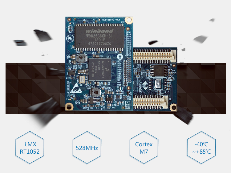
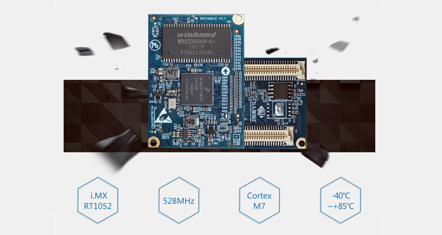
The Forlinx Embedded OK1052-C board is a production-ready commercial solution that leverages the NXP i.MX RT series crossover processors. At the core of the Forlinx OK1052 is the NXP Cortex-M7 crossover processor i.MX RT1052 belonging to i.MX RT1050 series MCU. The i.MX RT1050 runs on the Arm®Cortex®-M7 core at 600 MHz with insane real-time response. The i.MX RT1052 processor has 512 KB on-chip RAM, which can be flexibly configured as TCM or general-purpose on-chip RAM. 16MB/ 32MB SDRAM, 4MB/ 16MB QSPI-NorFlash are optional.
Forlinx Embedded OK1052-C comes available as system-on-module and carrier board. They are both ready to be deployed in any terrain, capable of working in temperature ranges from -40℃ to +85℃ making in usable in the industry.
Forlinx OK1052-C SoM
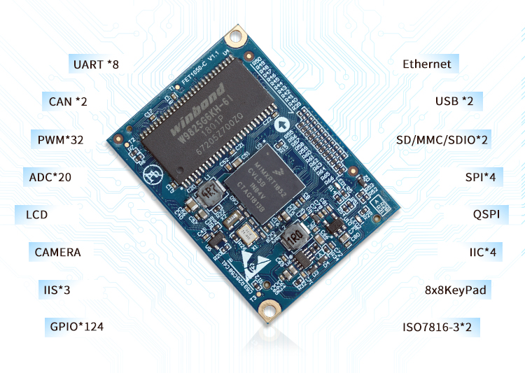
Below are the SOM (FET1052-C SoM) specifications:
SoC – NXP i.MX RT1052 single core Arm Cortex-M7 crossover processor @ up to 528 MHz with 512KB SRAM/TCM
System Memory – 16MB or 32MB SDRAM
Storage – 4MB to 16MB QSPI Nor Flash
Board to board connectors – 2x 80-pin connectors with 0.8mm pitch:
Display – 1x RGB888 LCD interface up to 1366×768 resolution
Camera – 8-bit DVB interface for a 5MP camera
Storage – Up to 2x SD or SDIO card with 1-bit or 4-bit mode
Audio – Up to 3x I2C, 1x S/PDIF
Networking – 1x 10/100Mbps Ethernet
Up to 8x UART, up to 4x host/device SPI interfaces, up to 4x I2C
Up to 32x PWM, up to 2x CAN 2.0B buses
2x 12-bit ADC up to 20 channels
8×8 keypad
Up to 2x ISO7816-3 interfaces for smart cards
1x 16-bit parallel SEMC (Smart External Memory Controller) bus
Supply Voltage – 5V
Dimensions – 43 x 31 x 1.6 mm (4-layer PCB)
Temperature Range – -40 to +85°C
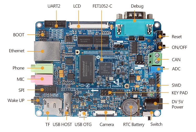
Forlinx OK1052-C Carrier Board
The OK1052-C Carrier Board extends out most of the device peripherals out. Below are its specifications:
Storage – Micro SD card slot, 256 bytes EEPROM
Display
LCD RGB565 I/F up to 1366×768 resolution
Resistive touch via TSC2007 chip, 4x ADC
PWM for LCD backlight
Camera – 8-bit DVP connector for 5MP camera
Audio – 3.5mm microphone and earphone jacks
Networking – 100Mbps Ethernet (RJ45)
USB – 1x USB host port, 1x micro USB OTG port
Expansion
10-pin UART2 header, a 10-pin SPI header, 8-pin keypad header; all 2.54mm pitch
CAN bus screw terminal
Resistor adjustable ADC
Debugging – RS232 DB9 connector for serial debugging, 8-pin SWD debug port
Misc – RTC + battery slot; 1x user LED; reset, wake-up and power buttons, power switch, BOOT DIP switch for booting mode selection
Power Supply – TBD via power barrel jack
The board supports uClinux, Keil IAR, ARM-GCC tools, FreeRTOS, ARM mbed, and some other related development tools. It’s believed that Forlinx Embedded provides both MCU code samples and uClinux BSP with demos for all main functions of the board to their customers.
Although the module and carrier board are available for purchase, their prices are currently not being disclosed publicly, and you will have to contact them for purchasing information and support. More information is available on the product page.
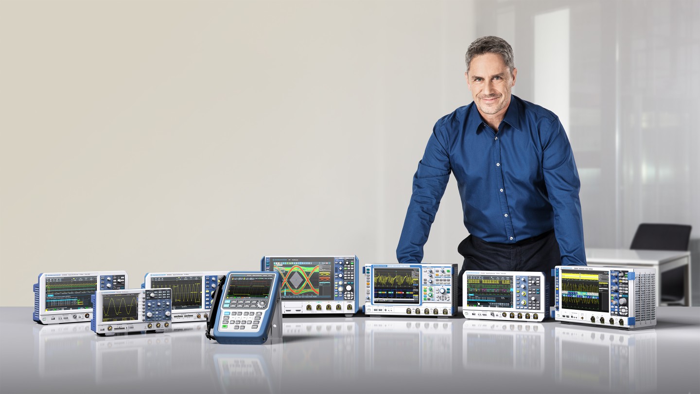
Rohde & Schwarz is again expanding its oscilloscope portfolio with the launch of the R&S®RTC1000, R&S®RTM3000 and R&S®RTA4000 series oscilloscopes. With this market introduction Rohde & Schwarz has now the most up-to-date 1000, 2000, 3000 and 4000 class instruments on the market.
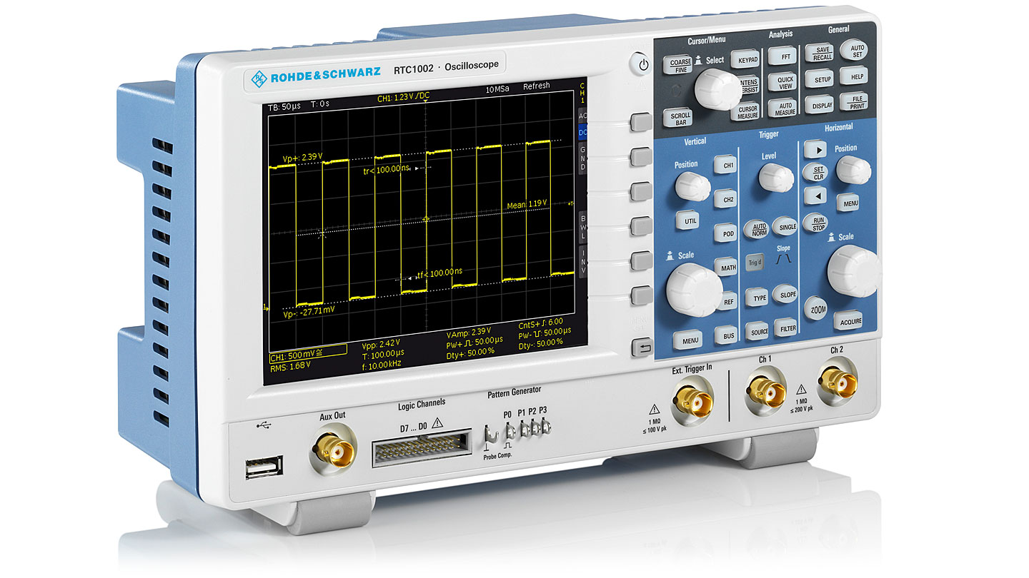
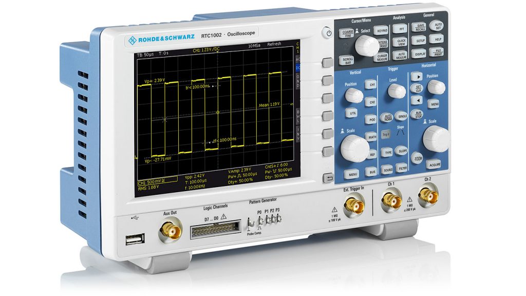
R&S®RTC1000 oscilloscope
The new R&S®RTC1000 series oscilloscope features the highest instrument integration in its compact form factor. Starting at a price of EUR 835, the instrument’s comprehensive features are tailored to meet the needs of users in the field of education, engineers with low budgets and hobbyists.
R&S®RTC1000 oscilloscopes are available in models from 50 MHz to 300 MHz. They are the first in the 1000 class to offer bandwidth upgrades via software license all the way to 300 MHz bandwidth; these upgrades can be purchased as test needs increase over time. The two-channel oscilloscopes have maximum sample rates of 2 Gsample/s and a memory depth of 2 Msample.
All R&S®RTC1000 models come as standard with LAN and USB interfaces.
R&S®RTM3000 oscilloscope
Get in touch with the new R&S®RTM3000 and R&S®RTA4000 series oscilloscope
The new R&S®RTM3000 oscilloscope offers bandwidths of 100 MHz, 200 MHz, 350 MHz, 500 MHz and 1 GHz. The products incorporate a proprietary 5 Gsample/s 10-bit ADC, and each model includes 40 Msample (80 Msample interleaved) per channel acquisition memory with an optional 400 Msample segmented acquisition memory.
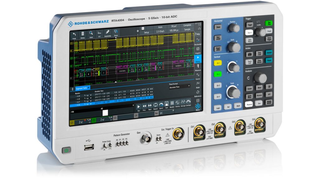
The new R&S®RTA4000 oscilloscope offers bandwidths of 200 MHz, 350 MHz, 500 MHz and 1 GHz. These models include the same 10-bit ADC, but have even more memory, with an astonishing 100 Msample (200 Msample interleaved) per channel acquisition memory and standard 1 Gsample (1,000 Msample) segmented acquisition memory. Both instrument series feature a brilliant 10.1″ capacitive touchscreen display to operate quickly and efficiently. Starting at 3.190EUR
R&S®RTA4000 oscilloscope
While the R&S®RTM3000 series comes in two- and four-channel models, the R&S®RTA4000 series oscilloscopes are exclusively four-channel models. Base prices start at EUR 3,190 for the two-channel 100 MHz R&S®RTM3002. The four-channel 200 MHz R&S®RTA4004 starts at EUR 5,230. For users with more demanding needs, a number of upgrade options are available. These include 16 integrated digital channels with a mixed signal oscilloscope (MSO) option, protocol decode and triggering options for a variety of industry standard buses as well as an integrated waveform generator.