While IoT is awesome, there are situations where we do not necessarily want to connect the devices to the internet but connect them together. It could be a need for a local network of sensors to monitor certain parameters on a farm for instance. This kind of project will involve a base station connected wirelessly to sensors in the field. For today’s tutorial, we will demonstrate something similar to this scenario by building a wireless weather station with a remote sensing unit and a base station where the data is gathered.
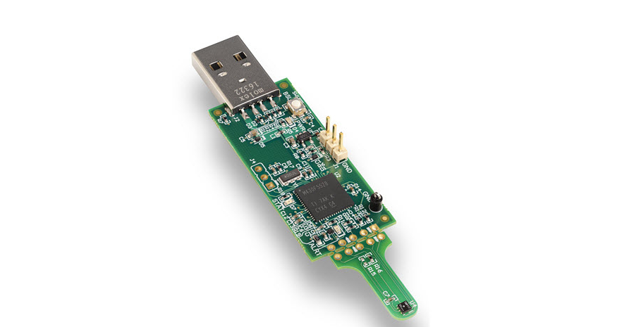
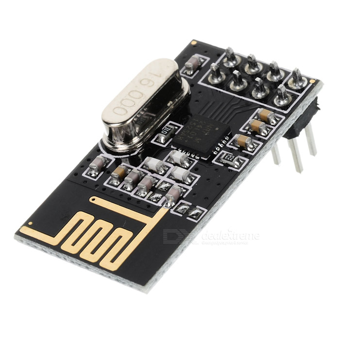
For this tutorial, we will use the NRF24L01 low-cost (less than$3) ultra-low power, bi-directional transceiver module to communicate between the base station and the remote sensing unit. It is designed to operate within the 2.4GHz ISM band which means it can be used for projects with industrial, scientific and medical applications. The module can achieve data rates as high as 2Mbits! and uses a high-speed SPI interface in order to communicate with the Arduino or other microcontrollers/development boards.
As mentioned earlier, there are two parts to this project. The first one is the remote sensing unit which can be placed anywhere within the range 0f the NRF module. The remote sensing unit is made up of an Arduino Nano, a DHT22 temperature and humidity sensor and the NRF24L01 wireless transceiver module. It senses temperature and humidity from the environment every second and sends it via the NRF24L01 module to the base/monitoring station.
The second part is the base/monitoring station. The base/monitoring station receives weather data from the remote sensing unit and displays it on the attached 3.2″ Color TFT display. The station is built using the fast 32bit Arduino Due, a 3.2” Color TFT display, DS3231 real-time clock module, the NRF24L01 and a DHT22 temperature and humidity sensor which is used to determine temperature and humidity within the vicinity of the base/monitoring station. Asides the temperature and humidity from both the remote sensing unit and the DHT22 attached to the base station, the station also displays the current time and date sourced from the attached ds3231 RTC module. The data from the remote sensing unit is received by the base station every second to ensure a reliable communication link is established between the base station and the remote sensing unit.
At the end of this tutorial, you will know how to build a wireless weather monitoring station and how to use the NRF24L01 transceiver to send data between two Arduinos.
Required Components
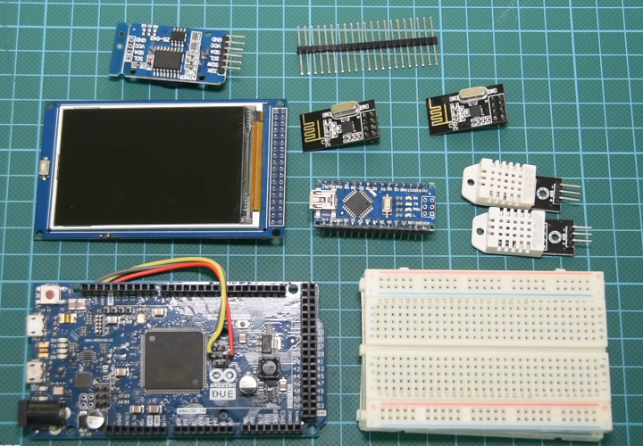
The following components are required to build this project;
- Arduino Due
- Arduino Nano
- 3.2″ TFT display
- DHT22
- NRF24L01
- DS3231 RTC
- Small Breadboard
- Wires
- Header Pins
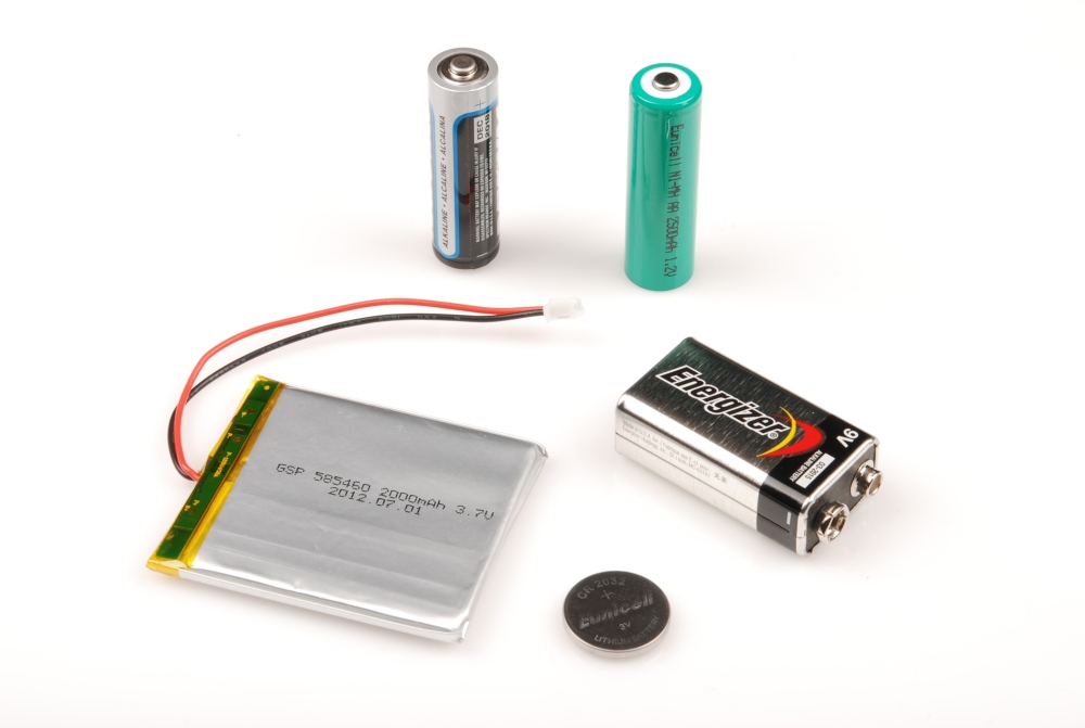
- Xiaomi Powerbank
As usual, you can click on the links attached to each of the components to buy the exact one that was used for this tutorial.
Schematics
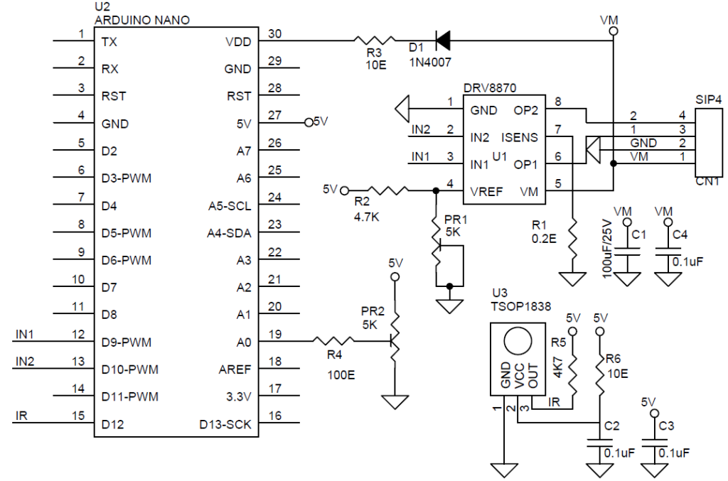
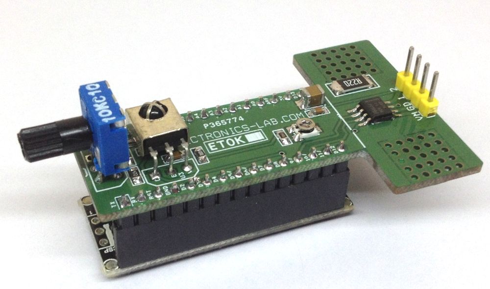
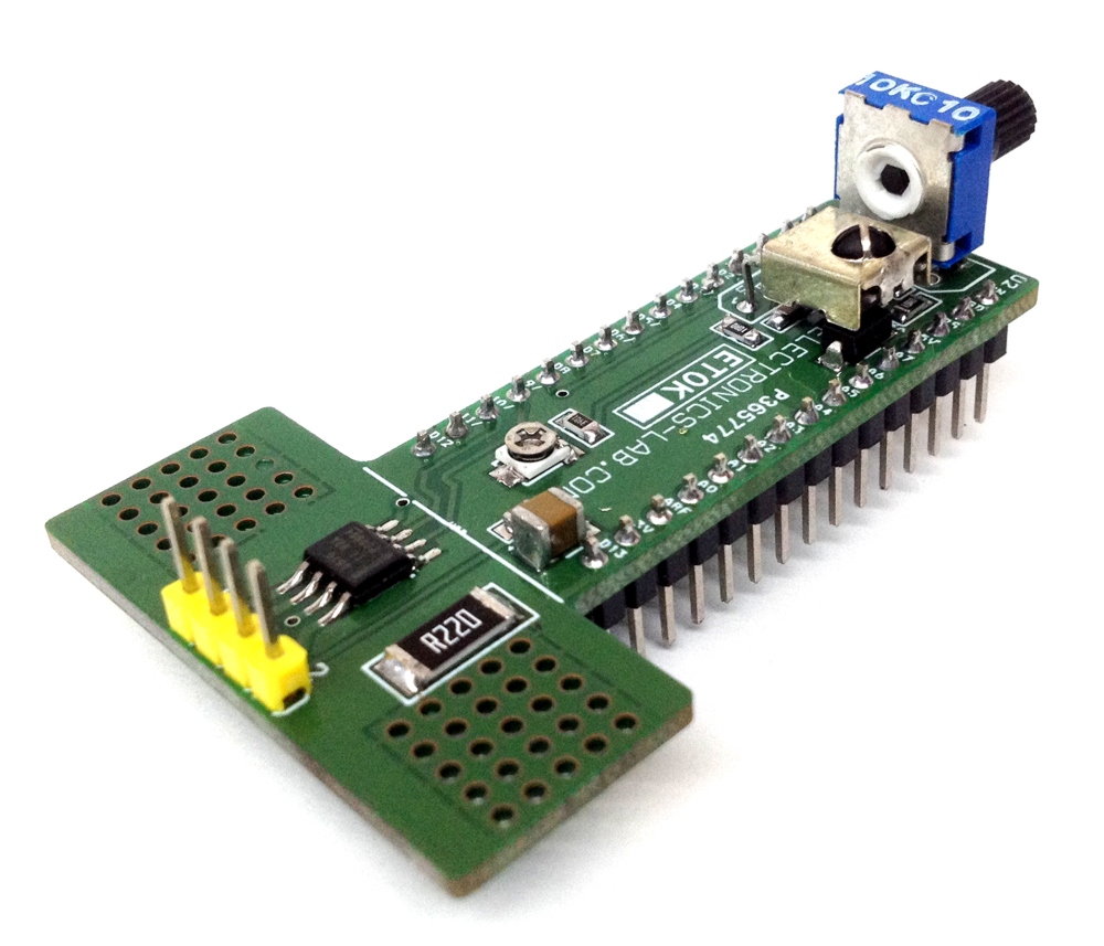
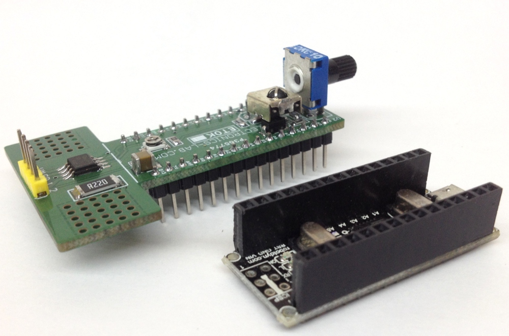
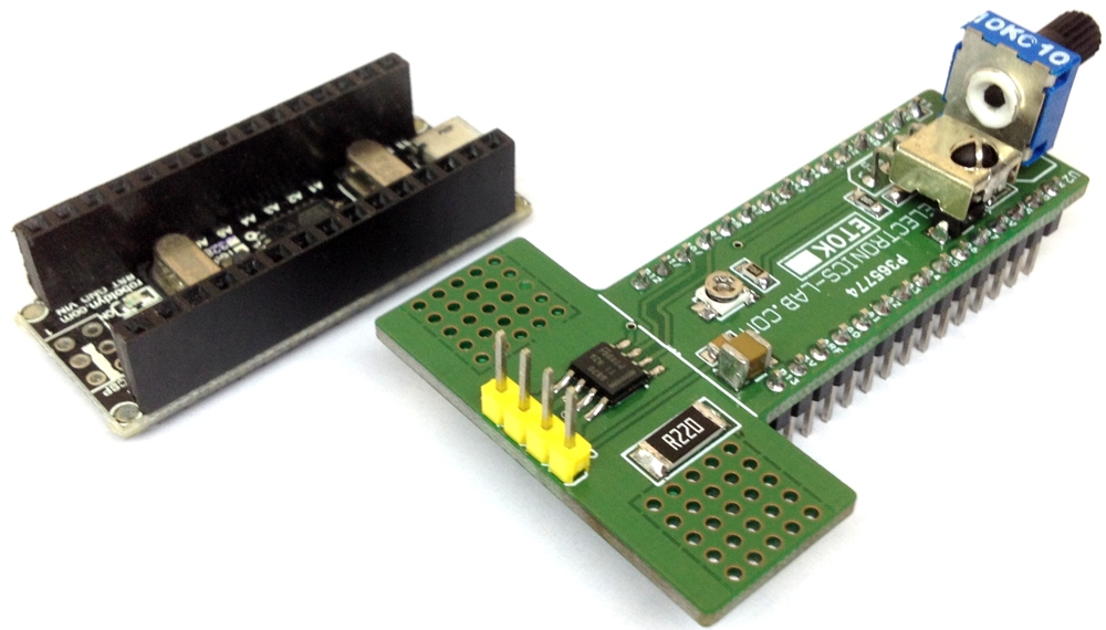
There are two schematics for this project. The first one is for the transmitter (i.e the remote sensing unit). As mentioned earlier, the remote sensing unit is made up of the DHT22, the NRF24L01 and the Arduino. Connect them as shown in the schematics below.
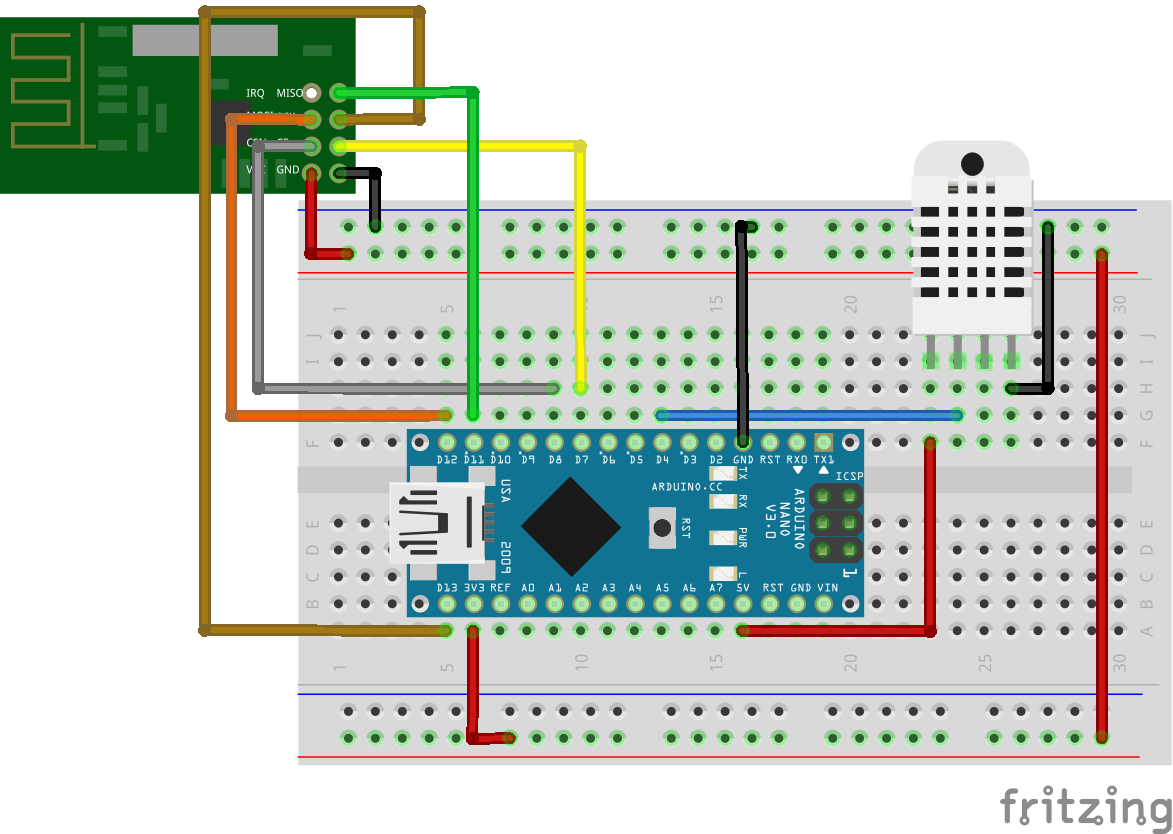
To make the schematics easier to follow, here is a map of the connections of between the Arduino and the other components.
NRF24L0 – ARDUINO NANO
GND - GND
VCC  - 3.3V
CE - D7
CS - D8
SCK - D11
MOSI - D12
MISO - D13
DHT22 ARDUINO NANO
VCC - VCC
GND - GND
DATA -  D4
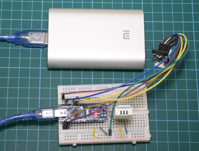
Note that the VCC pin of the NRF24L01 module was connected to the 3.3V pin of the Arduino, not 5V. A picture of the transmitter’s schematics implementation is shown below.
The second schematic is that of the receiver (i.e the base/monitoring station). The 3,2″ TFT display used in this tutorial comes as a shield so all we need to do is to mount it on the Arduino. Asides this and the real-time clock, the connection of the receiver is quite similar to that of the transmitter. Connect the components as shown in the schematics below.
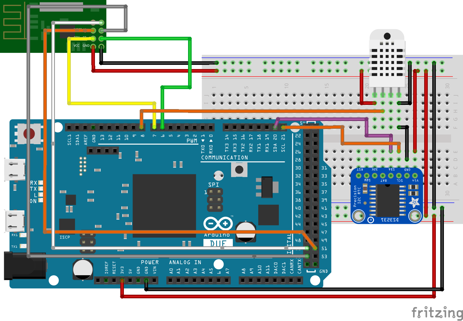
As usual, the connections between the Arduino and the other components is further described below to make the schematics easier to follow.
NRF24L01 – ARDUINO DUE
VCC - 3.3V
GND - GND
CE - D6
CS - D7
SCK - 52
MOSI - 51
MISO - 50
DHT22 – ARDUINO DUE
VCC - VCC
GND - GND
DATA - D8
DS3231 – ARDUINO DUE
VCC - VCC
GND - GND
SDA - SDA
SCL - SCL
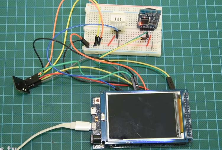
A picture of the receiver’s schematic implementation is shown below.
Go over the connections once again to be sure everything is as it should be before proceeding to the next section. To better understand how to use the NRF24L01 module with the Arduino, you can check out one of our previous tutorials here.
Code
Just like we had with the schematics, we have two Arduino sketches for this project. One of them will be for the transmitter while the other one will be for the monitoring station.
We start with the code of the transmitter, as usual, by including the libraries that will be used for the project, which in this case are the RF24 library (for the NRF24L01), the DHT22 Library and the SPI library. The SPI library is included in the Arduino IDE while the rest can be downloaded via the links attached to them. With the libraries included, we declare the pins of the Arduino to which our DHT is connected and create an instance of the RF24 library stating the pins of the Arduino to which the CE and CS pins of the NRF are connected.
//Written by Nick Koumaris
//Info@educ8s.tv
#include "DHT.h"
#include <SPI.h>
#include "RF24.h"

#define DHTPIN 4
#define DHTTYPE DHT22

RF24 myRadio (7, 8);
byte addresses[][6] = {"0"};
const int led_pin = 13;
Next, we create a struct package for organizing the data into packets to be sent by the NRF, after which we create an object of the DHT class passing the pin of the Arduino to which DHT pin is connected and the DHT TYPE as arguments.
struct package
{
  float temperature ;
  float humidity ;
};
typedef struct package Package;
Package data;
DHT dht(DHTPIN, DHTTYPE);
We proceed to the void setup() function. Here we initiate serial communication and also initialize DHT and NRF modules, setting the communication channel, signal power, and the data rate of the NRF.
void setup()
{
    Serial.begin(9600);
    pinMode(led_pin, OUTPUT);
    dht.begin();
    myRadio.begin();
    myRadio.setChannel(115);
    myRadio.setPALevel(RF24_PA_MAX);
    myRadio.setDataRate( RF24_250KBPS ) ;
    myRadio.openWritingPipe( addresses[0]);
    delay(1000);
}
Finally, the loop() function. Here we read the values of temperature and humidity from the DHT and send it to the receiver using the NRF24L01. To show if there is a valid transmission, a LED connected to pin 13 is blinked.
void loop()
{
  digitalWrite(led_pin, HIGH); // Flash a light to show transmitting
  readSensor();
  Serial.println(data.humidity);
  Serial.println(data.temperature);
  myRadio.write(&data, sizeof(data));
  digitalWrite(led_pin, LOW);
  delay(1000);
}
that’s it for the transmitter. The complete code is shown below.
//Written by Nick Koumaris
//Info@educ8s.tv
#include "DHT.h"
#include <SPI.h>
#include "RF24.h"

#define DHTPIN 4
#define DHTTYPE DHT22

RF24 myRadio (7, 8);
byte addresses[][6] = {"0"};
const int led_pin = 13;

struct package
{
  float temperature ;
  float humidity ;
};


typedef struct package Package;
Package data;

DHT dht(DHTPIN, DHTTYPE);

void setup()
{
    Serial.begin(9600);
    pinMode(led_pin, OUTPUT);
    dht.begin();
    myRadio.begin();
    myRadio.setChannel(115);
    myRadio.setPALevel(RF24_PA_MAX);
    myRadio.setDataRate( RF24_250KBPS ) ;
    myRadio.openWritingPipe( addresses[0]);
    delay(1000);
}


void loop()
{
  digitalWrite(led_pin, HIGH); // Flash a light to show transmitting
  readSensor();
  Serial.println(data.humidity);
  Serial.println(data.temperature);
  myRadio.write(&data, sizeof(data));
  digitalWrite(led_pin, LOW);
  delay(1000);
}

void readSensor()
{
 data.humidity = dht.readHumidity();
 data.temperature = dht.readTemperature();
}
For the receiver, we will use the RTC library and the Modified Adafruit TFT LCD library in addition to the ones used for the transmitter.
After installing the libraries, the code starts the same way as that of the transmitter. We include the libraries, create objects of the libraries specifying the pin of the Arduino to which the components are connected and create variables that will be used in the code.
//Written by Nick Koumaris
//info@educ8s.tv

#include <TFT_HX8357_Due.h> // https://github.com/Bodmer/TFT_HX8357_Due
#include <Sodaq_DS3231.h>  //RTC Library https://github.com/SodaqMoja/Sodaq_DS3231
#include "DHT.h"          //https://github.com/adafruit/DHT-sensor-library
#include "RF24.h"        //https://github.com/TMRh20/RF24

#define DHTPIN 8

#define DHTTYPE DHT22
DHT dht(DHTPIN, DHTTYPE);

RF24 myRadio (6, 7);
byte addresses[][6] = {"0"};

TFT_HX8357_Due tft = TFT_HX8357_Due();       // Invoke custom library

float remoteHumidity = 0.0;
float remoteTemperature = 0.0;

String dateString;
String hours;
int minuteNow=0;
int minutePrevious=0;
Next, we create the struct package to receive the data sent from the transmitter.
struct package
{
  float temperature ;
  float humidity ;
};
The setup() function is next. We initialize the DHT, RTC and the display, setting the desired orientation for the screen and calling the function to display the User interface created to display the data in a nice way. After this, we connect to the transmitter using the START communication function.
void setup() {

  Serial.begin(9600);

  tft.init();
  tft.setRotation(1);
  tft.fillScreen(TFT_BLACK);
  delay(100);

  rtc.begin();
  dht.begin();
  delay(2000);
  //setRTCTime();

  startWirelessCommunication();
  printUI();
}
Next is the loop() function. We start by checking if data is sent after which we display the time, date, indoor temperature, indoor humidity, and the temperature and humidity from the remote sensing unit (outdoor). Other functions were used to make the code readable.
void loop() {

   checkForWirelessData();

   getAndPrintTime();

   printIndoorTemperature();
   printIndoorHumidity();

   printRemoteTemperature();
   printRemoteHumidity();
}
The complete code for the receiver is quite large. It is attached under the download section below along with the code for the transmitter.
Demo
Copy/download the code and upload to the corresponding Arduino setup. Go through each of the hardware setups carefully before plugging the Arduino board to be sure there is no short circuit and that everything is properly connected. With this done, connect the board and upload the code. You should see the Screen come up as shown in the image below.
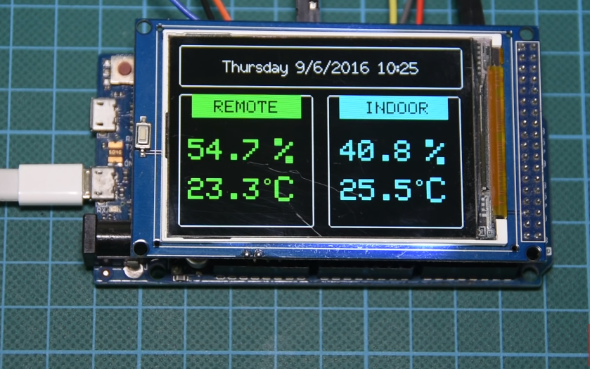
To reduce the amount of time the screen is refreshed and to avoid flickers, the receiver checks if there is a difference between the last received temperature or humidity value before updating the display. If there is a difference, the display is updated, but if the values are the same, the screen is left unchanged.
That’s it for this tutorial guys, thanks for reading. If you have any question or comments, do drop them under the comments section below.
Till next time!
The video version of this tutorial is available on youtube.