Intel launched the Neural Compute Stick back in 2017, and now the Neural Compute Stick 2 was announced in Beijing in November this year which promises almost 20x the power of the Stick 1. Also, Intel isn’t the only one launching or building something related to AI sticks, Gyrfalcon also introduced their Laceli AI Compute Stick and now the latest member to get on this wagon is the Orange Pi AI Stick from Shenzhen Xunlong Software, the Orange Pi boards maker.
We are entering into the era of AI inference at the edge for low power consumptio. The need for developing AI-powered applications for IoT devices and similar is growing without necessarily sacrificing power or cost. Orange Pi which has been widely known for its Raspberry Pi replication boards has recently launched the Orange Pi AI Stick 2801 which is based on the Lightspeeur 2801S ASIC processor.
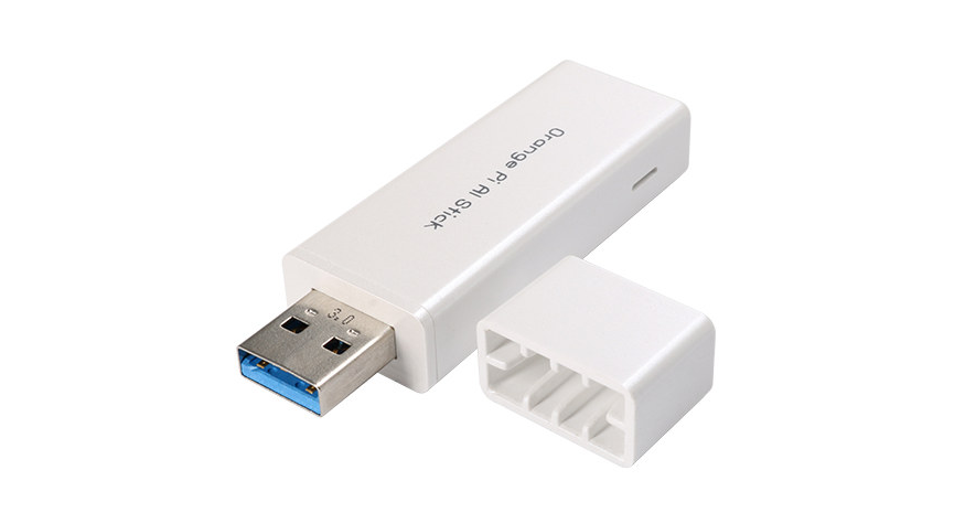
The built-in Lightspeeur® optical spear SPR2801AI chip allows Orange Pi AI stick to run machine learning and real-time deep learning directly on the device and just like the Intel Stick, the Orange Pi stick is geared towards image, video, voice, and natural language recognition.
Temperature Range – working: 0 to 40°C; storage: -20 to 80°C
Dimensions – 66.5 mm x 20.5 mm x 10.8 mm
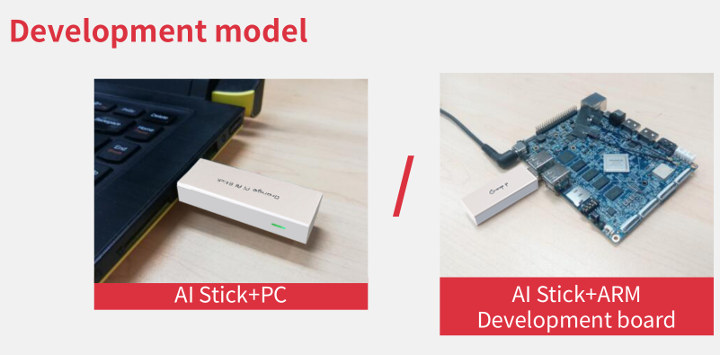
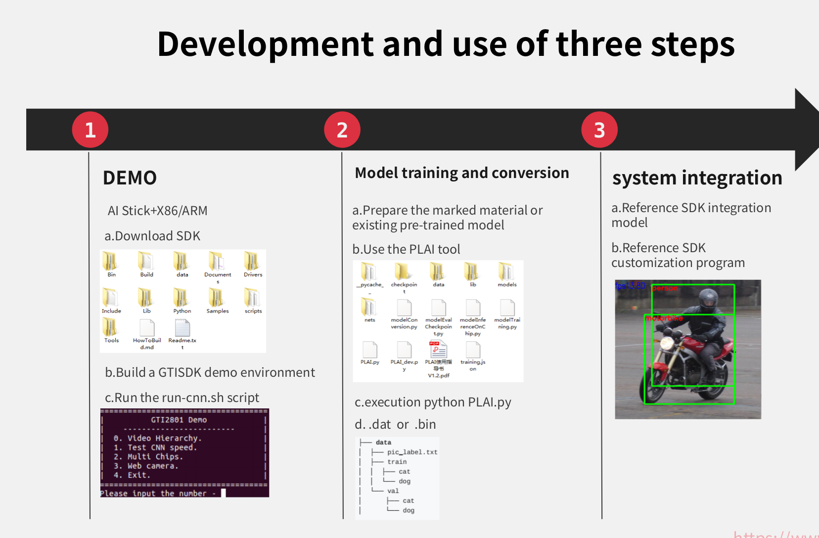
An SDK and user manual has been released for the Orange Pi AI Stick for x86 PC and pre-trained models with some sample cat/dog data. Planning on training your own model and data, you will get set back by an additional $149 for the PLAI model transformation and training tools. The Orange PI AI stick costs $69 alone and can be purchased from Aliexpress. The Stick plus PLAI tools costs $218 and also available for purchase on Aliexpress. PLAI stands for People Learning Artificial Intelligence and is an ecosystem of hardware and tools provided directly by Gyrfalcon, the ASIC vendor.
Below are some exciting applications for the Orange Pi AI sticks:
Moving edge calculation
Intelligent monitoring
Smart toys, smart homes, and robots
Virtual reality and augmented reality
Face detection and recognition
Speech Recognition and Natural language processing
Artificial intelligence data center server
Advanced assisted driving and autonomous driving
The stick will provide support for use with Caffe and Pytorch frameworks, but no support is available for Tensorflow currently. The device is recommended to be used with a host device running Ubuntu 16.04 with at least 2GB RAM, and 4GB flash. At 2GB RAM a lot of SBCs might fall short of using this stick.
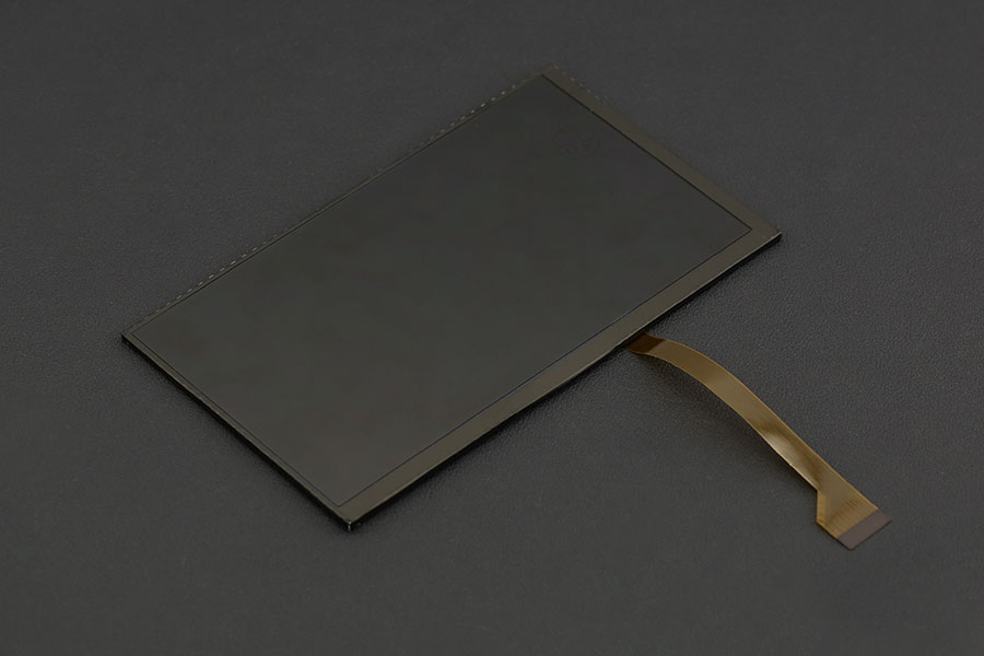
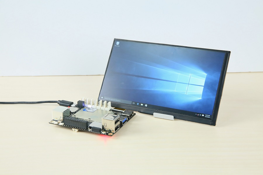
Add exciting new dimensions to your project with this large full-color display. All you need to do is power your LattePanda single board computer and you have a visual user interface for your project – no extra power cables required! The border of the display is insulated with black tape so that even without and enclosure there is no possibility of a short-circuit. The picture below shows a LattePanda directly powering the 7″ display.
Note: LattePanda uses a custom MIPI pinout that will not be compatible with alternative IPS displays! You can still use HDMI out. Use your display in conjunction with the capacitive touch panel (not included) to get a touch interface for your project! NOT compatible with LattePanda Alpha and Delta edition
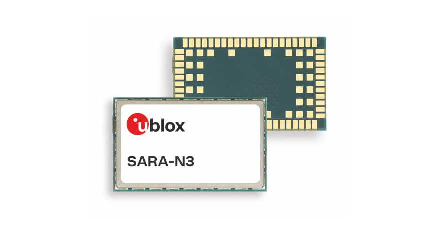
u-blox, a global provider of leading positioning and wireless communication technologies, has announced the SARA-N3, a multi-band NB-IoT module that supports a preliminary set of 3GPP Release 14 features (LTE Cat NB2). The SARA-N3 is available in two variants: one dedicated to China and another that can operate across multiple bands on any NB-IoT network globally.
The u-blox firmware-over-the-air (uFOTA) client/server solution with Lightweight M2M (LwM2M) allows SARA-N3 to be remotely provisioned with additional features. LwM2M is a more lightweight solution as compared to OMA-DM and thereby ideal for providing critical firmware updates to IoT devices. In this way, SARA-N3 can ultimately become 5G compliant. SARA-N3 also supports the creation of dynamic LwM2M objects, giving customers high levels of feature customization through the ability of scripting their own configurable objects.
With its feature-rich capabilities, the SARA-N3 enables the development of one device across multiple regions for a wide variety of IoT/IIoT applications such as metering, smart city smart city systems, smart homes and industrial trackers,
says Samuele Falcomer, Senior Product Manager, Product Center Cellular at u-blox.
For customers currently using other methods to send IoT/IIoT data, such as legacy cellular technology, it is simple to upgrade to SARA-N3 through u-blox nested design and the new features introduced. The product is future-proof, as it can receive further firmware upgrades over the air.
The SARA-N3 provides a comprehensive set of features and protocols that NB-IoT-based applications will benefit from, including TCP, HTTPS, CoAP, DTLS and MQTT. With its ultra-low power consumption profile and the ability to configure voltage domains, the module is optimized to operate on a single cell primary battery for 10+ years, eliminating the need for frequent maintenance visits. Other features include a ‘last gasp’ function that lets the module send one last message should the power fail unexpectedly and protection against software attacks by detecting potential jamming signals.
u-blox manufactures according to ISO/TS16949 professional grade specifications. This approach incorporates 100% automated x-ray and optical inspections, 100% outgoing test and product traceability. Together with failure analysis and product qualification criteria ensures that highly reliable products designed for long-term operation are created.
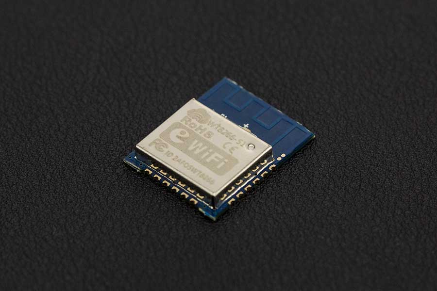
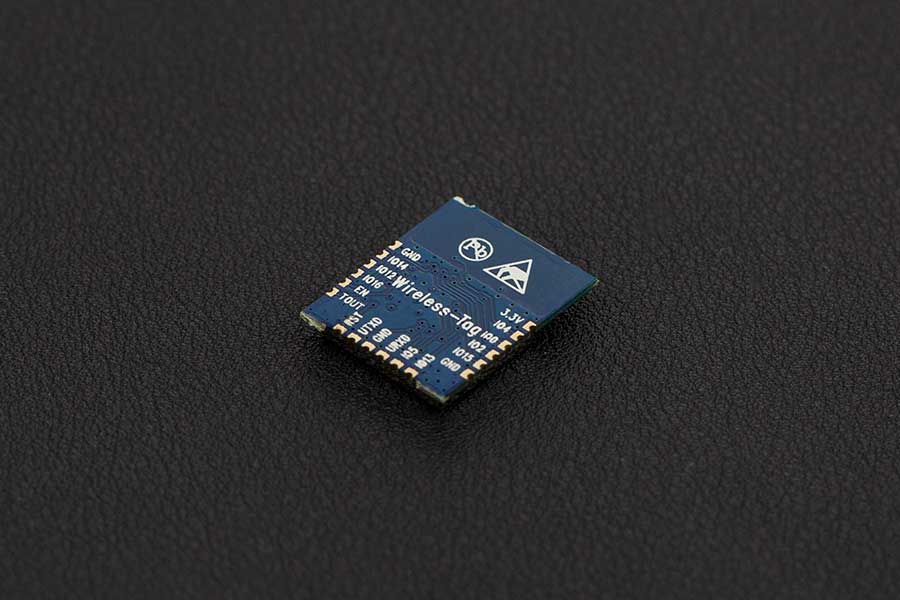
WT8266-S1 Wi-Fi module is a low consumption, high performance embedded Wi-Fi network control module designed by Wireless-Tag. It can meet the IoT application requirements in smart power grids, building automation, security and protection, smart home, remote health care etc.
The module’s core processor arduino ESP8266 integrates an enhanced version of Tensilica’s L106 Diamond series 32-bit processor with smaller package size and 16 bit compact mode, main frequency support 80 MHz and 160 MHz, support RTOS, integrated Wi-Fi MAC / BB / RF / PA / LNA, on-board PCB antenna. The ESP8266 WiFi Module is a self contained SOC with integrated TCP/IP protocol stack that can give any microcontroller access to your WiFi network.
The module supports standard IEEE802.11 b / g / n protocol, a complete TCP / IP protocol stack. Users can use the module to add networking capabilities for existing equipment , also can build a separate network.
Specifications
Operating Voltage: 3.3V
Operating Temperature:-40 – 85°C
CPU Tensilica L106: RAM 50KB(Available)Flash 32MB
System: 802.11 b/g/n
IntegratedTensilica L106 ultra-low power 32-bitmicro MCU, with 16 bit compact mode,main frequency
support 80 MHz and 160 MHz, support RTOS
WIFI 2.4 GHz, supportWPA/WPA2
Ultra-Small 18.6mm*15.0mm
Integrated 10 bit high precision ADC
Integrated TCP/IP Stack
IntegratedTR switch, balun, LNA, Power amplifier and matching network
Integrated PLL、Regulator and power source management components, +20 dBm output power in 802.11b mode
Supports antenna diversity
Deep sleep current < 10uA, Power down leakage current < 5uA
It can use an application processor SDIO 2.0、SPI、 UART
Polymerization of STBC、 1×1 MIMO、 2×1 MIMO A-MPDU 、A-MSDU and 0.4 s guard interval
Wake up within 2ms, connect and transfer data packets
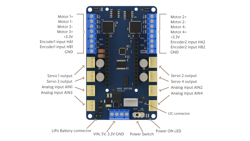
Want to connect several motors and sensors to your mechatronic project? The Arduino MKR Motor Carrier is the perfect companion for Arduino MKR boards as it will allow you to rapidly prototyping and build your projects.
The MKR Motor Carrier is an MKR add-on board designed to control servo, DC, and stepper motors. The Carrier can also be used to connect other actuators and sensors via a series of 3-pin male headers.
The summary of features is shown below:
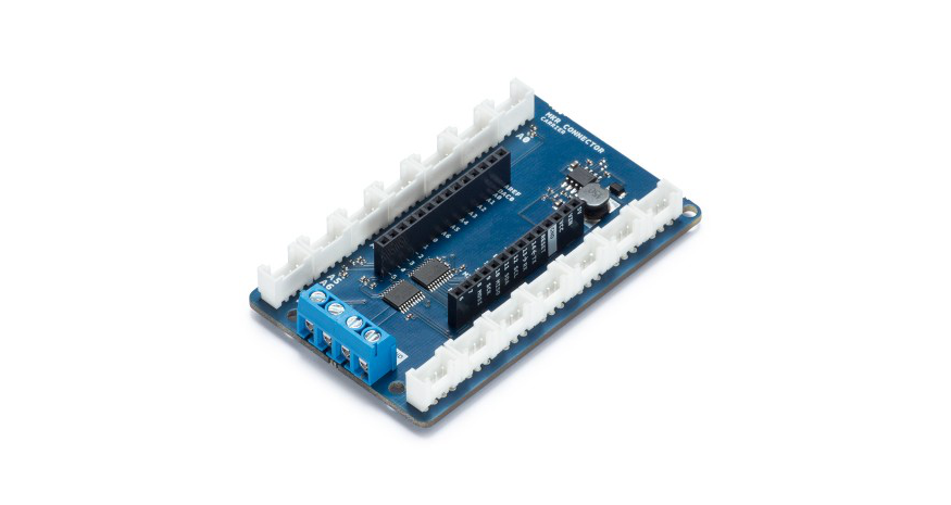
Compatible with all the boards in the MKR family
Four servo motor outputs
Four DC motor outputs (two high performance + two standard performance)
Sensing of current feedback for the high-performance motors
Two inputs for encoder sensors
Four inputs for analog sensors (3-pin compatible)
Possibility to read the status of the batteries
ON-OFF switch with Power ON LED
LiPo battery connector (2S or 3S compatible) and power terminal block for alternative power source
LEDs to visually indicate the direction of the rotation of the DC motors
On-board processor for automated control of some of the outputs
I2C connector as a 4-pin male header
The Arduino MKR Motor carrier is open-source hardware! You can build your own board using the files found on Arduino website.
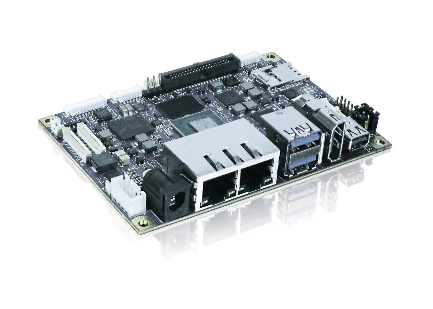
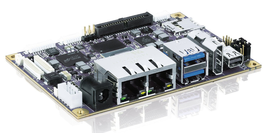
Kontron’spITX-iMX8M motherboard features NXP’s dual or quad core CPUs based on the Arm Cortex-A53 architecture with up to 1.5 GHz. The Cortex M4 coprocessor and full 4K UltraHD resolution make the board the perfect foundation for sophisticated applications. It offers enhanced connectivity through two Gigabit Ethernet interfaces as well as superior graphics performance. Thanks to its small form factor and M.2 half-size connector, offering PCIe, USB 3.0 and a Micro SIM interface, Kontron’s pITX-iMX8M is a cost-optimized ARM SBC solution, specifically for embedded applications in the manufacturing industry, and a cross-market IoT gateway for small server solutions.
The pITX-iMX8M enables processor configurations on 8M QuadLite or 8M Dual in either industry or consumer versions. It has 32 KB L1 instruction cache and L1 data cache per core. The Cortex M4 coprocessor supports 16 KB L1 instruction cache and L1 data cache per core with 256 KB Tightly Coupled Memory (TCM). The SBC pITX-iMX8M features 4 GB LPDDR4 3200 MTps memory down storage and 64 GB eMMC Memory v5.1 Nand Flash. The soldered RAM and flash memory make the pITX8M perfectly suited even for extremely rugged applications. There are extensive display connection options like a LVDS dual channel, a mini display port and a HDMI port. Further interfaces are two USB 3.0 ports at the back, two USB 2.0 ports via the internal header, 8 GPIOs and one S/PDIF internal header, audio line-in, line-out and microphone input. Kontron offers both a Yocto Linux BSP and an Android BSP (Board Support Package) for getting the pITX iM8M started fast.
The pITX-iMX8M supports Kontron’s security solution APPROTECT powered by Wibu-Systems. Based on an integrated Wibu-Systems security chip (CodeMeter) combined with a specifically developed software framework, it provides IP and copy/reverse engineering protection. Kontron APPROTECT Licensing also enables new business models such as “pay per use”, demo versions for limited time periods, or activation/deactivation functions via a predetermined set of variables.
Features:
Video quality with full 4K UltraHD resolution and HDR (Dolby Vision, HDR10, and HLG)
TPM2.0 and built in Hardware Security Device
M.2 Half Size Slot, uSD/uSIM Card Combo
4GB LPDDR4 Memmory down
mini DP + HDMI as Front Connector
Linux & Android BSP will be available
As for all embedded products, Kontron offers long-term availability of all components for the new pITX-iMX8M. The board is coming soon.
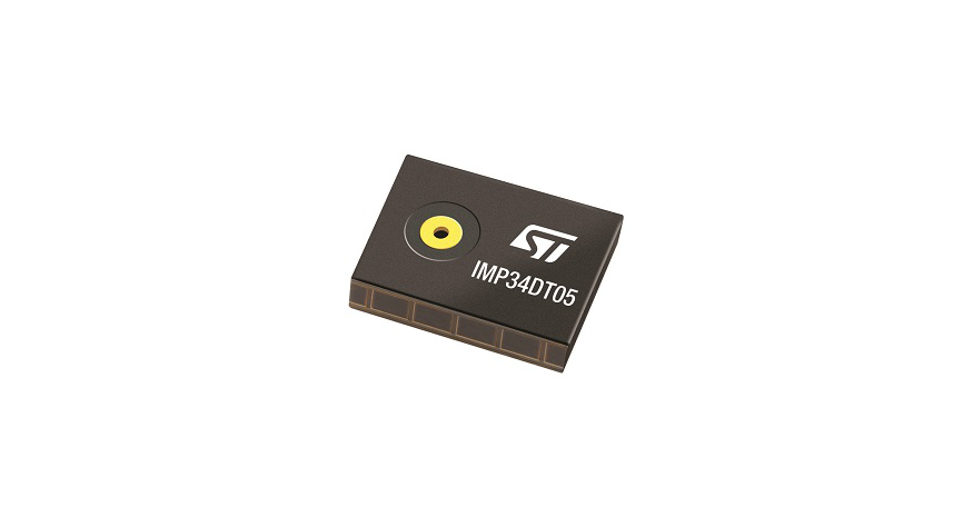
The IMP34DT05 is an ultra-compact, low-power, omnidirectional, digital MEMS microphone built with a capacitive sensing element and an IC interface.The sensing element, capable of detecting acoustic waves, is manufactured using a specialized silicon micromachining process dedicated to producing audio sensors.
The IC interface is manufactured using a CMOS process that allows designing a dedicated circuit able to provide a digital signal externally in PDM format.
The IMP34DT05 is a low-distortion digital microphone with a 64 dB signal-to-noise ratio and –26 dBFS ±3 dB sensitivity.
The IMP34DT05 is available in a top-port, SMD-compliant, EMI-shielded package and is guaranteed to operate over an extended temperature range from -40 °C to +85 °C.
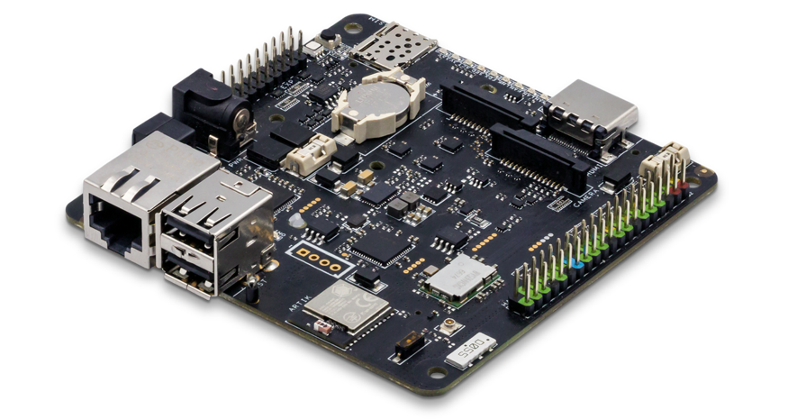
Balena, formally known as Resin.io has released an open source version of its IoT fleet management platform for Linux devices called openBalena. It is aimed at Intel NUC, Jetson TX2, Raspberry Pi, and a new RPi CM3 carrier called the balenaFin. Resin.io aimed to create a “git push for devices” and develop lightweight Docker containers for Linux devices to create easy security updates and IoT device management. Ever since, it has expanded beyond that to provide an in-depth, scalable platform for IoT fleet management. The company announced a name-change to Balena in conjunction with the release of an open source openBalena version of its software.
The change of name is due to trademark issues, to cannabis references, and to people mishearing it as ‘raisin
explained the founder and CEO Alexandros Marinos in a blog announcement.
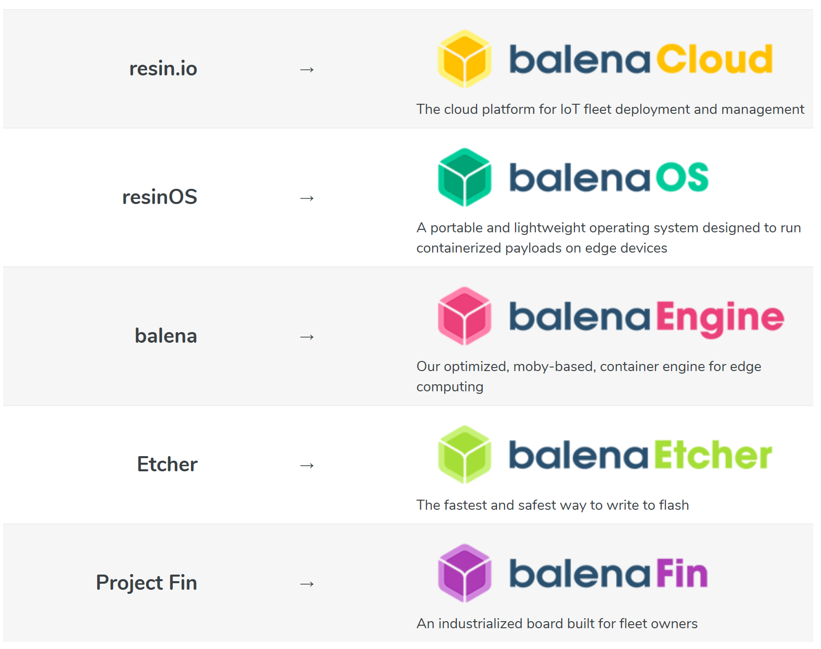
The new branding is based on the company’s balena container engine, now called balenaEngine, which derives its name from the engine’s underlying Moby Project container technology. The openBalena is an open source version of the Resin.io server/cloud platform for managing fleets of Linux-based IoT devices, now referred to as balenaCloud. The open source ResinOS distro is now referred to as balenaOS. Resin.io’s Etcher software for fast image writes to flash drives is now called balenaEtcher and the Project Fin carrier board for the Raspberry Pi Compute Module, which is now available starting at $129, is now called balenaFin.
The balenaOS is an open source spinoff of the container-based device software that works with balenaCloud, the new openbalena, on the other hand, is an open version of the balenaCloud server software. Users can now choose between letting balena manage their fleet of devices or building their own openBalena based server platform that manages fleets of devices running balenaOS. openBalena is a limited feature version of the commercial product. However, the components shared by both commercial and open versions are closely similar.
According to “Marinos”, this will allow them to release updates for the project as they update their cloud product, while also allowing open source contributions to flow back into the cloud product. The new deployment workflows and tools to enable this coordination will be announced soon.
openBalena has balenaCloud core features such as the powerful API, the built-in device VPN, as well as our spectacular provisioning workflow,
according to “Marinos”. It can also similarly scale to a large number of devices.
However, openBalena is single-user, instead of supporting multiple users. It’s controlled only through the already open sourced balena CLI tool rather than balenaCloud’s web-based dashboard, and it is void of “updates with binary container deltas.” Regarding the device aspect, openBalena incorporates the Yocto Project and Docker-based balenaOS. The client software has been updated to let devices more easily “join and leave a server”. This enables you set up your own openBalena server instead of being directed to balenaCloud. openBalena’s CLI allows you provision and configure devices, push updates, check status, and view logs.
Balena product family
Its backend features can securely store device information, enabling remote management via a built-in VPN service, and share container images to devices. On the server aspect, openBalena requires the following releases (or higher): Docker 18.05.0, Docker Compose 1.11, OpenSSL 1.0.0, and Python 2.7 or 3.4. The beta version of openBalena supports Raspberry Pi boards, Intel NUC boards, Nvidia Jetson TX2 module, and the new balenaFin. It seems it will eventually support the full list of devices supported by balenaCloud, like Samsung’s Artik boards, Variscite’s DART-6UL, Aaeon’s UP board, the Banana Pi M1+, BeagleBone, and BeagleBone Green/Green Wireless, SolidRun’s HummingBoard i2, the Odroid-C1/C1+ and Odroid-XU4, the Orange Pi Plus2, Technologic’s TS-4900, and Siemens’ IOT2000 gateway.
Artificial Intelligence has been the talks of most markets and development in the last few years. It is widely believed that the products and solutions of tomorrow will have one form of artificial intelligence built into them. Companies and Organisation are spending millions of dollars in R&D in the areas of AI in health, AI in transportation, AI in Finance and several others. What about the everyday makers? For us that don’t yet have access to the millions of dollars, how can we start innovating with AI especially AI in the Edge? Development platform like the Lichee Dan is making this possible.
Lichee Dan combines two beautiful worlds together: Open source and Artificial Intelligence into one single platform. Lichee Dan which is also officially named the Sipeed M1 series is an excellent open source AI development kit made by the team behind the LicheePi boards. They aim to promote AI-related development and education.
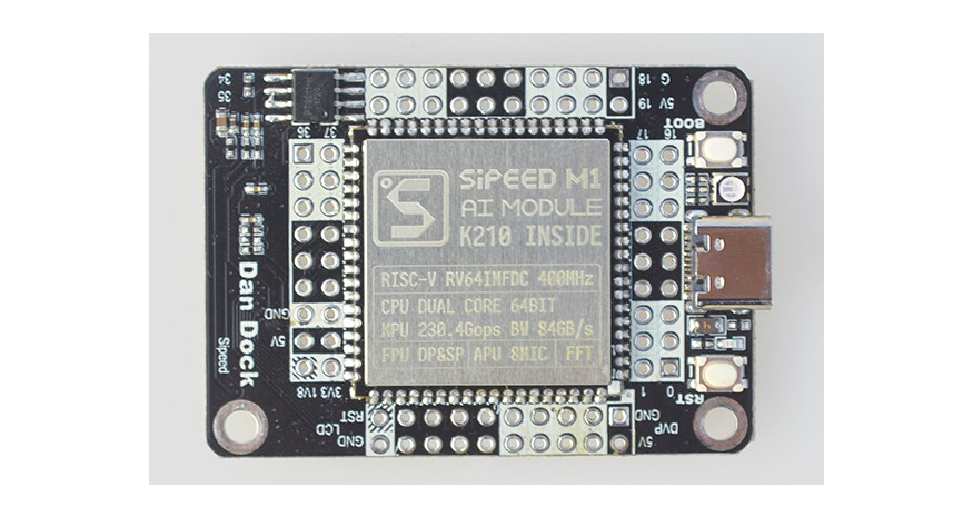
Sipeed M1 Module
Unlike the conventional C or C++ seen in most hardware boards, the Sipeed M1 integrates Micropython to make development pretty smooth and straightforward. At the heart of the Sipeed M1 platform is the AI chip K210 by Kendryte, a dual-core RISC-V with an FPU. It serves as the core unit and dual-core processing with independent FPU, 64-bit CPU and 8M in-built SRAM. With a 400Mhz adjustable nominal frequency it supports multiplication, division and square root operation.
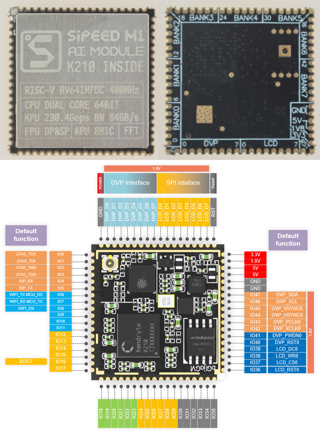
Below are the Sipeed M1 module specs:
SoC – Kendryte K210 dual core 64-bit RISC-V processor @ 400 MHz with KPU CNN hardware accelerator, APU audio hardware accelerator, 6 MB general purpose SRAM, 2MB AI SRAM memory, and AXI ROM to load user program from SPI flash
Package – 72-pin (25.4 x 25.4mm)
The Lichee Dan/ Sipeed M1 has the following features:
Neural Network Processor (KPU)
Audio processor (APU)
Fast Fourier Transform Accelerator (FFT Accelerator)
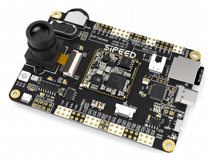
The 72pin board might be pretty difficult to use on its own, but thanks to the Sipeed MAIX development board called the Dan Dock, you can have access to all the functionality and some extras as well. In the AI processing, AI Chip (K210) can perform operations such as convolution, batch normalization, activation, and pooling. At the same time, the pre-processing of voice direction scanning and voice data output can also be performed. It offers [email protected], 400MHz, and when you overclock to 800MHz, it offers 0.5TOPS. This means you can do object recognition with a rate of 60fps@VGA resolution.
Sipeed M1 Development Board
The module is pretty powerful, and the video below shows an illustration of the device used for real-time face detection. One of the best thing about the module is not only the low cost and the small size but also the power consumption.
The main features of the development board include:
Storage – micro SD slot
Display I/F – An FPC24P socket for 8-bit MCU LCD
Camera I/F- An FPC24P socket for DVP camera
Audio – Power amplifier IC for use with speakers, built-in microphone
USB – USB Type-C interface
Connectivity – Optional WiFi
I/Os
On-board high-speed DAC
Access to all 72-pin full pin lead-out, freely mappable
The development board Dan Dock is currently being crowdfunded on IndieGoGo with different price offers ranging from $5 to about $15 for each unit. The Sipeed MI module is also available for purchase on Taobao (in Chinese) and yoycart for about $12.45. More information about the product is available on the campaign page and the module documentation.
Voltage is one of the fundamental values when dealing with electronics. It determines the amount and direction of current flow and represents the potential (electric charge) difference between two points, thus it is somewhat impossible to build or troubleshoot electronics circuits without being faced with the need to measure the voltage at one point or the other. The instrumentation device used for measuring the voltage is called a Voltmeter and for today’s tutorial, I will be demonstrating how you can build your own DIY version using an Arduino.
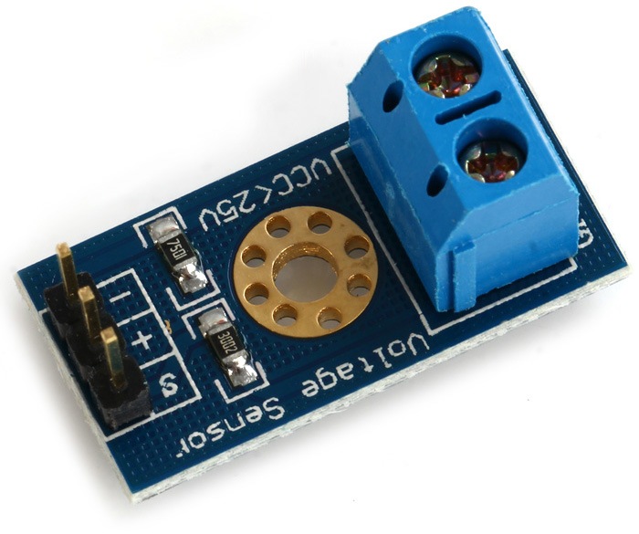
B25 Voltage Sensor module
Since voltage could either be direct (DC) or alternating (AC), one can either measure the AC or the DC voltage. For today’s tutorial, to keep things simple, we will focus on the measurement of voltage in a DC-based setup using the B25 voltage sensor module.
The B25 voltage sensor is a cheap, 25v maximum input, analog sensor which uses the voltage divider principle to give a value on output, corresponding to the input voltage. The sensor uses a linear conversion system such as that the value at the output is directly proportional to the input, thus, when working with the Arduino, it is important to ensure that a voltage greater than 25V is not applied at the module’s input as this will drive the voltage at the output beyond 5v which may lead to your Arduino board being damaged. While the sensor is probably cheap enough, you could build your own version using two resistors, set up as a voltage divider.
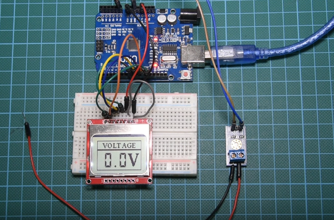
Arduino Voltmeter with LCD display
While several AC measuring principles exist, we can use a DC voltmeter to measure AC voltage but this should only be done after rectification and regulation of the input to a value tolerable by the DC side of the system. Correlation and mapping can then be done to indicate the value of AC voltage represented by the DC voltage (e.g 5VDC could represent 220VAC).
A major application of this project could be to keep track of the battery life of your project.
Required Components
The following components are required to build this project;
As usual, the exact one used for this tutorial can be bought via the link attached to them.
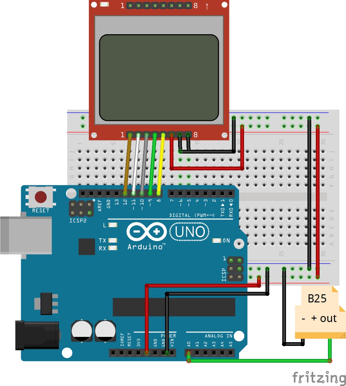
Schematics
The schematics for this project is quite easy. Connect the components as shown below.
Schematics
As mentioned earlier, the B25 voltage sensor is an analog device as such, its output is connected to the analog pin of the Arduino. To make the schematics easier to follow there is a breakdown of how the devices are connected, pin to pin.
We have done quite a number of tutorials which involves the use of the Nokia 5110 LCD. You may want to check one of them (especially this one) to better understand its connection and use.
With the connections done, we are now ready to write the code.
Code
The code for this project is quite simple. All we need to do is to read the voltage of the voltage sensor, convert it to the corrresponding voltage and display the value on the Nokia 5110 LCD Display. To display the information in a user-friendly manner, we will create a user interface for the LCD display which is attached together with the code in the zip file under the download section. We covered how to develop a user interface in one of the previous tutorials. To easily write the code to interface with the Nokia 5110 LCD display, we used the LCD5110_Graph library which can be downloaded from the link attached.
To do a run-through of the code; we will start by including the header files of the libraries that will be used, after which we create an object of the LCD library, specifying the pins of the Arduino to which the LCD is connected.
//written by Nick Koumaris
//info@educ8s.tv
#include <LCD5110_Graph.h> // THE LIBRARY I AM USING IS THIS:  http://www.rinkydinkelectronics.com/library.php?id=47

LCD5110 lcd(8,9,10,12,11);
Next, we specify the variable name to hold the font style, the UI, and the splash screen graphics after which we declare the analog pin of the microcontroller to which, the signal pin of the voltage sensor is connected.
extern unsigned char BigNumbers[];
extern uint8_t ui[];
extern uint8_t startScreen[];

float voltage = 0.0;
int sensorPin = A0;
We then declare some of the other variables that will be used.
Next is the void setup function. Here, we initialize the serial port and LCD after which, we issue the command to display the splash screen and set the font style to be used to display text on the LCD.
Next is the void loop function. The task under this section is simple; call the read voltage function to obtain the voltage value and display the value on the serial monitor and the LCD. The value is converted to a string for easy display on the LCD and a delay of 1000ms is applied after it has been displayed, just so it stays long enough on the screen to be seen before the Arduino code loops.
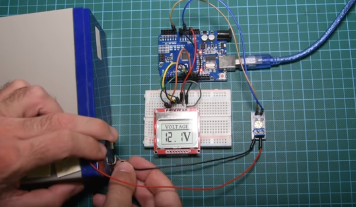
Upload the code to your Arduino and test with any battery or DC source you have. Ensure you don’t exceed the maximum input voltage of 25V so you don’t damage the Arduino. The LCD display should display the voltage level as shown in the picture below.
Demo
That’s it for this tutorial guys. Kindly drop any question or comments under the comments section. Will try to reply to as many as possible.
Till next time!
The video version of this tutorial can be found on youtube.