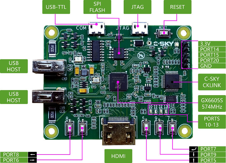
C-SKY Linux development board key features and specifications:
SoC – Nationalchip GX6605S C-SKY ISA V1 CK610M 32-bit processor @ 574 MHz with 64MB DDR2 RAM, built-in DVB-S2/S demodulator
Storage – 4MB SPI flash for bootloader and media player program
Video Output – HDMI output up to 1080p; framebuffer resolution (for UI): 1280×720
Video Playback – H.264 up to 1080p
USB – 2x USB2.0 host ports
Expansion – 5-pin header with 3x GPIOs, 3.3V, GND
Debugging
JTAG via XX32F103C8T6 USB-JTAG chip (micro USB port)
UART console via CH340g USB-UART chip (micro USB port)
Misc – 5 user buttons, reset button, 4x LEDs
Power Supply – 5V/1A via micro USB port (JTAG or UART)
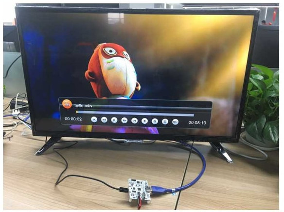
C-SKY board playing a 1080p h.264 video
There’s no network connectivity nor large storage on the board – everything runs from the 4MB SPI flash, but you can add Ethernet, WiFi, and/or storage via the USB ports.
Documentation – mostly in Chinese – is available on Github.io, and support provided via Github issues tracker. Their Linux 4.16 based firmware is build with buildroot + uClibc-NG, and you can run it in qemu if you don’t have the board.
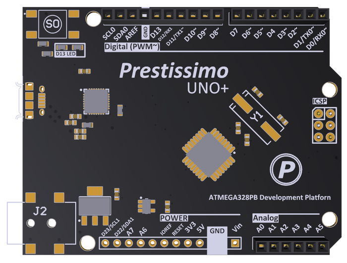
All the simplicity of the Arduino Uno plus extra I2C UART SPI ADC IO and PWM channels. A development board for the new ATmega328PB MCU.
The Prestissimo Uno+ is a platform for rapid electronics development and prototyping that brings us the simplicity, ease of use and reliability of the Arduino Uno but with extended functionality.
Despite numerous other options, the Arduino Uno has remained the most popular electronics prototyping platform for makers, engineers and hobbyists alike. At the heart of its success is the simplicity, ease of use and reliability of the AVR microcontroller. Unfortunately the Arduino Uno has an extremely limited feature set. Many times makers and developers are forced to compromise their design or to move to more complex platforms increasing time-to-market and making DIY projects less doable.
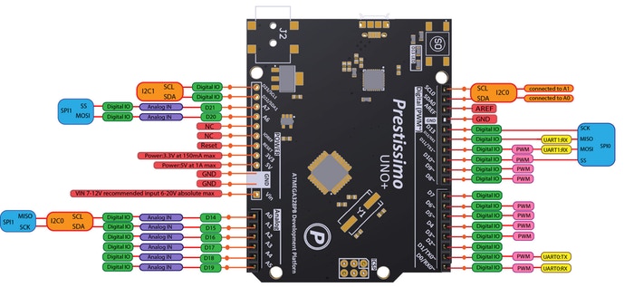
The Prestissimo Uno+ uses the new ATmega328PB microcontroller – an updated version of the Arduino Uno’s ATmega328P microcontroller. The “PB” version of the MCU builds on pre-existing functionality to include more SPI, UART and I2C ports (two of each instead of one), 9 PWM channels instead of 6, 8 ADC channels instead of 6, and 24 IO instead of 20 among other improvements. As the micro-controllers are so similar, full Arduino Uno compatibility is maintained meaning you get increased functionality while preserving the Arduino Uno experience.
Prestissimo Uno+: Arduino with more I2C UART SPI ADC IO PWM – [Link]
Gyrfalcon DevKit Simplifies Edge AI, Providing a complete suite of hardware and software tools for AI Model Creation.
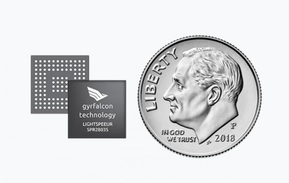
Gyrfalcon Technology Inc. (GTI), the world’s leading developer of low-cost, low-power, high-performance Artificial Intelligence (AI) processors from Edge to Cloud, today announced its DevKit, a set of development resources which makes it possible for smaller companies to achieve AI acceleration on existing devices such as smartphones, computers or industrial equipment. The cost-effective kit includes self-guiding online resources and two PLAI™ (“People Learning AI”) accessories that can run applications created to deliver Edge AI in devices using GTI’s first-generation chip, the Lightspeeur® 2801S.
Our DevKit is GTI’s response to companies and developers creating offerings for Edge AI. From large, household-name electronics manufacturers to small companies looking to use the right technology to create AI models independently, everybody can “Plai’ with AI,” said Marc Naddell, VP of Marketing & Sales, GTI. “With today’s launch, we are now able to offer a more diverse and flexible ecosystem of AI solutions.
The PLAI accessories are designed to be simple enough to use by non-experts:
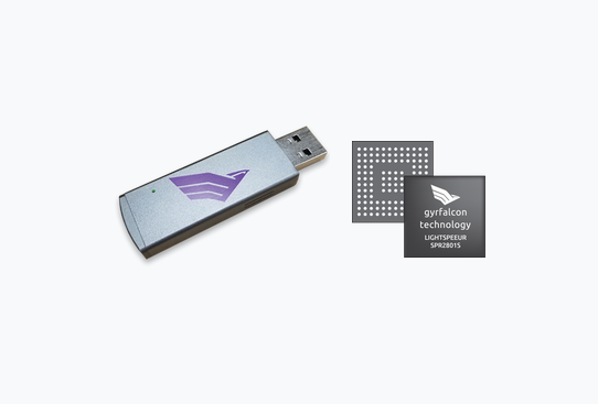
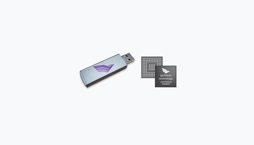
The PLAI™Plug is a USB3.0 dongle that plugs into laptops and other devices running a Windows, Linux or Android operating system. The PLAI™ Plug provides the AI accelerator to support applications developed by third parties that would run on a compatible laptop. Some examples include improving image resolution, transferring the style of a photo into that of a famous painter’s style or classifying images.
The PLAI™ Wifi is a small, wireless accessory that provides 14GB of secure storage, pairs with Android or iOS smartphones, and supports image classification, low-light image enhancements and other AI capabilities to demonstrate the power of GTI’s accelerator chips running locally on existing smartphones. The companion demo app (AI Buddy) includes several AI experiences such as the “Night Vision Filter,” which enhances dark photos with brightness and color.
Developers can write applications for the two PLAI™ accessories, which, when embedded with an AI model, can enrich existing devices with Edge AI-based experiences. This means users don’t need to upgrade their laptops or phones to a new, high-end model to experience Edge AI.
Along with the PLAI accessories, the DevKit provides access to online resources to facilitate AI model creation. These include documentation, a forum and the PLAI™ Builder, a lightweight AI training and modeling platform. Together, these assets provide users with everything needed to create commercial-grade AI models for GTI chipsets.
The DevKit is available directly from GTI. The PLAI™ Wifi device will also be made available as a standalone to be sold by a partner retailer (sign up to get notified).
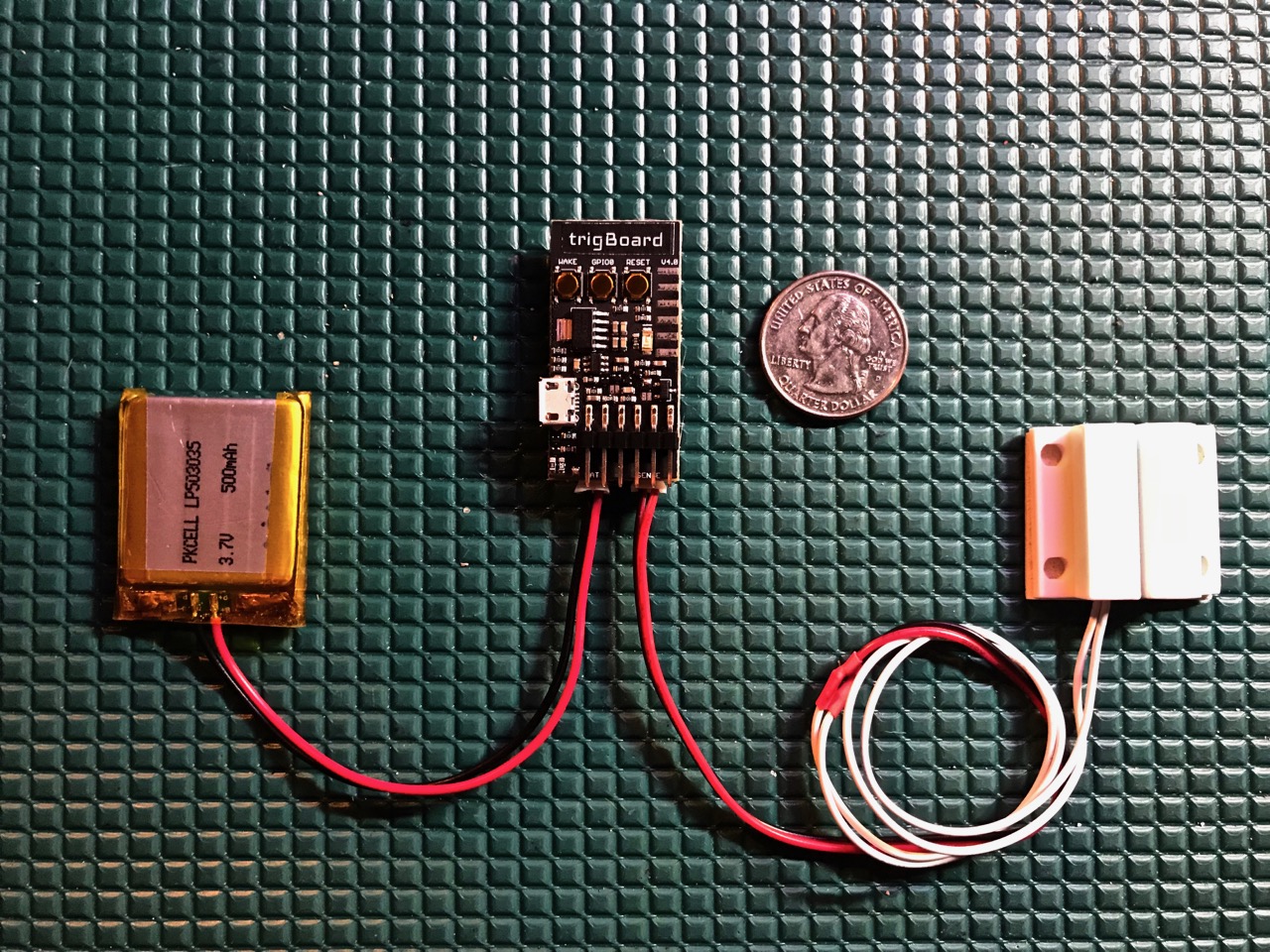
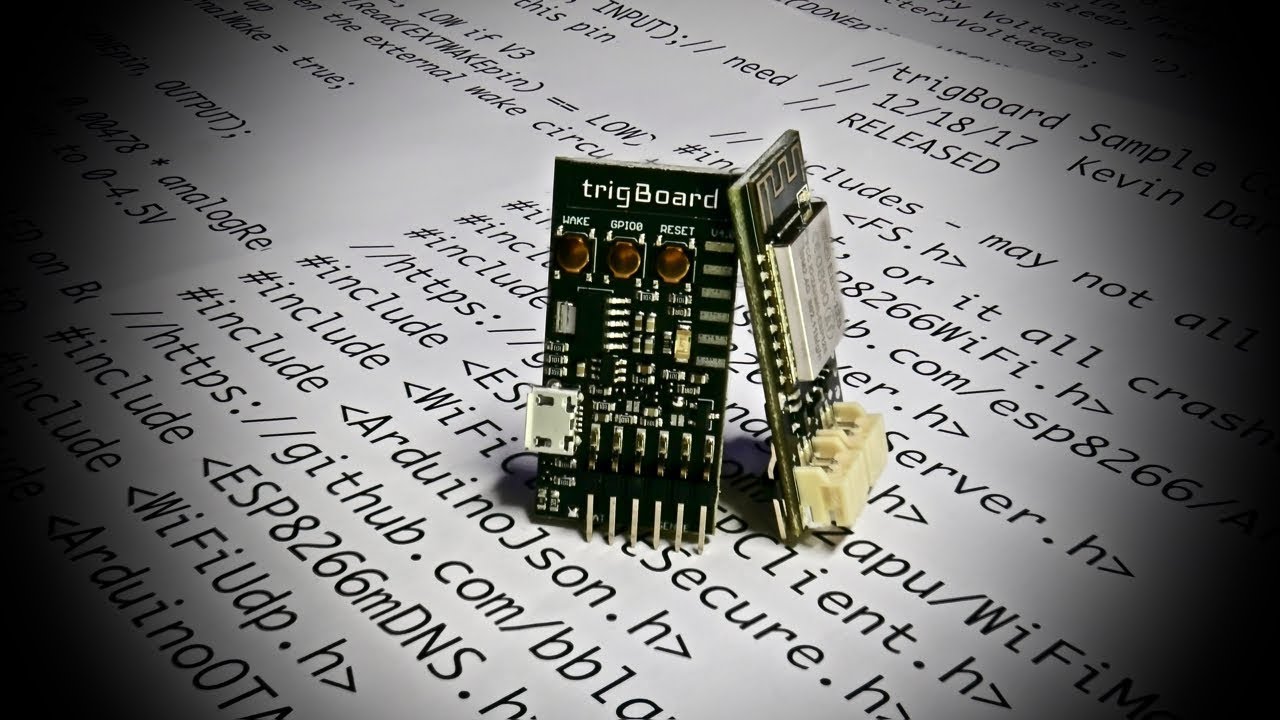
The trigBoard is an IoT project that does one thing – it pushes you a notification triggered by a digital input. Well, it’s much more than that, but this is the inspiration. I wanted to design a WiFi board that essentially sleeps most of its life, but when that door switch, flood sensor, motion sensor, etc.. gets triggered, I just want a notification immediately on my phone. And that’s about it… a perfect IoT device in the background doing its job.
Features
Simple IoT development board that was designed to trigger “Push Notifications” on a smart phone/tablet based on a trigger event.
Unique low-power front-end to enable sub 1uA sleep current – uses a pulse to trigger wake-up, so even if door/window/etc is opened, the same ultra low currents can be maintained. Compare to standard pull-up/down resistor based digital input designs with significantly higher leakage current.
The board will wake itself up once an hour to check the battery voltage – if running low, a push notification is sent to warn the user. This timer can be used to check other things as well – temperature changes, accelerometers, or other environmental sensors.
Based on ESP8266 WiFi Module (ESP-12S) – all source code is available for download and developed in the popular Arduino IDE.
Battery Input can be any Lithium Polymer 3.7V – standard micro JST connector jack is used (please double check polarity),any of these would work nicely.
Sensor input to trigger the “Wake Up” is a simple passive switch. Typically a standard magnetic door/window switch is used and the board can be configured to wake on the “opening” (Normally Closed) or “closure” (Normally Open) of the contact. Solder jumpers set this – Normally Closed is Default, so standard door/window switches wake the board up when opened.
Battery Charging On-Board via MicroUSB – set for 4.2V at 500mA. 5V input pads broken out for energy harvesting experimentation.
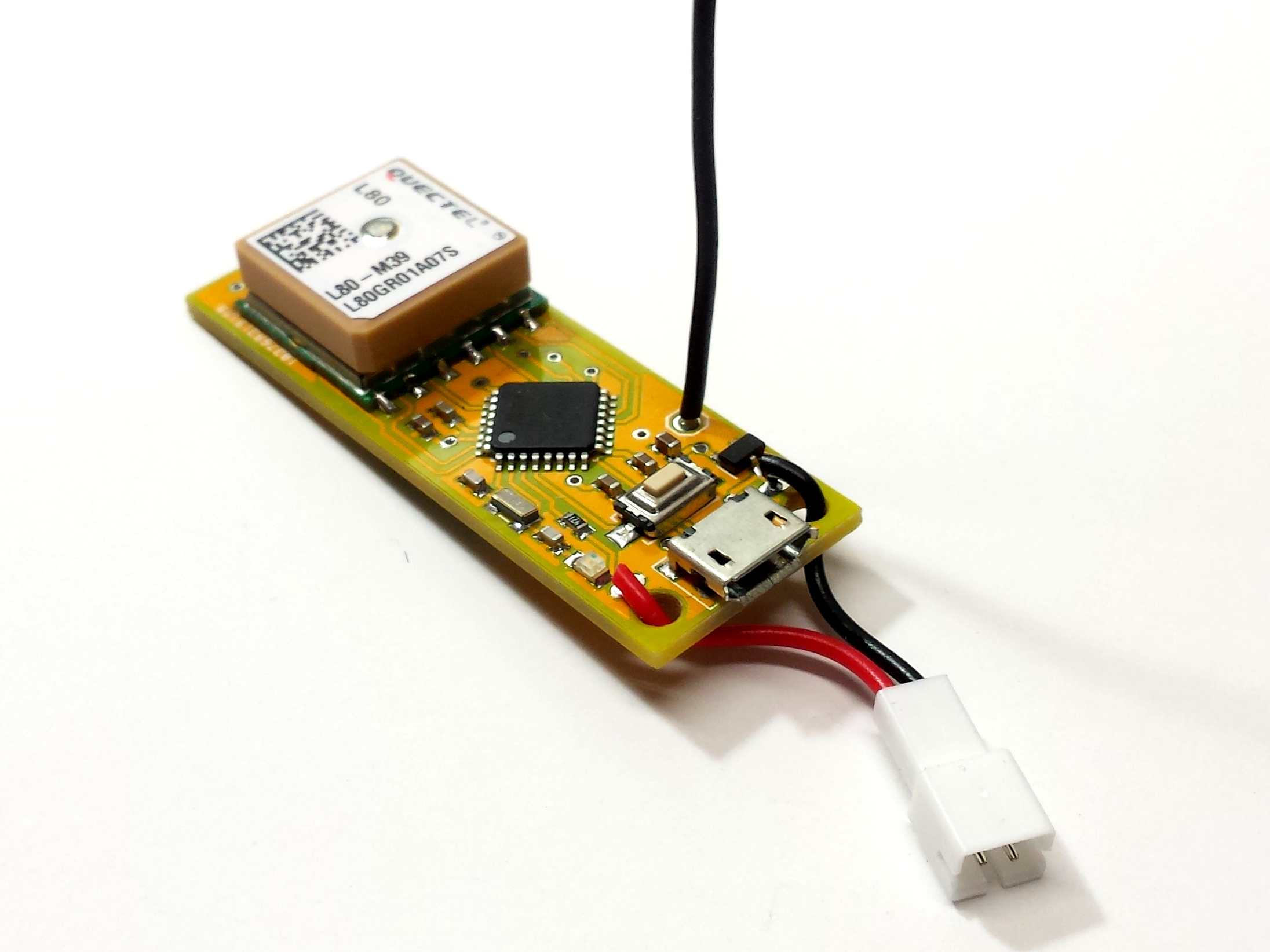
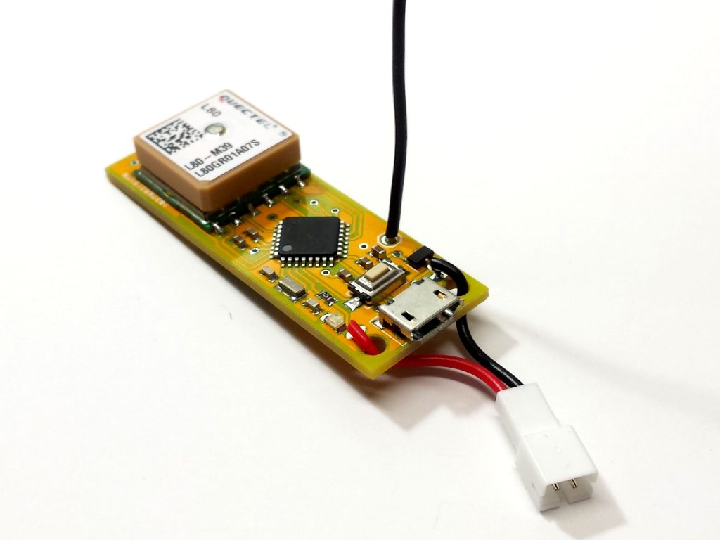
Michael Krumpus designed and built a SAMD21 development board with LoRa radio module and GPS receiver, that is available on GitHub:
I’ve been doing some LoRa projects lately in order to learn as much as I can about this exciting new radio technology (see this LoRa mesh networking project and this LoRa weather station). ATmega328-based Moteino modules work great for a lot of projects, but I wanted a LoRa node with more processing power, more memory, and an onboard GPS receiver. The ATmega328 is just too constrained with memory — I’ve outgrown it. I really wanted a LoRa board with an ARM Cortex microcontroller like the SAMD21. This is the microcontroller used on the Arduino Zero. So, my ideal board is a SAMD21 with LoRa radio module and GPS receiver, all programmable with the Arduino IDE.
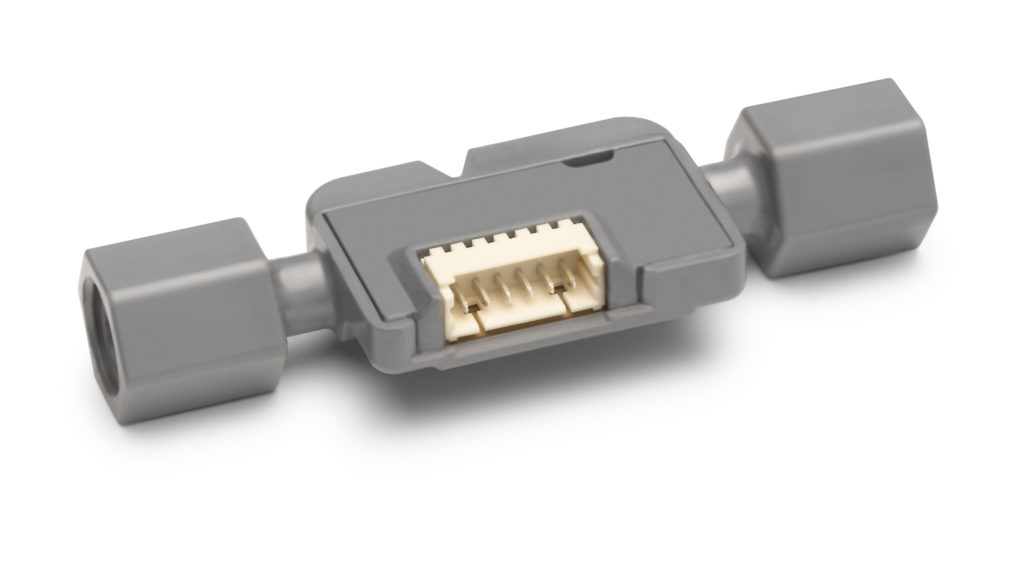
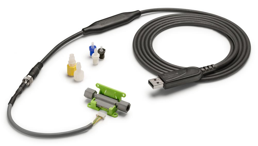
Sensirion presents its latest liquid flow sensor, the SLF3S-1300F, at the Electronica and COMPAMED 2018 trade fairs. By combining Sensirion’s excellent 20-year track record in low and lowest flow rate sensing with a radically optimized mechanical design, the SLF3S-1300F takes the well-established functionality to the next level in price-performance ratio. The sensor provides maximum safety, stability and long-term reliability for a wide range of applications, including the fields of diagnostics, analytical instruments and life sciences.
The SLF3S-1300F liquid flow sensor is based on Sensirion’s proven CMOSens® Technology and optimizes costs by simplifying the design without sacrificing the easy fluidic, electrical and mechanical connections. The straight and unobstructed flow channel has no moving parts; inert wetted materials provide outstanding chemical resistance and excellent media compatibility. In measuring flow rates up to 40 ml/min bi-directionally, the sensor allows monitoring the entire system operation and detecting common failure modes.
The SLF3S-1300F enables applications in the fields of diagnostics, analytical instruments and life sciences to reach unparalleled fluid control, system reliability and thus new heights in performance and end-user satisfaction. Its compact form factor and cost-effective design permit system designs with one or more sensors that were previously unfeasible.
Samples of the SLF3S-1300F liquid flow sensor are available now for testing. Please contact Sensirion for further information at info@sensirion.com.
Features:
Highly integrated: Linearized, temperature-compensated and fully calibrated digital output signal (I2C) from a single chip
Full scale flow rate for water-based liquids: 40 ml /min
Turn down ratio 200:1 or better
High speed measurement: Response time below 20 ms
Bidirectional measurement and real time failure detection
Easy fluidic and electrical integration via ¼″-28 flat bottom ports and a standard connector
Straight, unobstructed flow channel without moving parts
Media isolated sensing principle: no direct sensor contact with the fluid
Compact and light-weight form factor
Chemically resistant wetted materials
Commercial release of the sensor is planned for 2019.
Discover the SLF3S-1300F liquid flow sensors at this year’s Electronica (Hall B3, Booth 417) and COMPAMED (Hall 8a, Booth H19.6) trade fairs. For more information, please visit: www.sensirion.com/slf3x
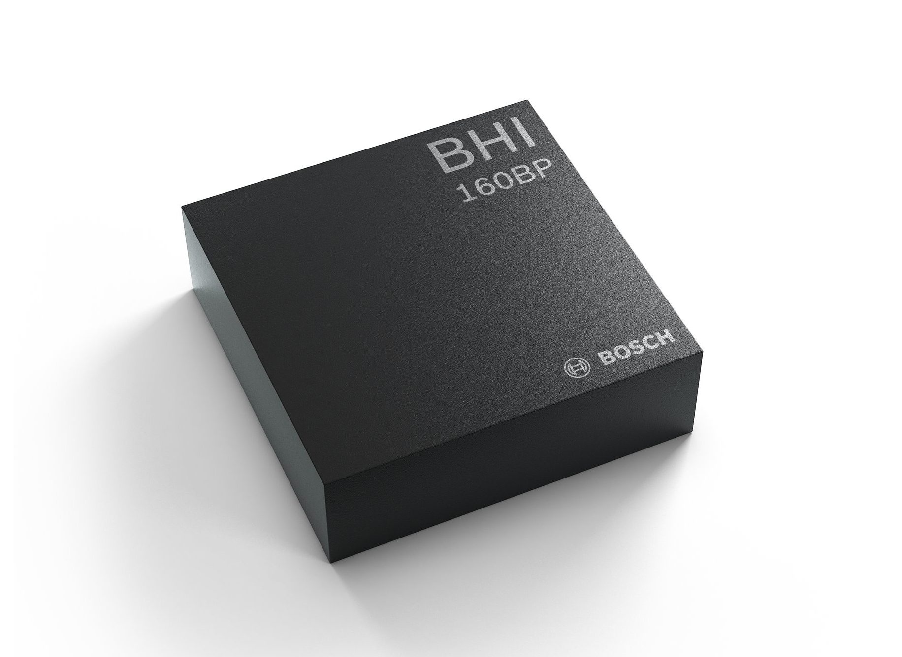
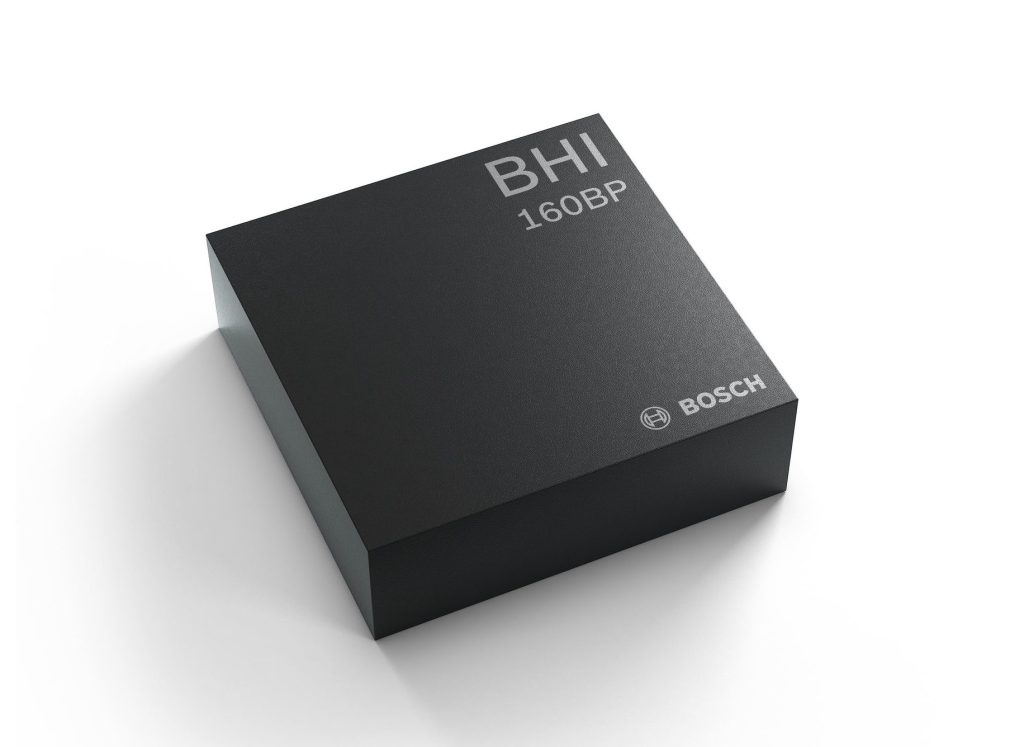
Reutlingen/Munich, Germany – At electronica Munich, Bosch Sensortec announces the BHI160BP, the industry’s first Position Tracking Smart Sensor that utilizes integrated inertial sensors to improve GPS location tracking.
Always-on position tracking
When used with a GPS or GNSS module, the BHI160BP enables users to take full advantage of pedestrian position tracking with up to 80% saving in system power consumption compared with a typical GNSS-only solution, without compromising on accuracy. Users benefit from a greatly extended battery life and longer charging intervals for wearable applications such as smartwatches and fitness trackers and other mobile devices such as smartphones or hearables. This new position tracking approach is set to enable a new class of compact devices with even smaller batteries.
The BHI160BP tracks a person’s position by intelligently applying an inertial sensor based algorithm for Pedestrian Dead Reckoning (PDR). To maintain accuracy, it calculates the user’s relative location based on data collected from the inertial sensors and then re-calibrates itself every few minutes to obtain the absolute position provided by the GNSS/GPS module. This means that the GNSS/GPS module can be kept in sleep mode for most of the time, which drastically reduces a device’s power consumption and extends its operating time.
Pedestrian position tracking is a crucial application for mobile applications; unfortunately, GPS modules can rapidly drain a device’s battery capacity – especially when the battery is as small as in wearable devices,” says Dr. Stefan Finkbeiner, CEO of Bosch Sensortec. “Our new Position Tracking Smart Sensor solves this problem and enables users to navigate reliably while extending the operation of GPS tracking in their devices from several hours up to several days.
Straightforward integration
The position tracking capability provided by the BHI160BP also means that a device can maintain solid accuracy even when the GNSS signal is blocked or weak, e.g. near tall buildings or indoors. This ensures accurate pedestrian navigation at all times, even in shielded indoor areas such as subways.
The BHI160BP is a new member of Bosch Sensortec’s BHI160 family and adds application-specific functionality for position tracking. It provides a ready-to-use solution that can be quickly and easily integrated into a system design without requiring an update to a new GNSS module, thereby significantly cutting time to market.
While the current configuration is optimized for use with GNSS receivers (such as GPS), the BHI160BP can also support most of the common global localization technologies. As well as improving localization, the BHI160BP can also serve to handle gesture recognition and 3D orientation, with 3D calculations performed by the sensor itself rather than by an application processor.
Wide range of features and functionalities
The new BHI160BP draws only 1.3 mA in active operation mode and is the industry’s lowest-power solution that integrates the Fuser Core (MCU) and a 6-axis Inertial Measurement Unit (IMU). Additionally, the Position Tracking Smart Sensor offers a variety of customized virtual sensors, such as a calibrated accelerometer, orientation and wake up gesture, within a single device. Furthermore, the BHI160BP can be extended by connecting additional physical sensors, such as a magnetometer, over a secondary interface.
The new BHI160BP comes in a compact 3 x 3 x 0.95 mm³ LGA-package and is pin-to-pin compatible with the BHI160.
Features:
Ultra-low power position tracking reduces system power consumption by up to 80%
Seamless and more reliable localization than GPS-only solutions
Wide range of features like 3D orientation and gesture recognition
Bosch booth at electronica Munich: hall C3, booth 522
Availability
The BHI160BP will be available via distribution in December 2018.
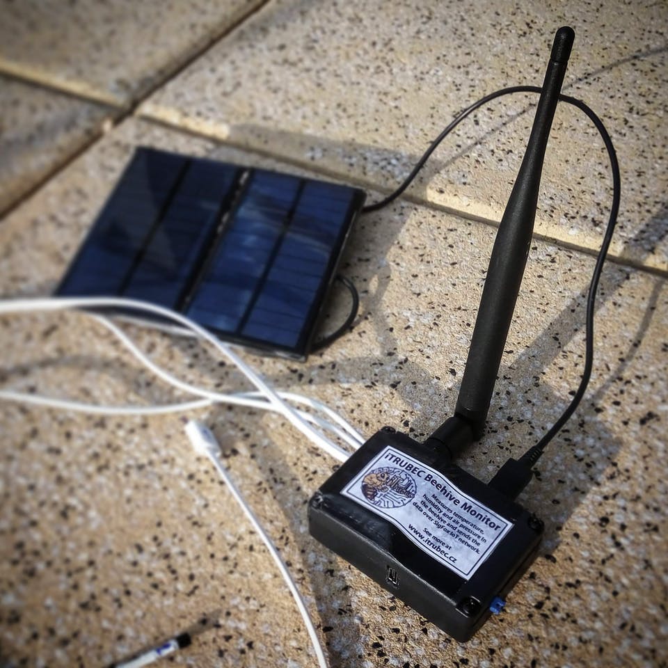
Small temperature/humidity/atmospheric pressure monitor using Sigfox to transfer the data. Powered by solar energy to monitor beehives.
We wanted to monitor beehive remotely and online. You would say it is easy to use mobile data for such purpose. But there are some cons: The coverage is not good enough, not all the people do have mobile data activated, the pricing is quite high for our purpose and last but not least such solution consumes a lot of electricity causing the battery dry in a day or two.
Solar Powered Beehive Monitor Using Sigfox network – [Link]
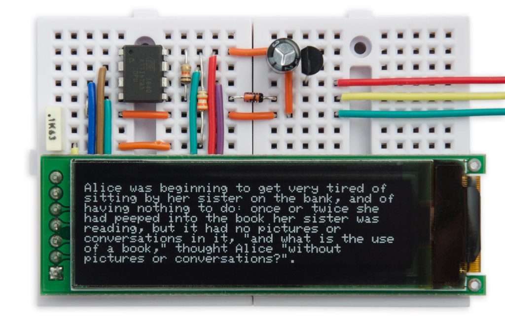
This is a Tiny Serial Terminal based on ATtiny85 and 256×64 OLED SH1122 display able to show 42 characters per line. David Johnson-Davies writes:
This article describes a text display based on a 256×64 OLED display that provides 8 lines of 42 characters per line. Its width makes it ideal for displaying text or program listings, unlike the more common 128×64 displays. The display is driven by a standard 9600 baud serial interface, making it ideal for debugging serial devices, or as a self-contained character display for a project. Both the display and serial input are handled by an 8-pin ATtiny85, and it’s based on my earlier project Tiny Terminal.
Fingerprint sensing is one of those technologies in science fiction movies that fascinated most of us as kids. Today, they are everywhere and asides from existing in everyday devices with huge electronics complexity, like mobile phones, they are also available in tiny modules to give makers and electronics hobbyists, the ability to include them in their own projects. For today’s tutorial, we will look at the use of a fingerprint sensor with Arduino.
Fingerprint sensors are based on diverse kind of technology, from capacitive fingerprint sensors used in recent mobile phones, to optical fingerprint sensors commonly used in access control applications. For today’s project, we will use an optical fingerprint sensor.
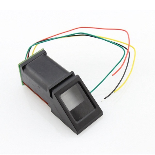
Optical Fingerprint sensor
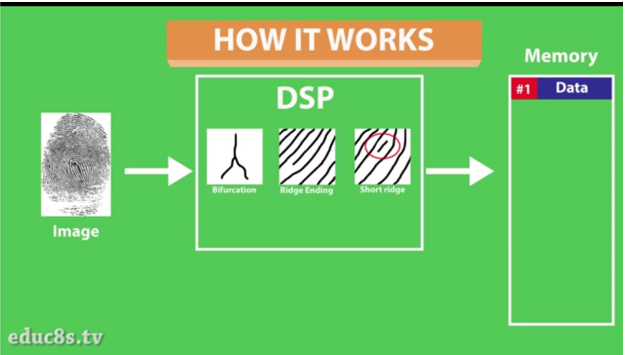
The Optical fingerprint sensor is a highly compact device. It comes embedded with an advanced DSP (Digital Signal Processing) chip, which is used to process the image of fingers captured and determine if a match exists or not.
When the sensor captures a new image, it is rendered and the distinguishing features are extracted. The memory of the sensor is searched for a fingerprint with matching characteristics and the result of that session is sent to the microcontroller via serial communication. All of this is done in less than a second. The module can store up to 1000 fingerprints in its memory and its false acceptance rate is less than 0.001% which makes it pretty secure!
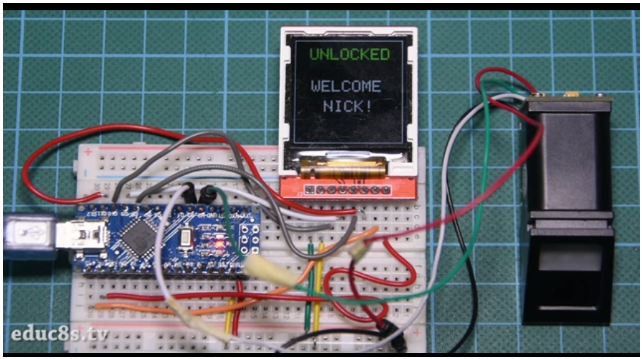
To demonstrate the use of this module with the Arduino, we will build an access notification system. We will use a TFT display alongside the fingerprint sensor and an Arduino nano, to build a simple device that displays “UNLOCKED” when there is a fingerprint match and displays “LOCKED ” when there is no match.
Required Components
The following components are required to build this project;
These components, can be purchased via the links attached to them. The Power bank is optional but provides a very easy way to power the project when it is not connected to your computer.
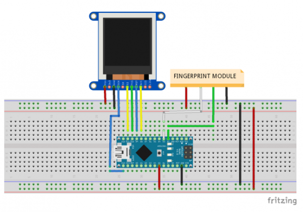
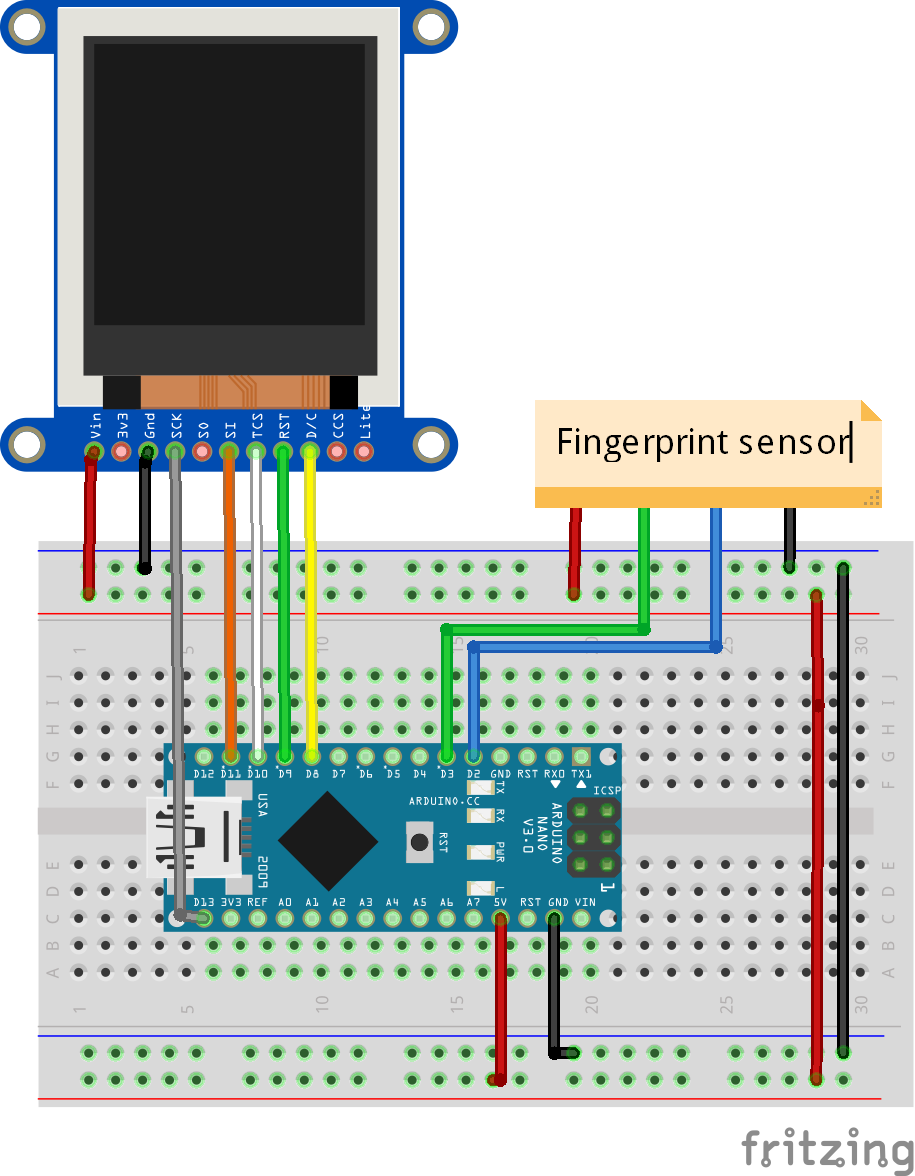
Schematics
Connect the components as shown in the schematics below. The particular optical fingerprint sensor used for this tutorial is not available on Fritzing, so a makeshift version was used.
Schematics
As mentioned earlier, the optical fingerprint sensor communicates with microcontrollers over UART (Serial communication) and as such only requires 4 wires to connect it to the Arduino. The second significant element of the schematic is the 1.44″ color TFT LCD display and a detailed tutorial about its use is found on the link.
To make the connections easier to follow, especially since a makeshift representation was used for the fingerprint sensor, the pin connections are mapped below.
The pins of the fingerprint sensors are sometimes not labeled but differentiated with the color codes of the wires. It is important you check the description of the sensor to know what color of wire was used for each pin. If you have any further problems with connection, feel free to reach out via the comment section.
Code
The code for this project relies heavily on the fingerprint sensor library from Adafruit. The library reduces the amount of code that is needed to interact with the sensor by compressing them into functions. The library can be downloaded here. To easily interact with the TFT display also, we will use the popular Adafruit GFX library and the ILI9163C library from Somutoy.
To do a brief explanation of the code, we start by including the libraries we will us.
//written by Nick Koumaris
//info@educ8s.tv
#include <SPI.h>
#include <Adafruit_GFX.h>
#include <TFT_ILI9163C.h>
#include <Adafruit_Fingerprint.h>
#include <SoftwareSerial.h>
#include <avr/pgmspace.h>
Then we define the colors that will be used in the display.
#define BLUE    0x001F
#define RED     0xF800
#define GREEN   0x07E0
#define CYAN    0x07FF
#define MAGENTA 0xF81F
#define YELLOW 0xFFE0
#define WHITE   0xFFFF
The next important line is the creation of a software serial instance to enable the Arduino to communicate with the fingerprint sensor. The hardware serial was not used because it is the same pins that is being used by the Arduino to communicate with the computer.
Next is the void loop function. In this function we check for a finger present every 50ms. If a finger is found, the module checks to see if the fingerprint is stored in its memory. If it is present, it generates the fingerprint ID and displays the name of the user. After a few seconds, the screen is locked again.
Enrolling a finger before uploading the code for this project is important and can be done by uploading the enroll example from the Adafruit fingerprint library to our Arduino board. We go to File-> Examples -> Adafruit Fingerprint Sensor Library -> Enroll. With this example program, we can store fingerprints in the FLASH memory of the module. We upload the sketch and open the Serial Monitor. The program asks us to enter the ID to enroll. Then we place the finger on the sensor twice as we are instructed and the fingerprint is stored! You can store as many as 1000 fingerprints this way.
The complete code for this project is shown below and also attached under the download section.
As mentioned above, you should use the enroll examples to enroll new fingerprints. Once this is done, Upload the code of this tutorial to your Arduino board. You should see the display come up after a while, waiting for you to place a finger on the fingerprint sensor. If an existing finger is placed, “UNLOCKED” will be displayed on the TFT display as shown below. If the finger has not been registered it will display “DENIED”.
Demo
That’s it for today’s tutorial. If you have any question in regards to this, do not hesitate to drop it under the comment section below.
Till next time!
The video version of this tutorial is available on youtube.