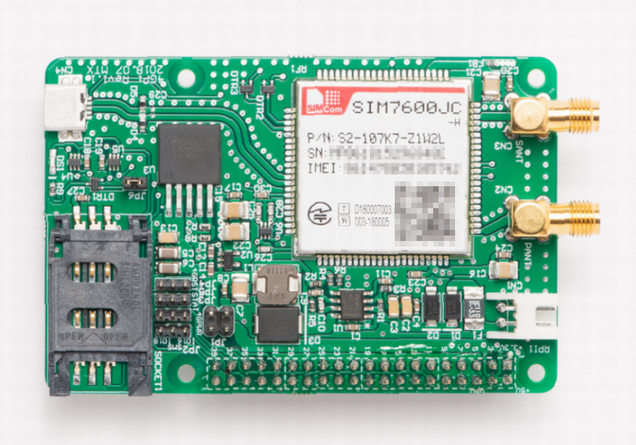
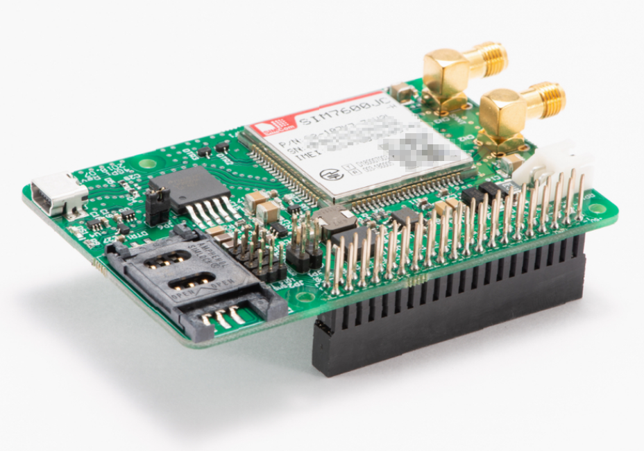
MechaTracks has announced a CAT4 4G LTE HAT board for the Raspberry Pi called 4GPi. The 4GPi is the first commercially produced add-on board which enables CAT4 LTE connectivity for the Raspberry Pi, enabling 150Mbps download and 50Mbps upload speed. The 4GPi sells for ¥25000 JPY yen or €195 (about $222) and is over twice the cost of existing LTE add-on boards such as the Cat.M1 and NB-IoT compliant Sixfab Raspberry Pi Cellular IoT Application Shield, which is restricted to 375Kbps up and down. There are many 3G Raspberry Pi add-ons like Linkwave’s Pilot and MechaTracks’ own 3GPi. The 4GPi is designed around a SIMCOM SIM7600JC-H LTE Cat4 module. This enables LTE bands 1, 3, 8, 18, 19, and 26, that are usually employed across Europe, South America, and Japan, Korea, Thailand, India, Australia, and New Zealand.
According to the chipset documents, this variant does not have fallback capabilities for UMTS / HSPA or GSM / GPRS / EDGE networks. A Raspbian image is available to make setup easy. The 4GPi is equipped with dual external antennas and appears to incorporate a micro-USB port. It supports any Raspberry Pi that has a 40-pin connector and includes passthrough pins and a jumper switch to enable other HATs to be used on the same Pi. For example, the board can work together with MechaTracks’ ADPi ADC board and RTC equipped SleePi power management board.
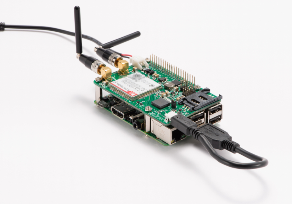
Sales of the 4GPi start on November 1, for ¥25000 JPY ($222 USD / €195 EUR). It is available from Amazon Japan (with international shipping possible), as well from RS Components and SwitchScience. While the price of 4GPi is a bit higher than that of the base Raspberry Pi board, the two combined, are still to a large extent more affordable than other LTE-connected development devices available in the market, making it a more suitable option for projects which require mobile network connectivity, particularly digital signage, security and asset tracking, and agricultural/environmental use cases, where constant Wi-Fi connection is unreliable and impractical.
4gpi with Raspberry Pi
Mobile network operators are preparing for the wide deployment of 5G, and existing IoT devices, that rely on legacy 3G networks will have to be replaced in order to maintain connectivity with the servers which push updates and receive updates from these devices. For example, In July, Verizon stopped activating devices which only 3G support, making new deployments of devices which rely on their legacy 3G CDMA network impossible. Verizon is planning to decommission their 3G CDMA infrastructure at the end of 2019. Other mobile carriers in the US and worldwide are expected to follow that.
Further information may be found on the MechaTracks 4GPi product page, which offers direct sales and links to RS Component and SwitchScience shopping pages.
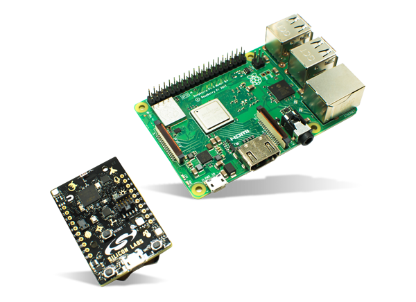
UrsaLeo Pi based on Raspberry Pi compute engine cuts costs and unleashes full capabilities of Thunderboard™2 sensor module.
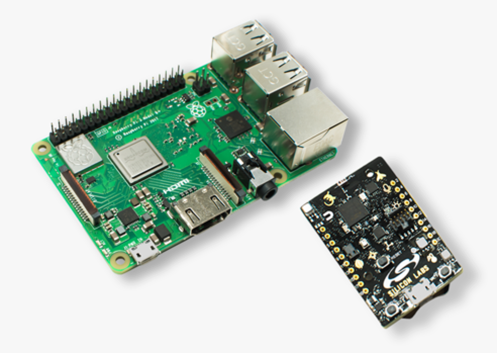
UrsaLeo Pikit, which combines a Raspberry Pi 3 and a 2.4GHz radio equipped Silicon Labs Thunderboard 2 sensor board that connects to Google Cloud, has been launched by RS Components. UrsaLeo’s kit, which was recently initiated by Mouser, was originally called “UrsaLeo UL-RPI1S2R2” and is designed to send sensor input to Google Cloud for storage and analytics. The kit is designed for Industry 4.0, automotive diagnostics, healthcare, and general data monitoring.
UrsaLeo Pi kit
The UrsaLeo Pi has the same Silicon Labs Thunderboard Sense 2 sensor board, which is present in the earlier UrsaLeo UrsaCloud UltraLite, also named the UrsaLeo UltraLite or UL-NXP1S2R2. While the UltraLite kit incorporates the Thunderboard 2 with NXP’s official development board for its Cortex-A7 based iMX6 UltraLite (UL) SoC, the UrsaLeo Pi makes use of a more powerful Raspberry Pi 3 SBC.
The UltraLite version has a better debugging functionality than the Pi, and also has reduced “restrictions on hardware re-use,” says RS Components. Nevertheless, the Pi version is faster and much cheaper. The Pi costs 154 Pounds ($197) without VAT at RS Components in comparison to 455 Pounds ($582) for the UltraLite. Mouser’s prices are $195 and $550, respectively. The Thunderboard Sensor 2 (or Thunderboard 2) board is equipped with temperature, humidity, UV, ambient light, barometric pressure, indoor air quality, and gas sensors.
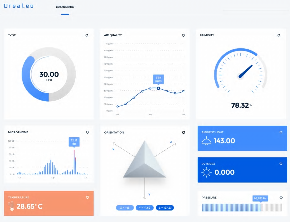
Ursaleo Dashboard
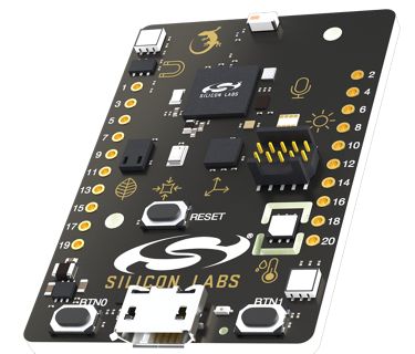
Available also, is a 6-axis inertial sensor, a digital microphone, and a Hall sensor. The board is fitted with Silicon Labs’ EFR32 Mighty Gecko multi-protocol radio, which enables 2.4GHz wireless technologies such as Bluetooth Low Energy (BLE), Thread, ZigBee, or proprietary short-range protocols. The kit is pre-installed with an OTA-updatable Linux stack based on Yocto Project code. It automatically connects to a pre-registered Google Cloud account. Up to 50MB of data per month can be uploaded to the cloud platform free of charge.
Silicon Labs Thunderboard 2 sensor board
A dashboard, which can be customized, allows users to view sensor data and launch IoT applications such as storage and analytics, according to RS Components. The dashboard, which has sharing capabilities with third parties, streamlines the addition of new sensors and support user-definable events to generate alerts. Sample applications and APIs are available to manage sensors, run diagnostics, and pass on information with enterprise or business intelligence applications. Bluetooth sensor and Ethernet connectivity code samples are included on the shopping page.
There are no technical details on how the two boards connect or whether any of the Pi’s GPIO remains accessible when connected to the Thunderboard 2. Mouser, however, state that the kit includes a Strontronics universal power supply for the Pi.
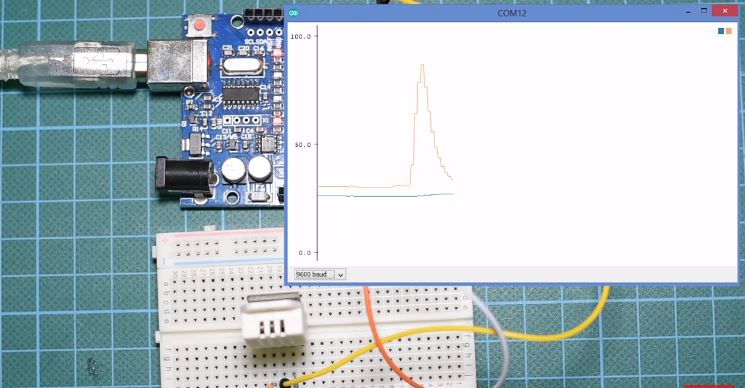
Visualizing data when working with the Arduino is something we all have had to do using third party/ self-developed software in the past. It was thus, it is really interesting when the Arduino team decided to change that recently. Today, we are going to take a look at their solution, called, the Serial Plotter, a new tool that comes with the latest version of the Arduino IDE.
The serial plotter provides a medium through which we can see a plot of the data being printed to the Arduino’s serial port in real time. Before the inclusion of this feature in the Arduino IDE, developers/makers usually have to write additional code using other tools and programming languages like Python or more popularly Processing to get a plot of the Arduino’s Data. This at times makes debugging difficult due to the extra work and time it requires especially in waveform based applications where viewing the data on the serial monitor will not be sufficient.
The serial plotter basically takes values coming from the preset serial port and plots them on a x-y axis graph. The Y-axis represents the values from the serial port and automatically adjusts itself as the value increases or decrease. The X-axis can be said to represent an instance of time. Each point on the x-axis represents the execution of a println statement within the Arduino code. In plainer terms, each time a println command is executed, a new point/data (value of Y corresponding to that particular println statement) is recorded on the graph. The limitation of the serial plotter in this version of Arduino IDE is the fact that it only supports a total of 500 data samples, after which the plotter may need to be restarted. This may make the plotter, unsuitable for certain applications, but I believe this will change with upcoming versions of the IDE.
The Serial Plotter
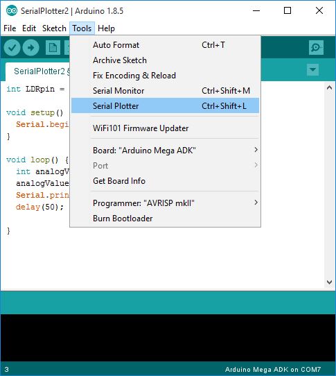
The serial plotter can be invoked after uploading code to the Arduino board, by clicking on tools -> serial plotter from the drop-down menu or by pressing CTRL + SHIFT + L which is the keyboard shortcut for the same.
Launch the Serial Plotter
To demonstrate the use of serial plotter in today’s tutorial, we will build two examples.
For the first example, we will use the Serial Plotter to plot the data from a photoresistor. This will give us the ability to examine how the data changes with the luminous intensity without trying to make sense of the numbers being printed over the serial monitor.
For the second example, we will be using a DHT22 temperature and humidity sensor. The goal of this example will be to show how to plot the data from multiple sensors using the Arduino serial plotter.
Required Components
The following components are required to build the two examples for this tutorial:
These components, as usual, can be purchased via the links attached to each of them.
Schematics
If you have been a follower of our tutorial series on this website, you should be very familiar with the schematics for this project. For simplicity, we will use one schematic for each example.
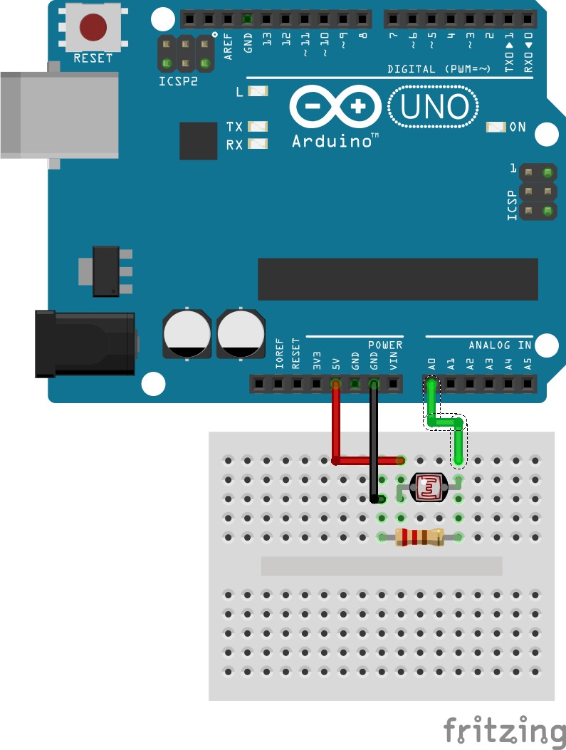
For the first example which involves plotting of photoresistor’s data, the circuit is essentially a voltage divider connected to an analog pin on the Arduino. The divider is made up of the photoresistor on one part and an ordinary resistor on the other part. Connect the components as shown in the schematics below.
Schematics for Example 1 – Photoresistor
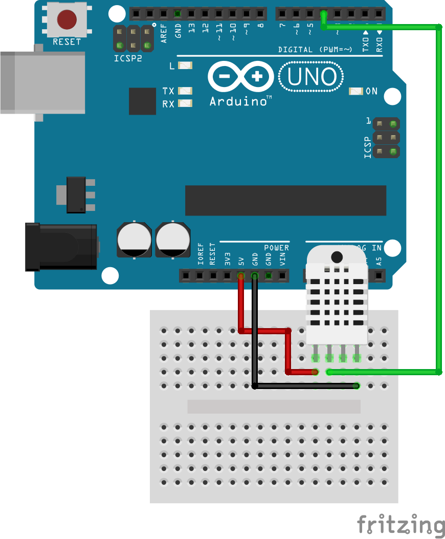
For the second example, the circuit comprises of the DHT22 temperature and humidity sensor connected to the Arduino as shown in the schematics below.
The pin connections between the Arduino and the DHT are further described below.
DHT22 – Arduino
VCC - 5V
GND - GND
Data - D4
Code
The code for the two examples that we will work with are quite simple. You would have, at one point or the other, seen them on this website as we have lots of weather station based tutorials. However, the important thing in both codes is the println() function. The Serial.println() Arduino function prints data to the serial port as human-readable ASCII text followed by a carriage return character (ASCII 13, or ‘\r’) and a newline character (ASCII 10, or ‘\n’). This command takes the same form as Serial.print() statement with the only difference being the newline character which is not associated with the serial.print(). As mentioned during the introduction, everytime the serial.println() command is issued, data is recorded on the serial plotter thus making it very important to this tutorial.
With that said, let’s take a look at the code for the examples starting with the first one.
Code for Plotting the Photoresistor’s Data
To do a brief explanation of how the code for this example works, we start by indicating the pin of the Arduino to which the output of the divider is connected.
//Written by Nick Koumaris
// info@educ8s.tv

int LDRpin = 0;
int analogValue =0;
Next, is the void setup() function, where we initialize the serial port, setting the communication baud rate to 9600.
void setup() {
  Serial.begin(9600);
}
Last but not least, we write the void loop() function. Under this function, we use the analogRead() function to obtain data from the voltage divider pin after which the data is sent to the serial port using the serial.println() command.
//Written by Nick Koumaris
// info@educ8s.tv
int LDRpin = 0;
int analogValue =0;
void setup() {
Serial.begin(9600);
}
void loop() {
  analogValue = analogRead(LDRpin);
  Serial.println(analogValue);
  delay(50);

}
Code to Plot Data from the DHT22 Sensor
The main reason for this example as mentioned earlier is to demonstrate how to plot multiple data representing multiple variables using the serial plotter.
For this example, we will be obtaining and plotting the ambient temperature and humidity from the DHT22 at the same time. To briefly explain the code, we start by including the DHT.h header to utilize the functions in the DHT library.
//Written by Nick Koumaris
// info@educ8s.tv

#include "DHT.h"
Next, we specify the pin of the Arduino to which the signal pin of the DHT sensor is connected and specify the type/model of the DHT being used.
#define DHTPIN 4
#define DHTTYPE DHT22
We also initialize (set to zero) the variables that will hold the temperature and humidity data from the sensor. After this, we create an instance of the DHT library specify the pin of the Arduino to which the signal pin is connected and the type of DHT we are using.
Next, we write the void setup() function. We start this function by initializing the serial port, setting its baud rate to 9600 after which we initialize the DHT sensor.
The void loop() function, as usual, is where most of the work is done. We start by using the dht.readTemperature() and dht.readHumidity functions to obtain the temperature and humidity value from the sensor. After which we proceed to print them out in a way that the serial plotter understands the difference between the variables. This is the done by printing an empty space between the variables (after the first value, before the second value). Without this empty space between the data, the plotter will see the next println statement as an update to the previous one.
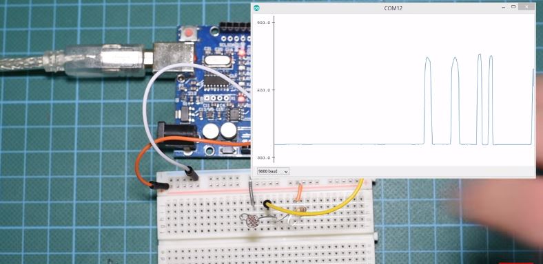
This project is quite simple and I expect no complications to arise, but in case things get funny, do ensure your connections are as described in the schematics. For each example, after double checking your connections, upload the corresponding code to the Arduino board and open the serial monitor. You should see the data being plotted after a while as shown in the images below.
Example 1: Photoresistor data Plotted by the Serial Plotter
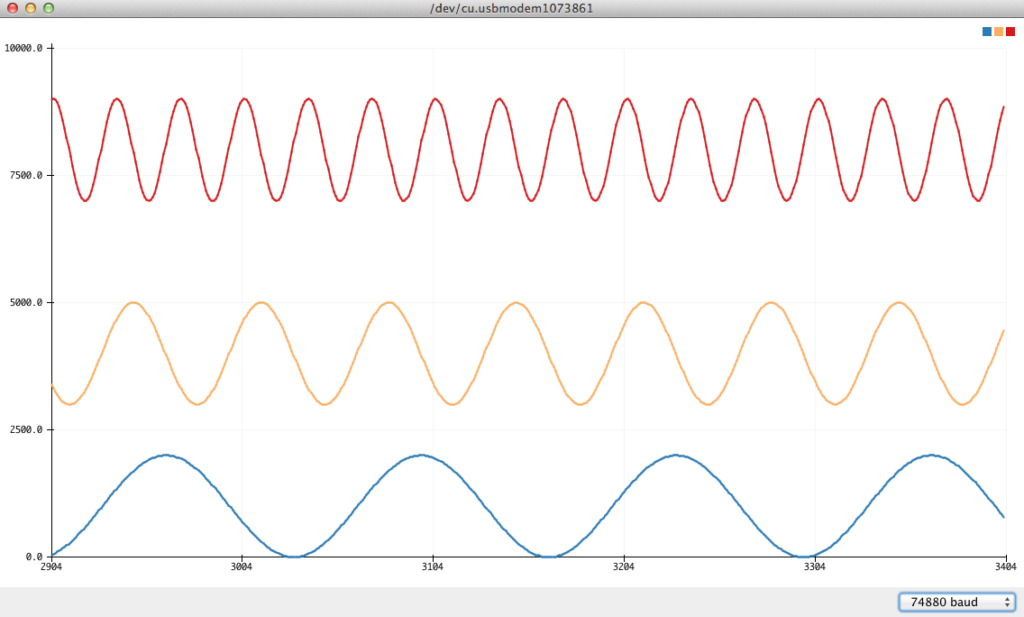
Example 2: Temperature and humidity data plotted at the same graph.
That’s it for this tutorial guys, thanks for reading. If you have any questions or discover new tricks with the recent versions of Arduino IDE that you will like to share, don’t forget to drop comments.
Till next time!
The video version of this tutorial is available on youtube.
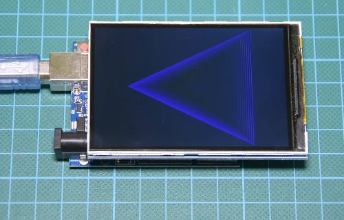
Displays are one of the best ways to provide feedback to users of a particular device or project and often the bigger the display, the better. For today’s tutorial, we will look on how to use the relatively big, low cost, ILI9481 based, 3.5″ Color TFT display with Arduino.
ILI9481 3.5″ LCD TFT Display
This 3.5″ color TFT display as mentioned above, is based on the ILI9481 TFT display driver. The module offers a resolution of 480×320 pixels and comes with an SD card slot through which an SD card loaded with graphics and UI can be attached to the display. The module is also pre-soldered with pins for easy mount (like a shield) on either of the Arduino Mega and Uno, which is nice since there are not many big TFT displays that work with the Arduino Uno.
To show how the display works and how to use it with Arduino based projects, we will run simple demos to display graphics and texts on the display.
Required Components
The following components are required to replicate this tutorial:
The module is compatible with either of the Arduino Uno or the Arduino Mega, so feel free to choose between them or test with both. As usual, these components can be bought via the links attached to them.
The power bank included in the component list is for those who want to test the projects when not connected to a PC.
Schematics
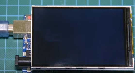
One of the good things about this module is the ease with which it can be connected to either of the Arduino Mega or Uno. For this tutorial, we will use the Arduino Uno, since the module comes as a shield with pins soldered to match the Uno’s pinout. All we need to do is snap it onto the top of the Arduino Uno as shown in the image below, thus no wiring required.
Plug the Display to the Arduino
This ease of using the module mentioned above is, however, one of the few downsides of the display. If we do not use the attached SD card slot, we will be left with 6 digital and one analog pin as the module use the majority of the Arduino pins. When we use the SD card part of the display, we will be left with just 2 digital and one analog pin which at times limits the kind of project in which we can use this display. This is one of the reasons while the compatibility of this display with the Arduino Mega is such a good news, as the “Mega” offers more digital and analog pins to work with, so when you need extra pins, and size is not an issue, use the Mega.
With the module connected, we can now move to the code.
Code
To easily write code to use this display, we will use the GFX and TFT LCD libraries from “Adafruit” which can be downloaded here. With the library installed we can easily navigate through the examples that come with it and upload them to our setup to see the display in action. By studying these examples, one could easily learn how to use this display. However, I have compiled some of the most important functions for the display of text and graphics into an Arduino sketch for the sake of this tutorial. The complete sketch is attached in a zip file under the download section of this tutorial.
As usual, we will do a quick run through of the code and we start by including the libraries which we will use for the project, in this case, the Adafruit GFX and TFT LCD libraries.
//Written by Nick Koumaris
//info@educ8s.tv
#include <Adafruit_GFX.h>
#include <Adafruit_TFTLCD.h>
Next, we declare the pins of the Arduino to which our LCD is connected, and create variables for fonts and colors using matching hex values.
#define LCD_CS A3
#define LCD_CD A2
#define LCD_WR A1
#define LCD_RD A0
#define LCD_RESET A4

#define BLACK   0x0000
#define BLUE    0x001F
#define RED     0xF800
#define GREEN   0x07E0
#define CYAN    0x07FF
#define MAGENTA 0xF81F
#define YELLOW  0xFFE0
#define WHITE   0xFFFF
Next, we create an object of the TFTLCD library with the pins of the Arduino to which the LCD is connected as arguments.
With this done, the Void Setup() function is next. We start the function by issuing a tft.reset() command to reset the LCD to default configurations. Next, we specify the type of the LCD we are using via the LCD.begin function and set the rotation of the TFT as desired. We proceed to fill the screen with different colors and display different kind of text using diverse color (via the tft.SetTextColor() function) and font size (via the tft.setTextSize() function).
Next is the void loop() function. Here we basically create a UI to display the youtube subscribe button, using some of the same functions we used under the void setup() function.
The Adafruit library helps reduce the amount of work one needs to do while developing the code for this display, leaving the quality of the user interface to the limitations of the creativity and imagination of the person writing the code.
The complete code for this example is shown below.
Copy the code above, and after installing the libraries, upload to your setup. You should see the display come up as shown in the image below.
Demo
That’s it for this tutorial guys, thanks for reading. If you made some cool projects based on this or you just want to ask questions about this tutorial, feel free to reach out via the comment section below.
Till next time!
The video version of this tutorial is available on youtube.
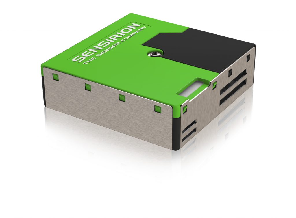
The SPS30 particulate matter sensor is now available worldwide through Sensirion’s distribution network.
The SPS30 particulate matter (PM) sensor is the next technological breakthrough in optical PM sensors. Its measurement principle is based on laser scattering and makes use of Sensirion’s innovative contamination-resistance technology. This technology, together with high-quality and long-lasting components, enables accurate measurements from its first operation and throughout its lifetime of more than eight years. In addition, Sensirion’s advanced algorithms provide superior accuracy for different PM types and higher-resolution particle size binning, opening up new possibilities for the detection of different sorts of environmental dust and other particles. With dimensions of only 41 x 41 x 12 mm3, it is the perfect solution for applications where size is of paramount importance, such as wall-mounted or compact air quality devices.
Traditional optical PM sensors suffer from contamination, which causes output degradation. Contamination results from continued dust and particle accumulation on the sensor’s optical components, namely the light source (usually a laser or LED) and the photodetector. Consequently, devices integrating these PM sensors stop working correctly after some time, which results in malfunctions, user complaints, maintenance, service and/or part replacement. Sensirion’s proprietary contamination-resistance technology and long-lasting components provide the SPS30 with unmatched robustness, unique long-term stability and high accuracy, together with a lifetime of more than eight years in continuous mode operating 24 hours/day.
Visit Sensirion at electronica 2018 (Booth 417, Hall B3) and learn more about the SPS30 particulate matter sensor, Sensirion’s latest breakthrough in environmental sensing technology.
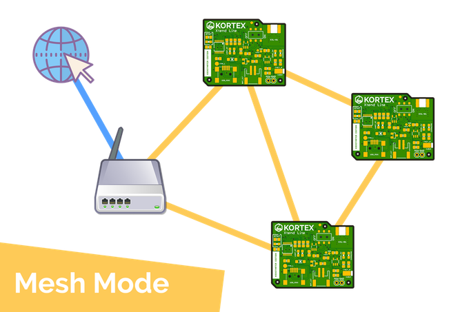
A Wi-Fi repeater is a device used to improve the coverage area of a WiFi network by amplifying existing WiFi signals and re-transmitting them. WiFi Repeaters undisputedly have quite some applications like for enhancing IoT applications connectivity, as a generic WiFi extender, ethical hacking, network security, packet sniffing, and much more. Most of the ones you see available don’t come cheap and don’t offer off the shell hacking (the fun part). That’s what Kortex Xtend Lite hopes to solve.
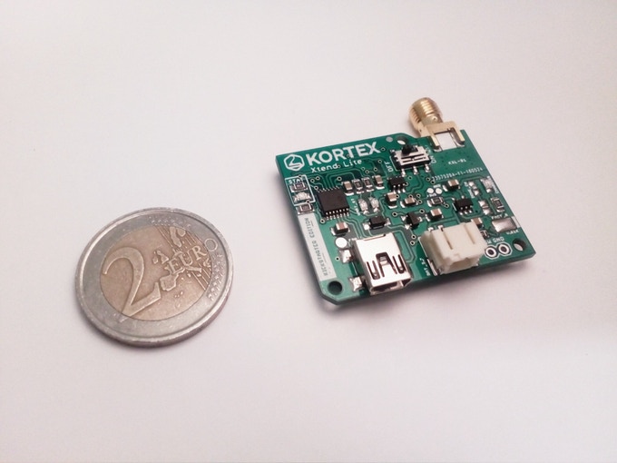
The Kortex Xtend Lite is a WiFi repeater created by the eighteen-year-old Amine Mansouri t0 serve as a multipurpose Wi-Fi Repeater while still being cheap and battery powered. Comes in a pocket-friendly device, you can always take it everywhere you go.
Kortex Xtend Lite
The board is based on the inexpensive WiFi microchip ESP8226-07S. The chip enables microchips to connect to WiFi networks using Hayes-style commands. The module is combined with a low power Tensilica Xtensa 32-bit L106 microprocessor. The repeater also comes with a 6dBi omnidirectional WiFi antenna which is great for working with mesh repeaters.
Kortex Xtend Lite comes with a built-in MCP73831 for battery charging and management allowing it to charge a Lithium-ion battery attached and can easily be charged from its mini USB port with any readily available 5V adaptor. It comes with an indicator RGB LED for indicating different operating modes.
Kortex Xtend Lite will easily find various applications in several domain spaces. At home – one can set up the Kortex Xtend Lite as a free open WiFi access point without necessarily giving out your WiFi password. It offers a NAT capability where it protects ones connected devices by its IP masquerading feature which protects the identity of the devices by implementing a network address translation procedure giving them a unique private IP address hidden behind a single public IP address (repeater IP address), so you can keep a bunch of devices hidden from hackers.
Some other interesting applications of the device are listed below:
Range extender for a WiFi network
Limiting maximum bitrate for all connected clients
Ethical hacking experiments
WiFi vulnerability tests
Battery powered wireless NAT repeater
Setting up an additional WiFi network with different SSID/password for guests
Setting up a secure and restricted network for IoT devices
Monitor probe for WiFi traffic analysis
Packet sniffing
Network experiments with routes, ACLs
Traffic shaping
Setting up a secure, wireless, battery-powered mesh network
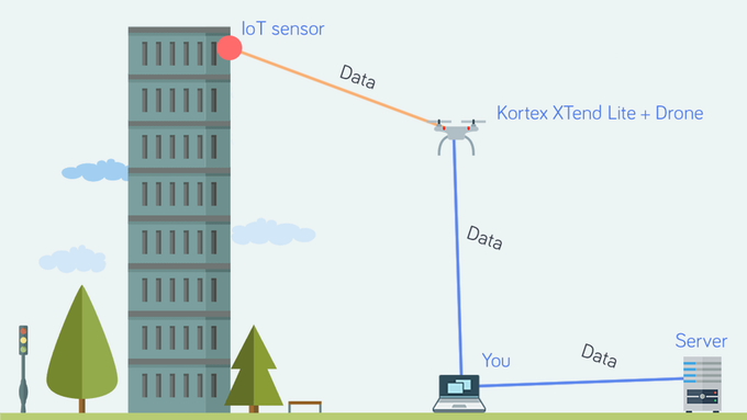
I must say, it also comes with a built-in MQTT client, making you able to technically turn the device into some IoT device capable of connecting to existing infrastructure, monitoring power and data for smart grid systems and so much more.
So what do you get then?
The device comes as a complete package where it is super easy to set-up –
A Kortex Xtend Lite V1.0.0 NAT Repeater
A 6dBi omnidirectional WiFi antenna
A JST male battery connector (comes without battery)
A mini USB cable (optional)
The Kortex Xtend has recently concluded its Kickstarter campaign successfully where he partnered with PCBWay for the PCB development. Although the Kickstarter campaign has ended, you can still subscribe to get notified when the device is ready for market. It is expected to cost around $32. More information is available on the Kickstarter page.
The Chirp Explorer Board is the first IoT prototyping platform that’s tailor-made from the ground up to explore the possibilities of acoustic data transfer.
Built around the powerful Arm Cortex-M4 CPU with inbuilt DSP for optimised audio processing, it allows developers to quickly and easily integrate data-over-sound technology into embedded scenarios. Freely-available reference designs and open-source sample applications make it easy to build a data-over-sound prototype that can be seamlessly scaled to production.
We’ve made it as quick and simple as possible to integrate with the Chirp Arm SDK, with drop-in examples to get you up and running in minutes — no need to wrestle with handling audio I/O manually.
Specifications
Arm Cortex-M4 CPU running at 168MHz, with 256KB RAM and 2MB Flash
High-quality 192kHz audio DAC (Cirrus Logic CS4271) supports data-over-audio transmission in the audible and near-ultrasonic ranges, with a transmission range up to 3m
Integrated MEMs microphone and 1.4W dynamic loudspeaker provide integrated support for sending and receiving Chirp signals
Supports 3.5mm line-level inputs and outputs to connect to external audio peripherals (with optional Molex adapter)
User-assignable RGB LEDs, potentiometers and push buttons
Arduino-compatible GPIO pinout, with 21 GPIO pins, 8-channel 12-bit ADC, 2-channel 12-bit DAC, SPI, CAN, I2C, UART, and several multi-function hardware timers
Powered via micro-USB and programmed via standard SWD interface
Can also be used as a general-purpose development board for audio prototyping
The company says the Chirp Explorer Board will be shipping by the end of this year; however there’s no definitive set date or a perspective price-point. You can sign up for updates and pre-release notifications here for further information.
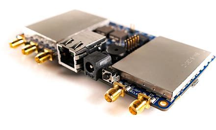
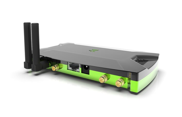
LimeNET Micro is an open spec, 125 x 65mm fully embedded SDR board, featuring the Raspberry Pi Compute Module3, MAX10 FPGA, u-blox GNSS, RF transceiver, Ethernet with PoE, and optional enclosures. It is Lime’s first fully embedded SDR board. The LimeNET Micro will be available for order in Dec. 6, starting at $269, including the integrated Raspberry Pi Compute Module 3, with shipments slated for Feb. 25, 2019. Other packages include adding enclosures and omnidirectional antennas. The new LimeNET Micro mainboard is slightly larger than the 100 x 60mm LimeSDR Mini, and the double enclosure options are about the same size as the Mini enclosure. The Micro enables more compact systems by integrating the 67.6 x 31m Raspberry Pi CM3 module rather than requiring an attached desktop or SBC computer.
The LimeNET Micro is also fitted with an Intel/Altera MAX 10 FPGA with 16k programmable logic gates. It also integrates Lime’s SDR-optimized LMS7002M RF transceiver. The Micro and Mini have similar specs, including the 10MHz to 3.5GHz range, 12-bit sample depth, full-duplex operation, single TX and RX channels, and precision oscillator. The LimeNET Micro RF 0.27MHz bandwidth and 1.0MSPS sample rate are much lower than the LimeNET Mini. This could be due to the lower processing power of the RPi CM3 compared to other attached computers, or to additional onboard components. Like the original RPi 3, the CM3 module has a quad-core -A53 Broadcom BCM2837 clocked to 1.2GHz. It comes with 1GB LPDDR2 and 4GB eMMC. The Micro has a $30 option for an adapter and ribbon cable that allows you to attach a full-sized Raspberry Pi. It’s not clear if the attached SBC plays any role in LimeNET Microprocessing or if it simply enables easier access to I/O features such as WiFi/BT, which are absent on the CM3.
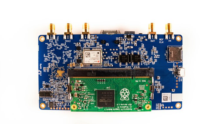
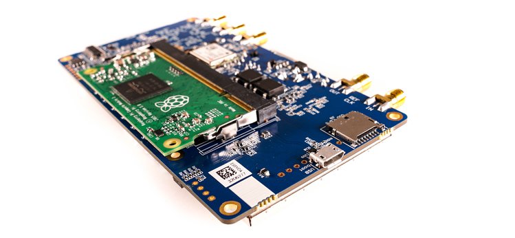
LimeNET Micro with Raspberry Pi Compute Module (bottom)
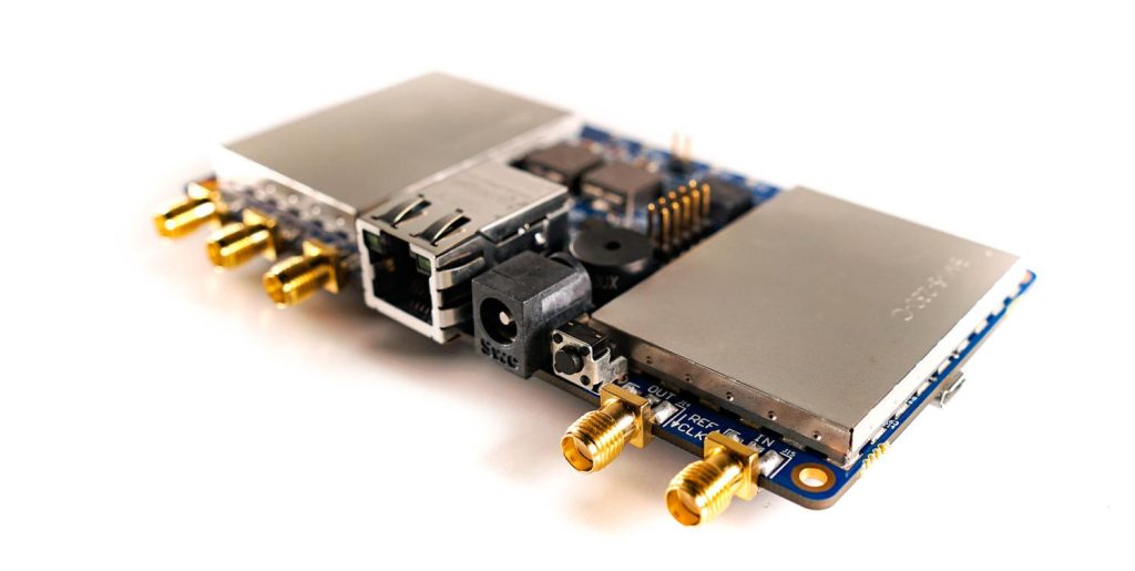
The Micro doesn’t have the full-sized USB port of the earlier Lime boards, but it has a micro-USB for booting, as well as a 10/100Mbps, RJ45 Ethernet port with 12V, passive Power-over-Ethernet (PoE). A microSD slot is also available, and a 12V DC input jack. The Micro has Dual coaxial RF (SMA) connectors for the LMS7002M chip, which can be switched between high- and low frequencies. A pair of omnidirectional antennas is available, which goes for $45, and are optimized for 800-960 MHz, 1710-2170 MHz, and 2400-2700 MHz. The Micro has SMA connectors for external clock source in and out, and for the integrated u-blox NEO-M8 (PDF) GNSS module. This is a first for a Lime board. The -167 dBm sensitive GNSS module supports BeiDou, Galileo, GLONASS, and GPS / QZSS, and can simultaneously receive up to three GNSS signals. For $49, a GPS antenna with a 28 dB gain and 3-meter cable is available.
The Micro is fitted with FPGA-connected GPIO and JTAG connectors, FPGA switches, 6x LEDs, and a buzzer. There’s also a 30.72 MHz VCTCXO clock, and the RF module includes dual 128KB EEPROMs. You can buy the Micro board on its own or one of two enclosures. The $99 acrylic case incorporates a fan and a heatsink. There’s also a $459 aluminum case option available, which unlike the acrylic option, incorporates a RPi CM3 module with dual antennas. The aluminum case has much better noise interference compared to the acrylic case. The aluminum case is the only option that preloads the CM3 with the open source PantaHub container software, which allows you to connect your devices and transform them into bare-metal infrastructure. PantaHub incorporates a Pantavisor device agent and uses container technology to develop, deploy, and manage firmware on Linux devices.
The Micro is an open source product, just like the other Lime systems. It will be made available with schematics, layout and project files, and open Lime Suite firmware code. The Micro supports most of the SDR applications enabled by other Lime products. The Lime systems can send and receive data using UMTS, LTE, GSM, WiFi, Bluetooth, Zigbee, LoRa, RFID, Digital Broadcasting, Sigfox, NB-IoT, LTE-M, Weightless, and any other wireless technology that can be programmed with SDR. They can drive low-cost, multi-lingual cellular base stations and wireless IoT gateways, and are used for various academic, industrial, hobbyist, and scientific SDR applications, such as radio astronomy, which earlier this year, the European Space Agency purchased 200 LimeSDR Mini boards to prototype SDR-enabled 5G satellite networks.
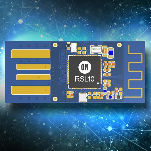
ON Semiconductor’s RSL10 family of Bluetooth 5 certified radio SoCs now supports the Bluetooth SIG mesh networking standard. By Ally Winning @ eenewsembedded.com
The company has also introduced a new PC software application with the RSL10 USB dongle that has software and design support tools to ease development. Along with BLE Explorer software applications, the RSL10 USB Dongle also helps developers scan, connect, and wirelessly interact with prototypes while monitoring and logging behaviour.
Consuming 62.5 nW while in Deep Sleep mode and seven mW peak receive power, RSL10 provides advanced wireless functionality without compromising battery life. The RSL10 radio’s energy efficiency was recently tested using the EEMBC’s ULPMark, where it was the first device to break 1,000 ULP Marks, and it also produced Core Profile scores more than twice those of the previous industry leader.
World’s 1st Headphone to eliminate dizziness for long time wearing | Immersive audiophile sound | Advanced noise cancellation
SHIVR’s own advanced algorithm can effectively enhances audio surround sound and sense of space, allowing the listener to accurately sense sound from different sources.
Traditional two-channel audio only delivers sound from the left and right side, but in real life we can identify sounds from various directions, distances and the surrounding environment. Real sounds mix as they bounce off walls, floors, and ceilings, and gives us a feel of room size and the materials within it.
We use a gyroscope technology-based 3D audio algorithm to achieve 3D spatial sound.
SHIVR’s algorithm deconstructs the sounds from difference sources and rebuilds them in an environment simulator, to determine directions, distances and reflected surface data of the sound.
Head tracking tech keeps the sound locked in position no matter what movements you make with your head.c
By creatively implementing a customized built-in gyroscope we provide a revolutionary comfortable listening experience by eliminating the “in-the-head localization effects. So you won’t feel dizzy after wearing it for a long time.
Most active noise cancelling (ANC) headphones use only one mic to pick up and process the ambient noise. But SHIVR includes both feedforward and feedback mics. This more advanced measurement of sound provides the best noise-free experience in any environment.
The SHIVR headphones are live on kickstarter and has 37 days to go with pledges starting from $119.