Programmable DC Electronic Load Model 63000 Series

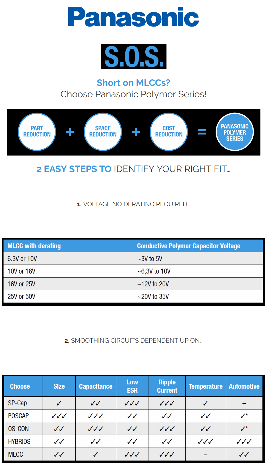
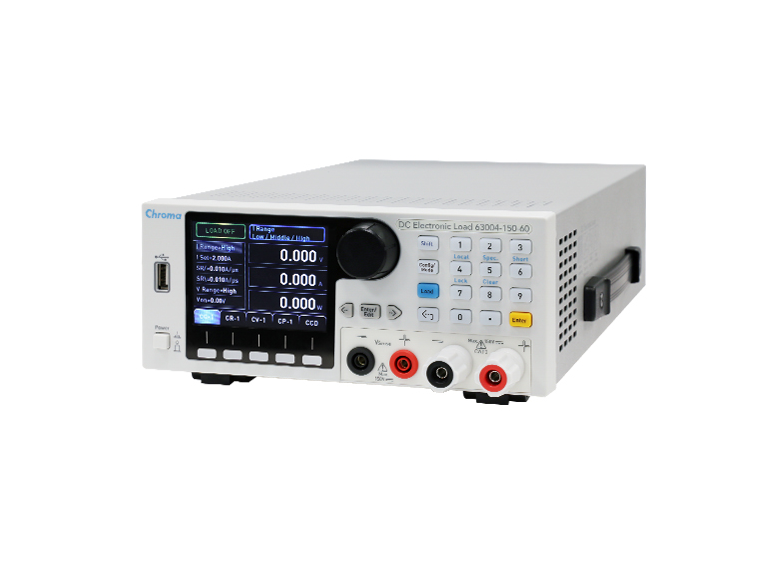
To meet the testing requirements of small power supplies, Chroma has launched a brand new 63000 Series of benchtop DC electronic loads specifically designed for testing lower power adaptors, cell phone chargers, small batteries (such as cell phone batteries), D/D converters, USB PD, and so on. Different from the modular electronic load, they can be used without a mainframe. With the advantages of its compact size, lighter weight, low cost, and portability, the 63000 Series is the perfect electronic load for R&D labs and colleges.

The voltage and current specifications of each model in the 63000 Series are comprised of three settings and three measurement ranges. For adapters and USB PD’s that require higher testing accuracy, small current test like 0.1A is often performed during efficiency testing. However, misjudgment frequently occurs due to insufficient range or low accuracy. The minimum setting and measurement current range of the 63004-150-60 is 2A and the current error is less than 2mA which makes it suitable for these tests and validating the regulatory compliance of Energy Star. The maximum current output of a single load is up to 60A, with power up to 350W. Besides, the large scaled fonts and moderate shortcuts in its 3.5” LCD display bring great usability in the forms of sight and touch.

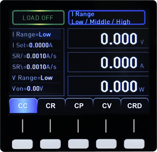
In addition to the basic CC, CR, CP, CV, and CRD modes, the 63000 Series also has battery discharge, User Defined Waveforms (UDW), and programming functions to satisfy the test requirements for D/D converters, 3C battery dischargers, and switching power supplies.

Figure 1 User Defined Waveform – Figure 2 Pulse Current

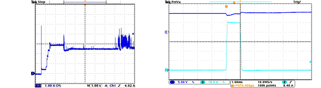
The battery discharge mode is applicable for 3C battery discharge test and can record the Wh (Watt) and Ah (Ah) during battery discharge. The User Defined Waveform (Figure 1) can simulate the real load current allowing the R&D test engineer to verify the power in the actual load current. The quality assurance department can reproduce the actual load current situation to reduce the development and validation time. For other DC power and component applications such as fuel cells, fuses, switches, and wiring tests, the pulse current (Figure 2) function is provided to test them by setting the repeat time to 1 in the existing dynamic loading mode.

Key Features
  • Rated power: 250W, 350W
  • Voltage range: 150V
  • Current range: 60A max.
  • CC, CR, CV & CP operation modes
  • User-defined waveforms (UDW)
  • CZ mode for turn on capacitive loadsimulation
  • Real time power supply load transient response simulation
  • User programmable 100 sequences via front panel
  • High precision voltage & current measurement
  • Voltage, current & Pmax measurement for OCP/OLP test
  • Timing & discharging measurement for batteries
  • Short circuit simulation
  • Smart fan control
  • Full protection: OC (adjustable), OT, OP (adjustable) protection & OV warning, polarity reverse alarm
  • Standard USB, optional Ethernet and GPIB interfaces

For more information about our DC Electronic Loads – 63000 Series, please visit company website: DC Electronic Load Model 63000 Series

Tiny USB to UART Converter using CH330

This is a 10x10mm USB-Uart converter with 2Mbps interface speed based on the cheap CN330. Source files available on GitHub.

CH330(N) works with CH340/CH341 driver as pointed out by Icenowy Zheng who made a small USB to TTL debug board based on the chip to practice PCB drawing with KiCAD. She also mentioned the USB ID and behavior of CH330 is the same with CH340.

A Beginner’s Guide to Circuits

First steps in circuit design for the budding electrical engineer.

San Francisco, CA (October 25, 2018)A Beginner’s Guide to Circuits ($17.95, 80 pp., October 2018) introduces beginners to the magic of electronics. With easy-to-follow instructions, it’s sure to be the perfect book for young readers who want to understand the everyday electronics around them and gain the skills and confidence needed to venture into more advanced STEM projects.

The book opens with an introduction to reading circuit diagrams that shows readers how to connect components on a breadboard, a reusable board with holes for connecting circuit parts without soldering. The book’s nine projects each include a parts list of inexpensive and readily available materials and a detailed diagram to orient the reader as they assemble the circuit step-by-step. Throughout the book, author Øyvind Nydal Dahl shows readers how to apply resistors, transistors, capacitors, and other components to their own circuit designs.

Readers can check their work and troubleshoot malfunctioning circuits by referring to the common mistakes section in each project. Calculations and additional diagrams at the end of chapters explain how circuit components work and ensure that readers fully understand the mechanics behind each project.

The book’s projects include:

  • A touch-enabled light switch made from uninsulated wires
  • An operation-style game that teaches closed loop concepts
  • A blinking LED using an integrated circuit and the basics of digital electronics
  • A digital piano that plays four tones and uses speakers
  • An alarm that buzzes when the light-dependent resistor (LDR) detects light
  • A night-light with a circuit that turns on an LED when it gets dark

A Beginner’s Guide to Circuits is sure to give readers a practical foundation in electronics that will take them further down the path from curious beginner-in-training to imaginative inventor.

Author Bio 

Øyvind Nydal Dahl built his first circuit at age 14 and has been building ever since. Øyvind has a master’s degree in Electronics from the University of Oslo, helps companies develop new products, and travels the world teaching electronics workshops. He is also the author of Electronics for Kids (No Starch Press, 2016). Read more about Øyvind at http://www.build-electronic-circuits.com

About No Starch Press

San Francisco–based No Starch Press has published the finest in geek entertainment since 1994—bestsellers like Python Crash Course, Python for Kids, The Linux Command Line, How Linux Works, and Hacking: The Art of Exploitation. Our titles have personality and attitude, our authors are passionate about their subjects, and our editorial team puts every book through a rigorous process of developmental editing, tech review, design, and production

Run Windows applications on Android

ExaGear is a virtual machine that allows you to run Windows PC applications on ARM Android devices and ARM Chromebooks. Play your favorite old-school games and use your daily PC apps on your phone, tablet or Chromebook – fast and easily. Our unique technology lets you use all of your desktop applications as if they were native apps for your Android device.

ExaGear Windows Emulator offers you one of the easiest ways to run Microsoft Windows software on your Android device without a Windows license or a virtual machine. ExaGear Windows Emulator makes it easy to launch Windows software natively and provides the full functionality via adapted touchscreen controls. The Windows programs (and games) run almost as fast as they would under a real Windows operating system.

Features

  • Run Windows software on Android with no lagging or delays
  • Operate a native Windows desktop file manager
  • Use thought-out adapted and adjustable touchpad controls
  • Enjoy our minimal style user-friendly interface

For now, ExaGear is able to launch the next list of Windows applications and games:

  • Microsoft Office 2010
  • StarCraft
  • Diablo 2
  • Heroes of Might and Magic 3/4
  • Disciples 2
  • Fallout 1/2
  • Sid Meier’s Civilization III
  • Stronghold Crusader
  • Total Annihilation
  • Caesar III
  • ..and much more!

Short on MLCCs? Choose Panasonic Polymer Series

*Only infotainment or non-safety critical circuits


Panasonic has expanded the CS, CT, and CX SP-Cap series to include higher voltage caps with range up to 35V. The newest additions to the SP-Cap product line features high voltage, low profile, high-temperature reflow, and unique electrode materials for high withstanding voltages. The higher voltage SP-Caps are used with DC/DC converters, output signal stabilization, and filtering. Panasonic’s SP-Cap Polymer Organic Aluminum Capacitor is a surface mount aluminum electrolytic capacitor that uses a conductive polymer as its electrolyte in layered aluminum construction. The SP-Cap product line from Panasonic consists of multiple series that offer capacitance range up to 560µF, voltage range from 2VDC to 35VDC, and the lowest ESR/impedance in the industry, achieving very good noise suppression and transient response. Unlike MLCCs, SP-Caps are free from temperature drift and DC/AC bias characteristics. In addition, voltage deration is not needed in SP-Caps, as in tantalum capacitors, due to their safety features. SP-Caps are the perfect solution for input and output capacitor for various DC/DC converters.

VIEW MORE

POSCAP utilizes sintered Tantalum as an anode sytem and highly conductive polymer created with Panasonic’s unique method as a cathode system. This enabled POSCAP to be thin, small and at the same time have low ESR (Equivalent Series Resistance) and superior high frequency characteristics. These features make POSCAP one of the best candidates for digital/high frequency applications. POSCAP also has high reliability and heat resistance.

READ MORE

OS-CON is an aluminum solid capacitor with high conductive polymer. OS-CON acquires low Equivalent Series Resistance (ESR), excellent noise reduction capability and frequency characteristics. In addition, OS-CON has a long life span and its ESR has little change even at low temperatures since the electrolyte is solid.

READ MORE


View whitepaper on polymer capacitors as a replacement for MLCCs

Miniature NanoPi Duo2 Board With Camera Connector

FriendlyElec has launched an upgraded miniature $20 “NanoPi Duo2” board that updates the original Duo with an Allwinner H3, Bluetooth, a camera connector, and an optional 2G carrier board.  NanoPi Duo2 has two 16-pin GPIO headers with breadboard pins in a dual-in-line layout. The Duo2 can be placed into an embedded design like a computer module or it can be plugged into a breadboard or optional carrier board.

The NanoPi Duo2 comes with an optional, $10 IoT-2G Application Carrier Board equipped with a 2G radio, which is specifically designed for the Duo2. The microSD slot and micro-USB OTG port make the Duo2 barely an SBC. The 55 x 25.4mm Duo2 is a bit larger on one end than the 50 x 25.4mm Duo. The extra space houses the new camera connector, which supports a ribbon cable connected to OV5640 based camera.

The 1,397 sq.mm, Duo2 is still one of the smallest Linux-ready SBCs available, even smaller than the 40 x 40mm (1,600 sq. mm) NanoPi Neo line of boards. Some of the latest Neo models are much larger, like the 85 x 56mm, Rockchip RK3399 based NanoPi Neo4. The NanoPi Duo2 switches from an Allwinner H2+ to an Allwinner H3. This has the same four, 1.2GHz Cortex-A7 cores and Mali-400 MP2 GPU, but supports 4K video instead of HD. The Duo2 offers a 256MB DDR3 option, unlike the Duo that offers 256MB or 512MB DDR3.

NanoPi Duo2 layout

There’s an enhanced 802.11b/g/n wireless module, which adds Bluetooth 4.0. However, the Duo2 has a slim 20 to 70℃ operating range than the Duo. An IoT-2G Application Carrier Board, which is set to replace the Duo’s earlier ”Mini Shield” carrier is also available. It is said to be dedicated to the Duo2. The 85 x 56mm IoT-2G board is shaped like a Raspberry Pi board, but it’s restricted to dual USB 2.0 host ports. The board has a “SIM800C” quad-band, 2G GSM/GPRS module and microSIM slot, as well as a 2G antenna and dual 2G status LEDs. There’s also an IPX to SMA antenna converter for a WiFi antenna. The IoT-2G Application Carrier Board is fitted with a power-only micro-USB port and a 10/100 Ethernet port. There’s a debug UART, as well as audio, CVBS, UART, and I2C headers.

Specifications listed for the NanoPi Duo2 include:

  • Processor — Allwinner H3 (4x Cortex-A7 @ up to 1.2GHz); ARM Mali-400 MP2 GPU @600MHz
  • Memory — 512MB DDR3 RAM; empty SPI flash socket
  • Storage — MicroSD slot (bootable) for up to 128GB
  • Wireless — Ampak AP6212 with 802.11b/g/n and Bluetooth 4.0 LE; IPEX antenna connector
  • Other I/O –  Micro-USB OTG port with power input, 2x USB host pins, Audio I/O header, Camera connector that supports OV5640 based camera
  • Debug serial header, 32-pin dual-in-line interface via 2x 16-pin headers (UART, SPI, I2C, audio, Ethernet, IO, etc.)
  • Other features — 2x LEDs; mounting holes; GPIO key; optional IoT-2G carrier
  • Power — 5V/2A DC via micro-USB OTG
  • Operating temperature — -20 to 70℃
  • Dimensions — 55 x 25.4mm; 6-layer PCB
  • Weight — 7.36 g without pin headers
  • Operating systems — FriendlyCore 16.04 (based on Ubuntu Core) with Linux 4.14-LTS kernel and U-boot-2017.11

Further information may be found on the NanoPi Duo2 product page and wiki, as well as the IoT-2G wiki.

Hardkernel ODROID-H2 with Intel Celeron J4105 To Launch soon

Hardkernel started working on an ODROID x86 board since last year, and the board was slated to launch later in 2017 according to the CEO in an interview published in ODROID magazine. After several repetitions, procedures, and processors considerations, the ODROID-H2 is set to become available by November as the first ODROID x86 board. The ODROID-H2 has an Intel Celeron J4105 Gemini Lake processor, two SO-DIMM slots for memory, two SATA ports, M.2 NVMe slot for storage and two Gigabit Ethernet ports. The Odroid-H2 is equipped with a pair each of USB 3.0 and 2.0 ports, as well as a rather scanty 20-pin GPIO connector. Obviously, this is less of an IoT tinkering board than it is of a media and gaming platform.

ODROID-H2 is in the final stage of development and shipment is expected later in November. A series of performance tests were carried out, like the thermal design and power consumption testing of the board with Ubuntu 18.04. The board can stay cool (under 70°C) under heavy load, it consumes 4 watts at idle mode, and up to 22 Watts during a CPU+GPU stress test and 4K 60fps H.265 to 720p H.264 video transcoding can be done faster in real-time with performance improving by 25% when using dual channel RAM configuration. There’s no WiFi, so if you use the M.2 slot for storage, you’ll need to tap one of the four USB ports. There’s a wide-range 14-20V DC input, a power management IC, and a real-time clock. A large heatsink keeps the CPU running smoothly at 2.3GHz even at 70°C. Since the heatsink is high, the design is able to stack the coastline ports in towers like a mini-PC. So what you get has a compact footprint, but also a high profile.

ODROID H2

The company also released a video that shows the board runs Ubuntu 18.10 with Kernel 4.18 from eMMC storage. They ran Dolphin emulator accelerated by Vulkan GPU driver and were capable of smoothly playing Wii games with three players . The price for the device is not known yet, but with LattePanda Alpha board as a competitor, we can get an idea of the price of the Hardkernel ODROID-H2.

ODROID H2 loaded with 8GB RAM and an NVMe SSD

The LattePanda board comes with a similar Celeron N4100 processor, but different to the Hardkernel board, it includes a RAM soldered on the board. The LattePanda Alpha 800 model price is listed as $298 on DFRobot, which includes 8GB LPDDR3 RAM, and active cooling. Based on this price information, and the typical price for Celeron J4105 mini PCs, it is expected the barebone version of ODROID-H2 board to sell for around $180-$200 without accessories due to the fact that it also includes extra features like dual Ethernet, dual SATA, NVMe SSD support, etc, which is not often found in lower cost mini PCs.

The ODROID-H2 board specifications include:

  • SoC: Intel Celeron J4105 quad-core processor @ up to 2.3 GHz (real frequency) with 12EU Intel UHD Graphics 600
  • System Memory: Dual-channel Memory DDR4-PC19200 (2400MT/s) supporting up to 32GiB RAM in total
  • Storage: M.2 PCIe 2.0 x4 slot for one NVMe storage, 2x SATA 3.0 ports, eMMC flash support
  • Video Output: HDMI 2.0 up to 4K (4096×2160) @ 60 Hz
  • DisplayPort: 1.2 up to 4K (4096×2160) @ 60 Hz
  • Audio:  HDMI, audio jacks for HP, MIC. and S/PDIF
  • Connectivity: Dual Gigabit Ethernet (RJ45)
  • Expansion: 20-pin header with I2C and UART (3.3V)
  • Misc: RTC battery
  • Power Supply: 14V to 20V DC power input
  • Dimensions: 110x110x43mm
  • Weight: About 320 grams with a heatsink, two DRAM modules, and M.2 NVMe SSD.

More information can be found on Hardkernel’s Odroid-H2 announcement.

[update 20/11/2018] Hardkernel launched the board today for $111 on their online store with shipments scheduled the start on November 27th.

AVR-IoT WG development board

Microchip released a new IoT Development board, the AVR-IoT WG with part number: AC164160

The AVR-IoT WG development board combines a powerful 8-bit ATmega4808 MCU, an ATECC608A CryptoAuthentication™ secure element IC and the fully certified ATWINC1510 Wi-Fi® network controller – which provides the most simple and effective way to connect your embedded application to Google’s Cloud IoT core platform. The board also includes an on-board debugger, and requires no external hardware to program and debug the MCU.

Out of the box, the MCU comes preloaded with a firmware image that enables you to quickly connect and send data to the Google Cloud IoT platform using the on-board temperature and light sensors. Once you are ready to build your own custom design, you can easily generate code using the free software libraries in Atmel START or MPLAB Code Configurator (MCC).

The AVR-IoT board is supported by two award-winning Integrated Development Environments (IDEs) – Atmel Studio and Microchip MPLAB® X IDE – giving you the freedom to innovate with your environment of choice.

Smart – Expand IoT functionality using the powerful ATmega4808 with 48 KB Flash and 6 KB RAM.
Secure – Entrust encryption to the latest in Microchip’s CryptoAuthentication portfolio, based on ATECC608A.
Connected – Propel your design into the Cloud with Microchip’s ATWINC1510, a single-band 2.4 GHz network controller.

ATmega4808 microcontroller

  • Four user LED’s
  • Two mechanical buttons
  • mikroBUS header footprint
  • TEMT6000 Light sensor
  • MCP9808 Temperature sensor
  • ATECC608A CryptoAuthentication™ device

WINC1510 WiFi Module

On-board nEDBG Debugger

  • Auto-ID for board identification in Atmel Studio and Microchip MPLAB X
  • One green board power and status LED
  • Programming and debugging
  • Virtual COM port (CDC)
  • Two DGI GPIO lines

USB and battery powered

Integrated Li-Ion/LiPo battery charger

TruffleBot Sniffs Out and Accurately Identifies Specific Chemical Odors

TruffleBot identifies smells by measuring small changes in air pressure and temperature. By Megan Scudellari

An electronic nose typically identifies odors by detecting the “fingerprint” of a chemical compound across an array of sensors monitored by pattern-recognition software. E-nose technology is already in use across many industries, including agricultural, environmental, food, manufacturing, and the military.

Electronic sniffers are also being tested for their ability to detect disease, by sensing blood glucose levels from one’s breath and sniffing out gut disease from samples of poop. Better an electronic nose than a real one, right?

At Brown University in Rhode Island, electrical engineer Jacob Rosenstein and colleagues are now taking electronic noses a hop, skip, and a boogie closer to the real thing with a device that actually sniffs odors, sucking up vapors in a premeditated pattern through four pathways, and moving those vapors across chemical and mechanical sensors.

…read more

Review: Siglent SDS1204X-E four-channel oscilloscope

Review: Siglent SDS1204X-E four-channel oscilloscope

Here is a nice mini review of  Siglent SDS1204X-E four-channel oscilloscope by Harry Baggen @ elektormagazine.com:

A few years ago I wrote a review about the Siglent SDS1102X and back then I was very enamoured by the quality and extensive capabilities of this affordable instrument. In the meantime there have appeared a few successors in this series of mid-range oscilloscopes by Siglent and here I’m looking at a somewhat more expensive, four-channel model that has been available since the beginning of 2018, the SDS1204X-E. When it comes to the design and feature set this is very much a continuation of its predecessors. The most conspicuous change compared to the 1100 series is the increased bandwidth of the input stages, these are now 200 MHz (was 100 MHz earlier).

Review: Siglent SDS1204X-E four-channel oscilloscope – [Link]

TOP PCB Companies