Εfficient Wireless Li-Ion Charger with Regulator Optimized for Low Power Wearables

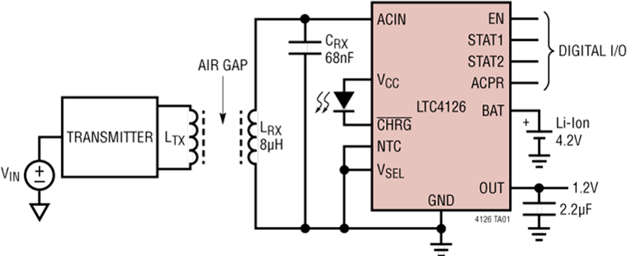
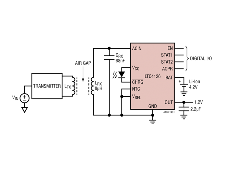
Analog Devices announces the Power by Linear LTC4126, which expands its offerings in wireless battery charging. The LTC4126 combines a wireless powered battery charger for Li-Ion cells with a high efficiency multi-mode charge pump DC/DC converter, providing a regulated 1.2V output at up to 60mA. Charging with the LTC4126 allows for a completely sealed end product without wires or connectors and eliminates the need to constantly replace non-rechargeable (primary) batteries. The efficient 1.2V charge pump output features pushbutton on/off control and can directly power the end product’s ASIC. This greatly simplifies the system solution and reduces the number of necessary external components. The device is ideal for space-constrained low power Li-Ion cell powered wearables such as hearing aids, medical smart patches, wireless headsets, and Internet of Things (IoT) devices.

The LTC4126, with its input power management circuitry, rectifies AC power from a wireless power receiver coil and generates a 2.7V to 5.5V input rail to power a full-featured constant-current/constant-voltage battery charger. Features of the battery charger include a pin selectable charge voltage of 4.2V or 4.35V, 7.5mA charge current, automatic recharge, battery temperature monitoring via an NTC pin, and an onboard 6-hour safety charge termination timer. Low battery protection disconnects the battery from all loads when the battery voltage is below 3.0V. The LTC4126’s charge pump switching frequency is set to 50kHz/75kHz to keep switching noise out of the audible range, ideal for audio related applications such as hearing aids and wireless headsets.

Features

  • Wireless Li-Ion Battery Charger with High Efficiency Multi-Mode Charge Pump DC/DC
  • Wideband Wireless Receive Power Frequency: DC to >10MHz
  • Integrated Rectifier with Overvoltage Limit
  • Pin Selectable Charge Voltage: 4.2V or 4.35V
  • Fixed 7.5mA Charge Current
  • Low Battery Disconnect (3.0V)
  • NTC Pin for Temperature Qualified Charging
  • 1.2V DC/DC Regulated Output at Up to 60mA
  • 50kHz/75kHz Switching, No Audible Noise
  • Pushbutton and/or Digital on/off Control for DC/DC

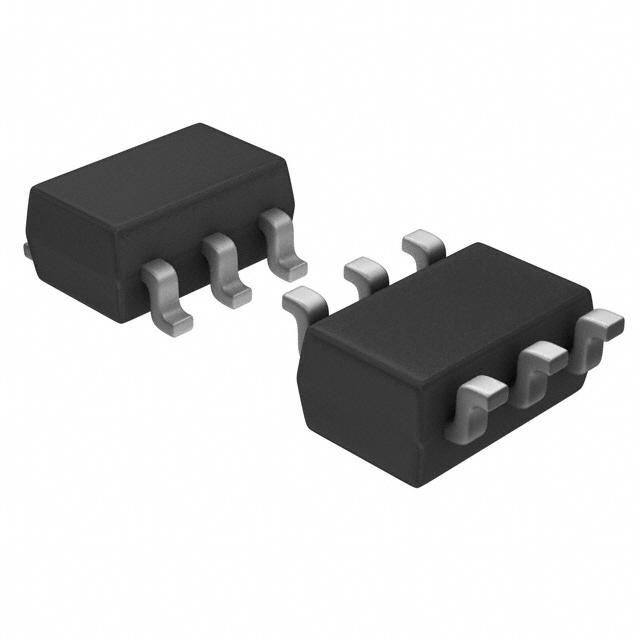
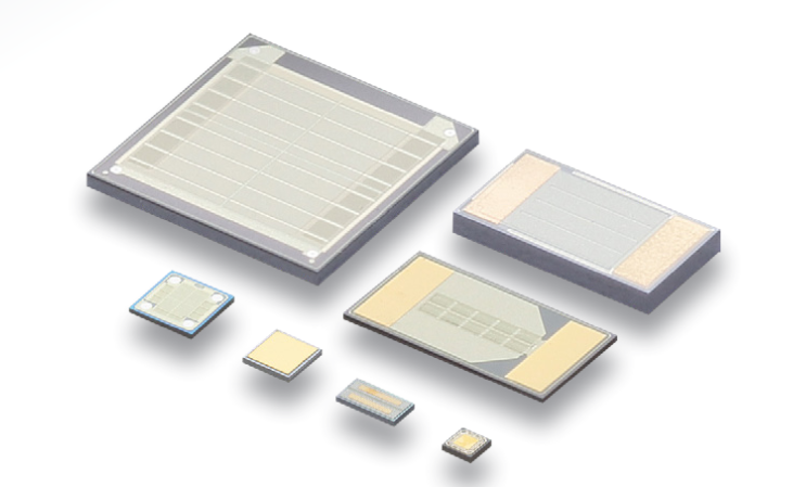
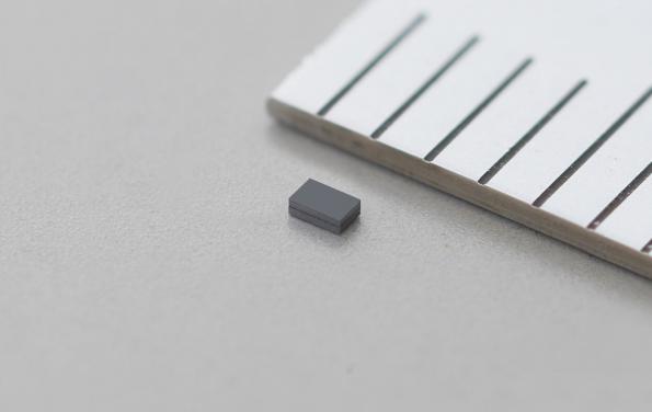
The LTC4126 is housed in a highly compact, low profile (0.74mm) 12-lead 2mm × 2mm LQFN package. The device is guaranteed for operation from –20°C to 85°C in E-grade. For more information, visit www.analog.com/LTC4126

The USB-C Explorer helps to get started with USB-C

The USB-C Explorer

Jason has designed a development board for USB-C and Power Delivery, that is available on GitHub. The board is also on sale at Tindie for $79 + shipping.

The USB-C Explorer is a development board with everything needed to start working with USB Type-C. It contains a USB-C port controller and Power Delivery PHY chip, a microcontroller, and several options for user interaction.

The default firmware will identify as a USB Power Delivery Sink and list out all power capabilities from a corresponding Source. It will then request the highest power option. This voltage will be available on the power header. The example photo shows the capabilities of an Apple MacBook 87W Charger.

The USB-C Explorer helps to get started with USB-C – [Link]

Using a Raspberry Pi to program an ATTiny10/9/5/4

Using a Raspberry Pi to program an ATTiny4/5/9/10. But, mostly the $0.25 ATTiny10. And, not necessarily a Raspberry Pi, but anything with GPIOs!

Yep. It works. At least tested pretty thoroughly with my ATTiny10. It can also read all the memories AND run timings against the AVR to do processor clock calibration, as well as fuses and manual poking to flash en post to allow for custom configuration.

This was actually written in two days for Unit-E Technologies and is made available freely. This project is licensable via the newbsd license.

Get your Things on the Internet in 30 seconds with the AVR-IoT!

RS Components will stock Microchip’s AVR microcontroller IoT development board for Google Cloud, which enables the fast prototyping of cloud-connected devices. By Ally Winning [via]

The Microchip AVR-IoT WG development board uses an ATmega4808 AVR-based MCU, with a ATECC608A CryptoAuthentication IC and a fully certified Wi-Fi network controller. The board works with Google Cloud IoT Core, which offers an artificial intelligence and machine learning based infrastructure and enables the simple collection, processing and analysis of data, as well as a being a scalable platform for IoT applications.

Developers can add cloud connectivity to a device via a free online portal. Once an IoT device is connected to Google Cloud, engineers can develop and debug applications in the cloud using tools such as Microchip’s MPLAB Code Configurator (MCC) or Atmel START.

The ATmega4808 processor is an 8-bit MCU that features Core Independent Peripherals (CIPs) to deliver low power consumption. It also offers advanced sensing and robust actuation features. The ATECC608A CryptoAuthentication IC comes pre-registered on Google Cloud IoT Core and is ready for use with zero touch provisioning.

More informatio: https://uk.rs-online.com & http://www.AVR-IoT.com

Murata’s 3D Silicon Capacitors

Murata high-density silicon capacitors are developed with a semiconductor MOS process and are using the third dimension to substantially increase the capacitor surface and thus its capacitance without increasing the capacitor footprint. Murata silicon technology is based on a monolithic structure embedded in a monocristalline substrate (single MIM and multi MIM – Metal Insulator Metal).

Higher performance in a smaller package

This advanced 3D topology gives a developed area equivalent to 80 ceramic layers in an amazing 100 µm thickness (lower value on request) of active capacitance area. Thanks to a very linear and low dispersive dielectric, miniaturization, capacitance value and electrical performances are optimized.

more info: www.murata.com

32.768 kHz MEMS resonator is only 0.9×0.6×0.3mm

Measuring just 0.9×0.6×0.3mm (50 % smaller than a conventional 32.768 kHz crystal resonator), the WMRAG series 32.768 kHz MEMS resonator is the world’s smallest, claims manufacturer Murata.

Murata Manufacturing Co., Ltd. (Head Office: Nagaokakyo-shi, Kyoto; Chairman of the Board and President: Tsuneo Murata) has developed the world’s smallest 32.768kHz MEMS resonator, which is expected to make a significant contribution to reducing the size and power consumption of IoT devices, wearables, and healthcare devices.

While achieving miniaturization through MEMS technology, the new MEMS resonator exhibits frequency temperature characteristics of less than 160ppm (Operating temperature: -30 to 85°C ) with an initial frequency accuracy (25°C ) that is comparable to or better than that of a quartz tuning fork crystal resonator.

Key features

Over 50% smaller than conventional tuning fork quartz crystal resonators

With dimensions measuring 0.9 x 0.6 x 0.3mm (width, length, height), the new MEMS resonator is more than 50% smaller*6 than a conventional 32.768kHz tuning fork crystal resonator.

Built-in load capacitors

A typical pierce-type oscillator circuit design uses two external multilayer ceramic load capacitors.  The new MEMS resonator is equipped with built in load capacitors, which makes possible a reduction in external parasitic capacitance, mounting space, and further contributes to more flexible circuit design.

Reduced power consumption by realizing a low ESR

With crystal resonators in general, the ESR tends to rise as the device becomes smaller in size. However, with a low ESR (75kΩ) the MEMS resonator can generate a stable reference clock signal by reducing the IC gain while also cutting power consumption by 13% compared to a conventional quartz crystal. (Based on internal tests)

Can be built into an IC package

With silicon-based wafer-level chip scale packaging (WLCSP), the resonator can be co-packaged with an IC, eliminating the need for any external low-frequency clock references.

Murata –  www.murata.com

AdTech Ad

Increase data storage of your Raspberry Pi development board

Connect an mSATA drive to your development board, to increase its data storage capacity. [via]

Increase the data storage capacity of your Raspberry Pi or other development board, by connecting it directly to an mSATA drive. Perfect for custom projects and applications, this USB to mSATA converter supports all models of Raspberry Pi as well as other development boards.

This convenient USB 2.0 mSATA converter lets you overcome data storage limitations by enabling you to connect an mSATA drive through your board’s USB-A port.

The USB to mSATA converter integrates seamlessly with your existing development board. It’s the perfect addition for development-board based applications such as surveillance, media players and servers, digital signage and IoT/automation solutions. It allows you to utilize your mSATA drives with your development board, and take advantage of the small form factor of mini-SATA, ideal for applications with space limitations.

CH3330N – Small and Cheap USB-Serial Converter IC Needs No Crystal

Recently the hobbyist market has seen the appearance of the Air602 low-cost ARM WiFi module. This module might be a potential competitor of ESP8266, another low-cost powerful WiFi module, that took the electronics hobbyists by storm long ago and is still extremely popular. But what’s more interesting about the Air602 module is the usage of a completely new USB to Serial Chip – WCH CH330N. This chip has features similar to CH340, but fewer pins (e.g. DTS, and  CTS are missing), and available in a tiny SOP8 package.

photo: lcsc.com

Here is a brief explanation about USB to Serial chip and what is its usage. A USB to Serial converter converts USB (Universal Serial Bus) signal to UART (Universal Asynchronous Receiver Transmitter) signal and vice-versa. Most 8-bit and 16-bit low-cost microcontrollers do not feature built-in USB stack, rather they have UART peripheral. So, in order to establish communication between a PC that features USB and a microcontroller that only has UART, a converter is used.

UART Signal - Captured using logic analyzer
UART Signal – Captured using a logic analyzer


USB Signal - Captured using logic analyzer
USB Signal – Captured using a logic analyzer

CH330N is catching the attention of tinkerers for its small 8-pin-only form factor, built-in crystal oscillator, and compatibility with CH340 drivers. The CH340 (or CH340G) is yet another USB to Serial converter IC that has been popular for a long period of time. It has a higher pin count compared to CH330N and also supports CTS and DTS, but requires external oscillator circuitry in order to work. The CH330N, on the other hand, is way cheaper than the CH340 and requires only a few external components. This USB to Serial converter supports baud rate from 50 bps to 2 Mbps. The following schematic diagram shows the application of CH330,

CH330 Schematics
CH330 Schematics

This little fellow costs only $0.3535 when order quantity is within 10 pieces, but if you purchase more than 120 pieces, it becomes $0.2829 only. You can purchase from LCSC – a China-based electronics components seller and my personal favorite for their wide range of products, lower price range, and very low shipping charge. The datasheet is in Chinese and can be found here.

NanoPi NEO4 The World’s Cheapest and Smallest RK3399 Board

FriendlyELEC has announced a new board with NanoPi NEO4, the smallest and cheapest RK3399 board on the market presently. The NanoPi Neo4” SBC is a 60 x 45mm footprint, WiFi/BT, GbE, USB 3.0, HDMI 2.0, MIPI-CSI, a 40-pin header, and -20 to 70℃ support, but only 1GB of RAM.

The SBC is set at $45 promotional price ($50 standard). The similarly open-spec, Linux and Android-ready NanoPi Neo4, however, is not likely to outdo the NanoPi M4 on performance, as it has only 1GB of DDR3-1866 instead of 2GB or 4GB of LPDDR3. This is the first SBC built based on the hexa-core RK3399 that doesn’t offer 2GB RAM at a minimum.

The NanoPi Neo4 has a pair of up to 2GHz Cortex-A72 cores and four Cortex -A53 cores clocked to up to 1.5GHz plus a high-end Mali-T864 GPU. The size was probably a major factor in limiting the board to 1GB coupled with its price. The 60 x 45mm size, places the RK3399 into new space-constrained environments. The Neo4 is Still, larger than the earlier 40 x 40mm Neo boards or the newer, 52 x 40mm NanoPi Neo Plus2, which is based on an Allwinner H5.

The NanoPi Neo4 is different from other Neo boards due to the fact that it has a coastline video port, in this case, an HDMI 2.0a port with support for up to 4K@60Hz video with HDCP 1.4/2.2 and audio out. Another Neo innovation is the 4-lane MIPI-CSI interface for a 13-megapixel camera input. A variety of Linux and Android distributions can be booted from the microSD slot or eMMC socket (add $12 for 16GB eMMC).

A native Gigabit Ethernet is also available. There’s also a wireless module with 802.11n, limited to 2.4GHz WiFi and Bluetooth 4.0. The NanoPi Neo4 is fitted with USB 3.0 and USB 2.0 host ports plus a Type-C power and OTG port and an onboard USB 2.0 header. The latter is found on one of the two smaller GPIO connectors that supports the usual 40-pin header, which like other RK3399 boards, has no claims of Raspberry Pi compatibility. Other features include an RTC and -20 to 70℃ support.

Specifications for the NanoPi Neo4 include:

  • Processor: Rockchip RK3399 (2x Cortex-A72 at up to 2.0GHz, 4x Cortex-A53 @ up to 1.5GHz); Mali-T864 GPU
  • Memory: 1GB DDR3-1866 RAM, eMMC socket with optional ($12) 16GB eMMC, MicroSD slot for up to 128GB
  • Wireless: 802.11n (2.4GHz) with Bluetooth 4.0; ext. antenna
  • Networking: Gigabit Ethernet port
  • Media: HDMI 2.0a port (with audio and HDCP 1.4/2.2) for up to 4K at 60Hz 1x 4-lane MIPI-CSI (up to 13MP);
  • Other I/O: USB 3.0 host port, USB 2.0 Type-C port (USB 2.0 OTG or power input) USB 2.0 host port
  • Expansion: GPIO 1: 40-pin header — 3x 3V/1.8V I2C, 3V UART, SPDIF_TX, up to 8x 3V GPIOs, PCIe x2, PWM, PowerKey, GPIO 2: 1.8V 8-ch. I2S, GPIO 3, Debug UART, USB 2.0
  • Other features: RTC; 2x LEDs; optional $6 heatsink, LCD, and cameras
  • Power: DC 5V/3A input or USB Type-C; optional $9 adapter
  • Operating temperature: -20 to 70℃
  • Dimensions: 60 x 45mm; 8-layer PCB
  • Weight: 30.25 g
  • Operating system: Linux 4.4 LTS with U-boot 2014.10; Android 7.1.2 or 8.1 (requires eMMC module); Lubuntu 16.04 (32-bit); FriendlyCore 18.04 (64-bit), FriendlyDesktop 18.04 (64-bit); Armbian via third party.

More information can be found on NanoPi Neo4 product page and wiki.

2.13″ 212 x 104 Three Color E-Ink Paper with SPI

DisplayModule introduced a tiny 2.1″ E-paper display with 212×104 pixels resolution and three colors. The display can be interfaced using SPI and a Raspberry Pi shield is available for the ones that what to connect it to the popular SBC.

Main features

  • Three Color E-Ink
  • 2.13 Inch is  suited to  E-Label.
  • 212×104 resolution  E-Ink raw display
  • No back-light, keeps displaying content forever even no power supply
  • Easy to use, displays any contents via SPI interface, including geometric graphics, texts, and images
  • Ultra low power consumption, basically power is only required for refreshing
  • It is easy working on Respberry Pi with DM-ADTPI-013 (RESE:A; BS:0)

more info: www.displaymodule.com

TOP PCB Companies