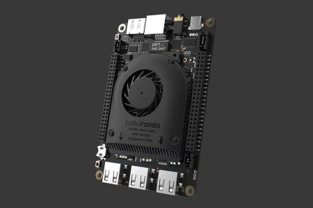
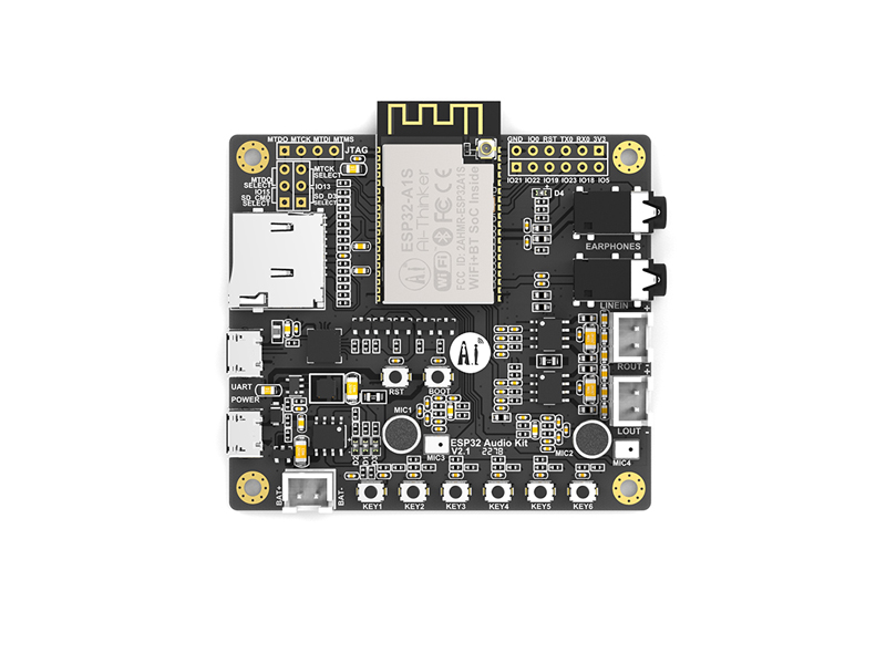
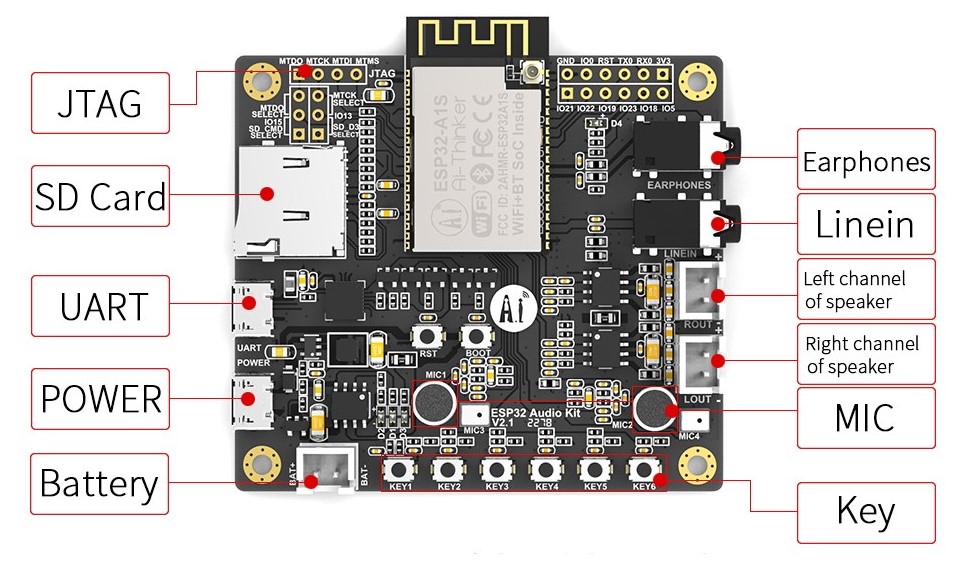
ESP32-A1S is an ultra-small multi-functional audio module. It adopts ESP32 with dual-core processor as the main control. The main frequency is up to 600DMIPS. The module is internally equipped with 4M PSRAM and CodeC audio processing chip, which can be widely used for IoT.
ESP32-Audio-kit is a small size audio development board based on ESP32-A1S from Ai-Thinker, most of the interfaces are distributed at the edges. Supports TF card, LINEIN and 2-way Mic input; support 1 channel headphone output and 1 chanel left and right speaker output, facilitate rapid development, can be widely used in various IoT applications, suitable for home smart devices, smart Audio, story machine solutions, etc.
Features
Low power dual core 32-bit CPU,can also serve the application processor
Up to 240MHz clock speed,Summary computing power up to 600 DMIPS
Built-in 520 KB SRAM, external 8MPSRAM
Supports UART/SPI/I2C/PWM
3.5mm headphone jack, support left and right chanel output.
left/right channel of speaker, support max 4Ω3W output
Support LINEIN and 2-way Mic input
Support 3.7V Li-ion battery or up to 5V2A power input, support battery charging
Support 64G SD card; 6 onboard buttons
Supports multiple sleep modes
Embedded Lwip and FreeRTOS
Supports STA/AP/STA+AP operation mode
Support Smart Config/AirKiss technology
Support secondary development
The board in on sale for 16.90 USD, found on seeedstudio.com
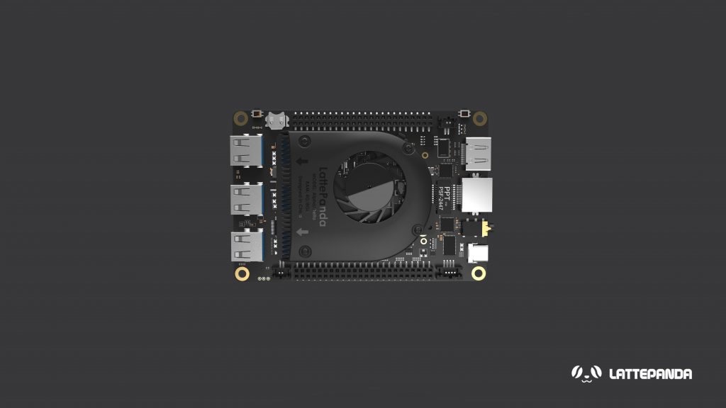
After several months of delay, DFRobot is shipping its Kaby Lake based LattePanda Alpha SBC model, with 8GB RAM and 64GB eMMC with OS support for Windows 10 or Ubuntu 16.04 LTS. Public sales have moved from pre-order to in-stock fulfilment for at least one model. Just like the earlier Intel Cherry Trail based LattePanda, the LattePanda Alpha is significant for being a community-backed hacker board loaded with Windows 10, but it is not fully open source.
LattePanda Alpha 864
With the LattePanda Alpha, there is the option of a cheaper barebones version that supports an optimized, downloadable Ubuntu 16.04 LTS image. It seems that the only LattePanda Alpha model currently in stock and only at DFRobot is the $358 barebones version with 8GB LPDDR3 and 64GB eMMC. A $298 barebones model without the 64GB eMMC and a $398 model with 64GB eMMC and Windows Pro 10 are both listed as pre-order, without a specified shipment date.
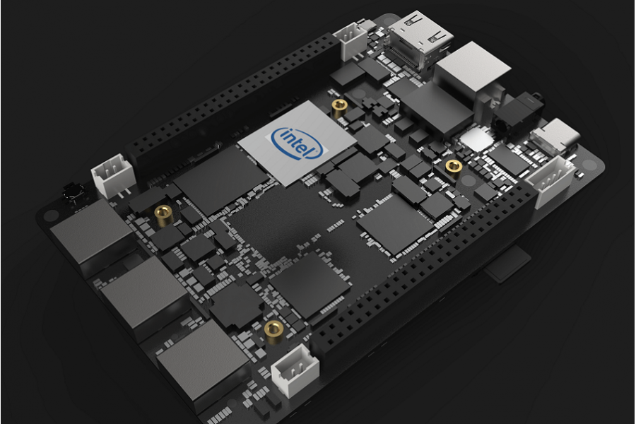
The $358 price for the Linux-ready model is $60 to $70 more than the original Kickstarter packages. The LattePanda Alpha’s 7th Gen Kaby Lake Core m3-7Y30 is a dual quad-thread 1.6GHz/2.6GHz processor with 900MHz Intel HD Graphics 615. The processor has a configurable TDP of 3.75W to 7W, and like the original LattePanda, has an Arduino-compatible co-processor.
LattePanda Alpha 864
There’s also a microSD slot and an M.2 M Key interface that supports PCIe x4, SATA SSD, and NVMe SSD expansion. The Alpha is also fitted with an M.2 E-Key slot with PCIe x2, USB 2.0, I2C, and UART support. This gives additional wireless options in addition to the standard dual-band 802.11ac, which is accompanied by Bluetooth 4.2. A GbE port is also onboard. The Alpha provides 3x USB 3.0 host ports and a USB Type-C port with support for USB 3.0, power input, and DisplayPort. Dual simultaneous 4K display support is accessible through the Type-C DisplayPort, as well as an HDMI port and eDP interface that supports optional 7- and 10.1-inch touchscreens. Other features include a 12V input, an audio jack, a PMIC, an RTC, and a cooling fan. Also, the dual 50-pin GPIO connectors include one with an Arduino pinout.
There are no specific dimensions for the SBC yet. One key feature of the Alpha is a streaming cable that enables Linux, Mac, or Windows desktop users to plug the LattePanda into a USB port that provides easy access to a Windows device and does not need partitioning or dual booting. The streaming settings which enables a PiP (Picture in Picture) view for smooth interaction, is designed primarily for Linux and Mac developers who want to develop Windows 10-based IoT devices.
Various options of the barebones version loaded with Ubuntu are also available in the market and more information can be found on the DFRobot LattePanda shopping page.
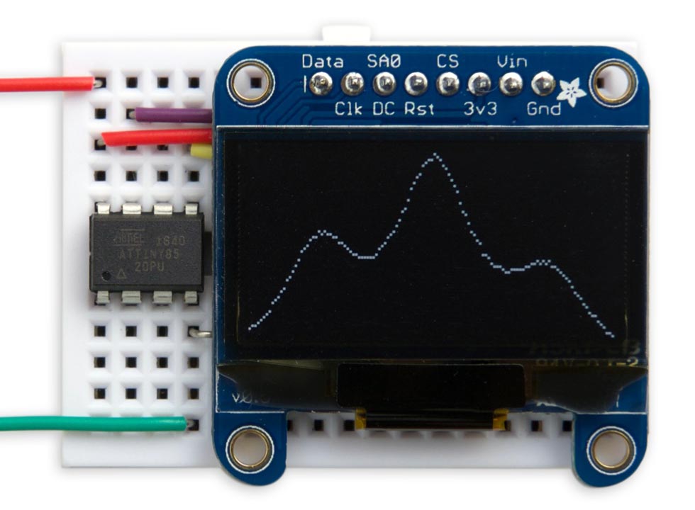
David Johnson-Davies build a OLED display function plotter based on ATtiny85 microcontroller. He writes:
This project describes a simple routine for plotting a function on a 128×64 I2C OLED graphics display. Unlike most Arduino graphics libraries this routine doesn’t require a RAM buffer, and so will work on any processor down to an ATtiny85:
The routine will work on monochrome 128×64 I2C OLED displays based on either the SSD1306 driver, such as the display available from Adafruit, or the SH1106 driver, used in displays available from Chinese suppliers.
At Spectra, Particle’s annual conference, they announced three new products designed to improve enterprise-level IoT development. They are bringing IoT to maturity with total development, deployment, and maintenance platform that goes all through to the enterprise level by design. The 3 new products include: The Particle IoT Rules Engine,Particle Workbench, and Particle Mesh SoMs.
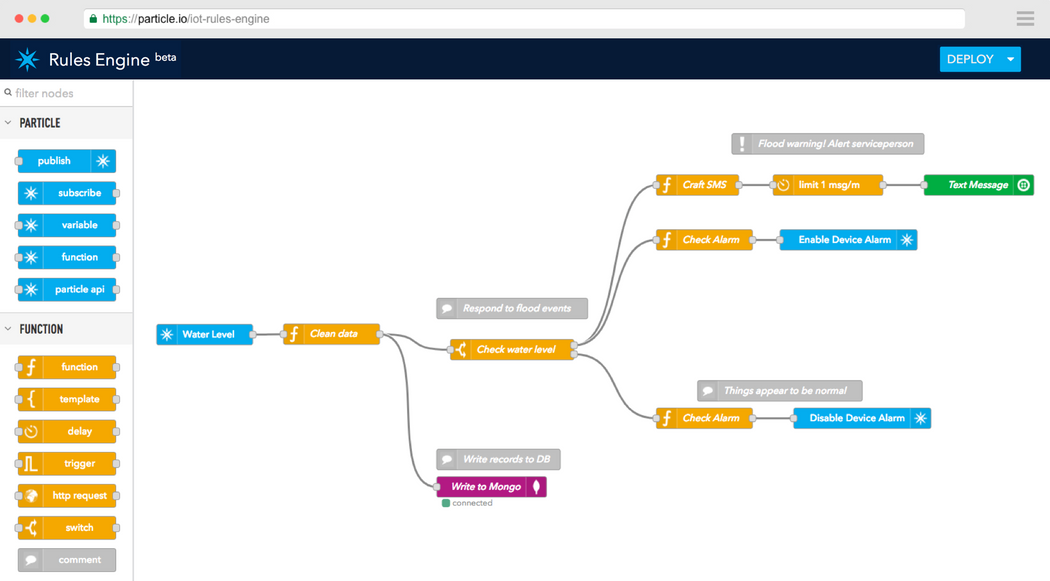
The Particle IoT Rules Engine is a visual drag-and-drop IoT application builder, built on Node-RED open-source platform. You don’t have to spend hours writing a simple IoT application, you can just use the IoT Rules Engine to drop a few blocks into place, and be done in a couple of minutes. It makes it easier for any IoT product developer to create app logic – and get their product to market faster.
Particles rules engine visual interface
This is possible through using if-this-then-that style logic – enabling customers to create business rules in the cloud that react to events in the physical world. The difficult aspect of IoT application development is in the essential details, like reading and processing sensor data or integrating third-party APIs. But the building blocks take care of those details, also coupled with the fact that IoT Rules Engine is built on IBM’s Node-RED tool, thousands of logic snippets developed by the community are available for use.
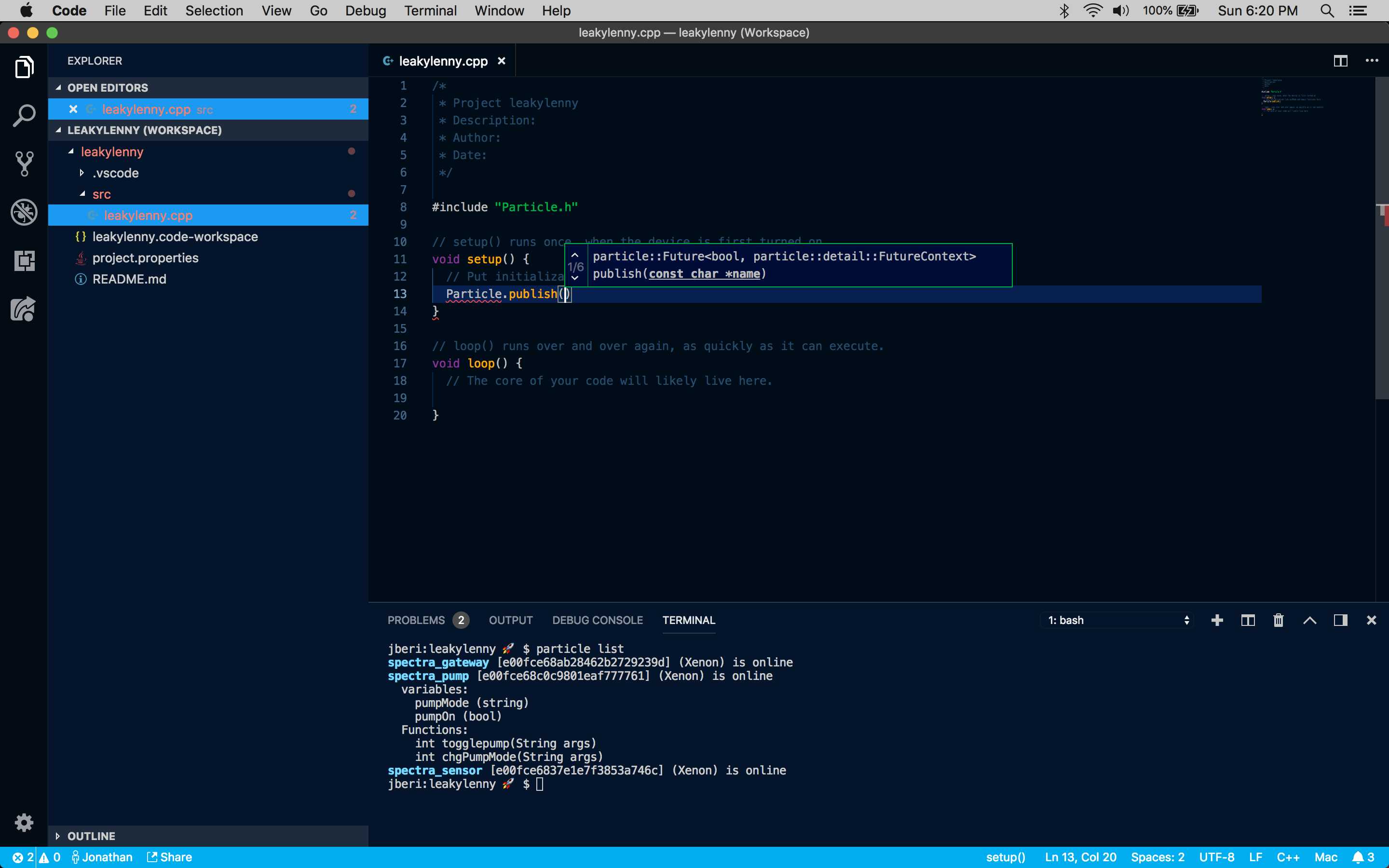
Particle Workbench is powered by Microsoft Visual Studio Code that runs on Windows, macOS, and Linux. It is a cross-platform desktop development environment which creates a robust desktop experience to build and debug professional-grade apps optimized for Particle developers. Particle Workbench gives access to over 3,000 official libraries, plus another 8,000+ extensions in the Visual Studio Marketplace.
Particle Workbench powered by Visual Studio Code
It has an intelligent autocomplete feature through Intellisense and local compilation. No need to code in one editor and then deploy the code in a separate interface anymore, you can do it all from Particle Workbench.
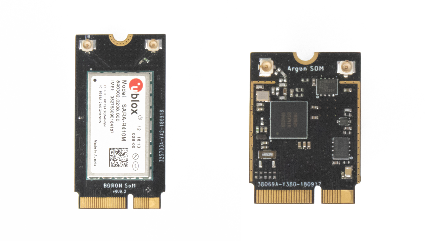
Particle is releasing two new mesh SoMs, the A Series and the B Series. The A Series is identical to the Particle Mesh Argon development board, and has onboard Wi-Fi and mesh networking. The B Series is like the Particle Mesh Boron, and includes built-in LTE and mesh networking. Both modules share the characteristics of their older models, but don’t have large breakout board and pins.
Particle Mesh SOMs
This makes them perfect for use in mass production. Particle is accepting requests to join the limited beta releases of the Particle IoT Rules Engine and Particle Workbench. More details about the A Series and B Series SoMs will be released soon.
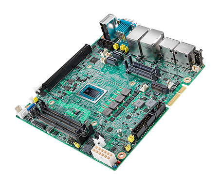
Advantech announced a new gaming and lottery board, the DPX-E265. The gaming board is based on AMD’s Ryzen V1000, which features a 4x DP++ ports, 2x SATA, plus M.2, PCle x16, and PCIe x4 expansion. Prior to the DPX E265, in February of this year Advantech announced the DPC-E140 casino gaming board with AMD’s Ryzen Embedded V1000.
DPX E265 Gaming SBC
They also launched an Intel 7th Gen “Kaby Lake” based DPX-S445 casino gaming SBC in August, which was a follow up of the DPC-E140. The E265 is a lower-end gaming board, which focuses on gaming and lottery applications that fall short of extensive security and I/O features of the DPC-E140. The DPX-E265 has a smaller size than the DPC-E140.
The DPX-E265 has a remodeled Mini ITX surface area of 185 x 170mm, and the I/O ports are stacked. It runs on Windows 10, or Linux operating system and it supports up to 32GB DDR4-2666, with support for ECC RAM. The DPC-E140 is featuring 12C port with RTC, intrusion monitoring, event logging and a couple of other security features, like a standard TPM chip, secure boot, watchdog, and write-protectable BIOS in a removable module.
The DPX-E265 is fitted with 2x RS232 ports, 2x RS232 headers, and an RS232/RS485. There are 3x USB 3.0 ports, 2x USB 2.0 ports. Three standard audio jacks stand-in for the earlier model’s HD 5.1 audio with stereo amplified with 20W outputs. The DPX-E265 provides a PCIe x16 Gen 3 slot and a PCIe x4 Gen 1 slot. The PCle x16 Gen 1 slot is available as a golden finger edge connector that supports “2x full PCIe x1 Gen 1.0 ports (non-standard x4 pin definition) and 2 x USB 2.0.” The DPX-E265 also adds an LPC interface. The DPX-E265 board provides 4x DP++ 1.4 ports with 4K support, one of the ports supports HBR video.
Available also is CFast and dual SATA 3.0 storage, an M.2 slot (2280), and dual GbE ports with PXE, but not WoL. The 12V board supports 0 to 50°C temperature range. Custom features include custom FPGAs or MCUs or additional security features.
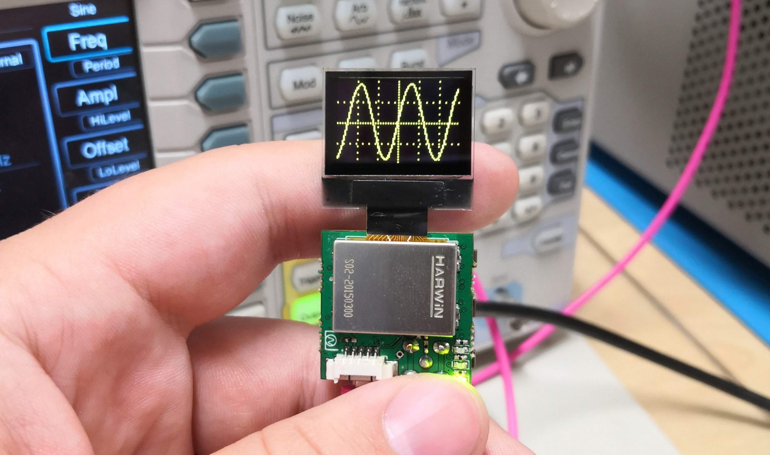
A 1″ by 1″ 20msps Oscilloscope based on the PIC32MZ @ hackaday.io by “Mark Omo”. He writes:
This project is designed around a PIC32MZ EF processor. We use its internal ADCs in an interleaved mode in order to get the full 20Msps. We have found that in practice we are able to achieve approximately 1MHz of bandwidth.
The very first thing that happens is our signal goes into a 1M ohm terminator that also divides down our signal by 10X, allowing us to measure signals outside of the rails (up to around 30V Pk-Pk or ±15V). The very next thing that happens is the signal is passed through a pair of diodes connected to the rails that clamps the voltage to the rails preventing damage.
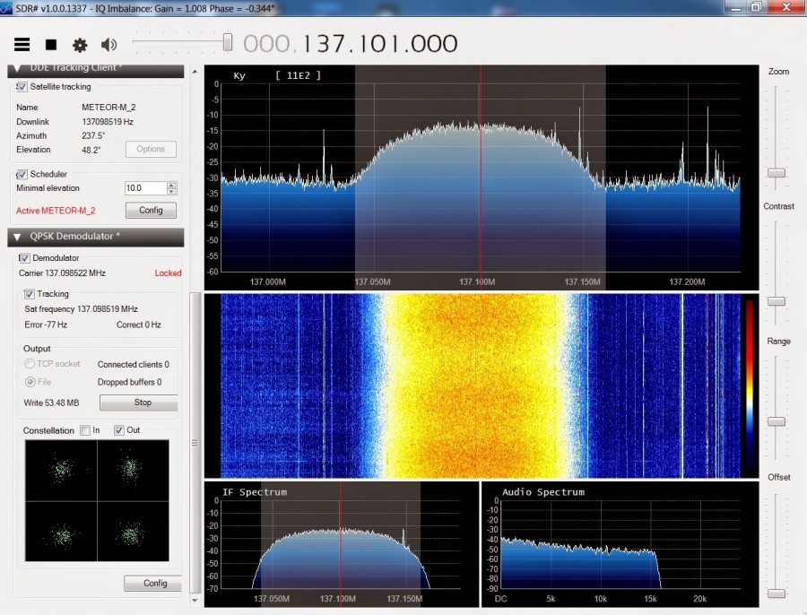
The Meteor-M N2 is a polar orbiting Russian weather satellite that was launched on July 8, 2014. Its main missions are weather forecasting, climate change monitoring, sea water monitoring/forecasting and space weather analysis/prediction. Meteor-M N2 transmits images using the digital LRPT protocol at around 137.1 MHz with can be received with an RTL-SDR. The chipset of RTL dongles was created with the intention of doing DVB-T (digital TV) and DAB (digital radio) demodulation , however a curious linux developer named Antti Palosaari, discovered that these cheap TV adapters are actually Sofware Defined Radios (SDR)!
Decoding Russian Meteor-M2 satellite images in real time – [Link]
While building microcontroller based projects, there are occasions where communication will be required between two devices, either in a duplex/transceiver based operation (where both devices can transmit and receive at the same time) or in a simplex-based operation where communication is one way (Receiving device cannot transmit and the transmitting device cannot receive).
Several options exist for implementing any of the two communication modes mentioned above and the selection of a particular option, usually depends on the specification of the project, especially the distance between the devices and cost. For short range, low-budget communication between two microcontrollers, one of the most preferred medium used is Radio Frequency (RF) communication using the 433MHz RF transmitter and receiver modules. For today’s tutorial, we will look at how to use these modules to establish communication between two Arduino boards.
Using the 433MHz RF Transmitter and Receiver with Arduino – [Link]
While building microcontroller based projects, there are occasions where communication will be required between two devices, either in a duplex/transceiver based operation (where both devices can transmit and receive at the same time) or in a simplex-based operation where communication is one way (Receiving device cannot transmit and the transmitting device cannot receive).
Several options exist for implementing any of the two communication modes mentioned above and the selection of a particular option, usually depends on the specification of the project, especially the distance between the devices and cost. For short range, low-budget communication between two microcontrollers, one of the most preferred medium used is Radio Frequency (RF) communication using the 433MHz RF transmitter and receiver modules. For today’s tutorial, we will look at how to use these modules to establish communication between two Arduino boards.
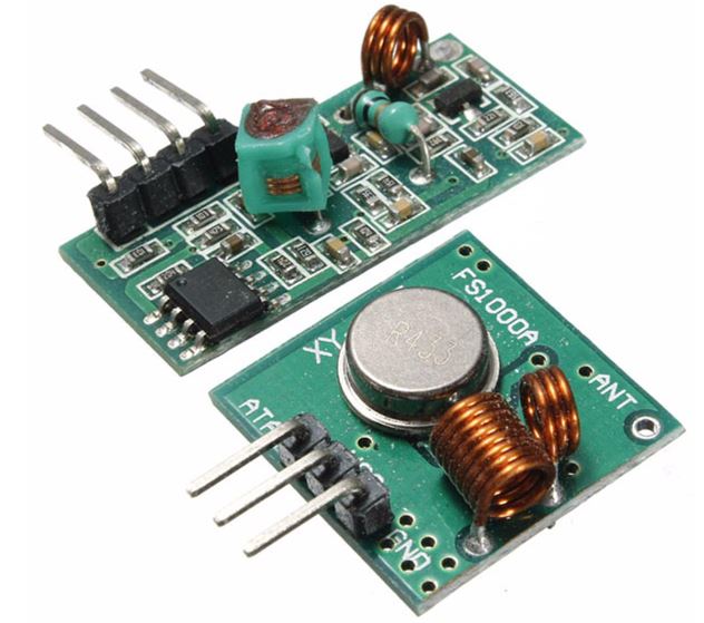
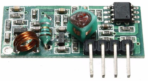
The 433 MHz Transmitter and Receiver Modules
433 MHz RF Transmitter and Receiver Module
These modules are very popular among makers and DIY enthusiasts due to their low cost and ease of use. They are used in all forms of short-range, simplex-based communication between two microcontrollers with one of the microcontroller serving as the transmitter while the other serves as the receiver. These modules are ASK (Amplitude Shift Keying) or OOK (Of Hook Keying) type RF modules, that means they usually draw no power when transmitting a Logic “zero” and as such consumes a significantly low amount of power. This low power consumption makes them very useful in battery-based implementations.
Some of the specifications of the transmitter and receiver modules are listed below.
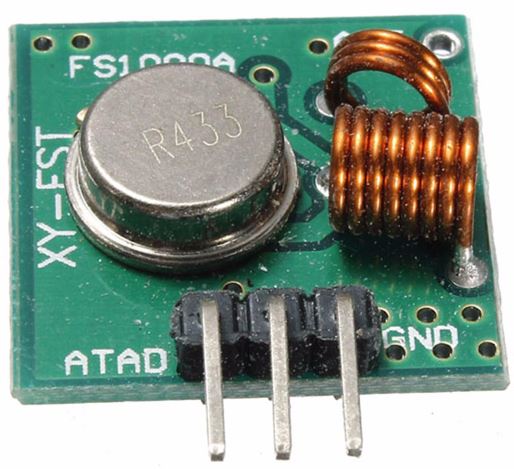
Transmitter Specifications
433 MHz RF transmitter
Working voltage: 3V – 12V
Working current: max Less than 40mA max, and min 9mA
Resonance mode: (SAW)
Modulation mode: ASK
Working frequency: 433.92MHz
Transmission power: 25mW
Frequency error: +150kHz (max)
Velocity: less than 10Kbps
Transmission range: 90m (in open space)
Receiver Specifications
433MHz Receiver Module
Working voltage: 5.0VDC +0.5V
Working current:≤5.5mA max
Modulation mode: OOK/ASK
Working frequency: 433.92MHz
Bandwidth: 2MHz
Sensitivity: exceeds –100dBm (50Ω)
To demonstrate the ease with which wireless capabilities can be added to projects using these modules, we will build a weather station with remote data display. The weather station will comprise primarily of a temperature and humidity sensor and the 433 RF transmitter module. It will measure the temperature and humidity of the environment and send it via the RF transmitter to the display unit (received via the RF receiver module) on a ST7735 1.8″ Color TFT LCD display.
Required Components
The following components are required to build this project:
As usual, all of these components can be bought via the links attached above.
Schematics
There are two schematics for this project. The first one is for the transmitter which obtains temperature and humidity from the environment and sends it to the second half of the project, the receiver, which displays the data on the display.
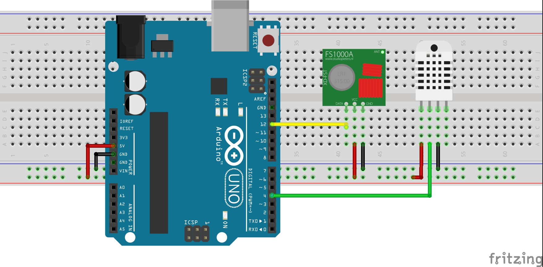
Schematic for the Transmitter
The transmitter circuit comprises of an Arduino, the DHT22 temperature and humidity sensor, and the 433 MHz RFtransmitter module. A battery pack can be added to provide power to the Arduino when its disconnected from the computer. Connect the components as shown below.
Transmitter Schematics
For clarity, the pin connections between the Arduino and the other components are displayed below.
Arduino – 433 MHz Tx Module
5V - VCC
12 - Data
GND - GND
Arduino – DHT22
5V - VCC
D4 - Signal
GND - GND
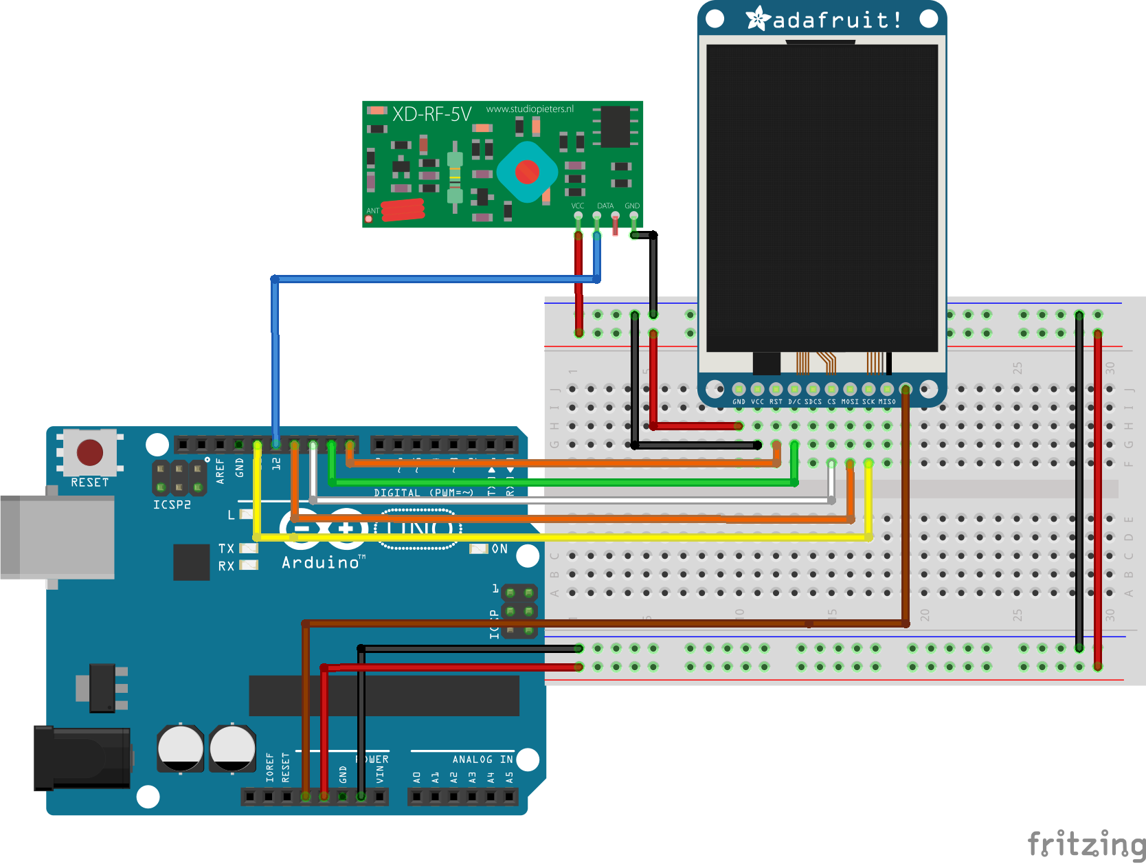
Schematics for the Receiver Circuit
The receiver is made up of the 433 MHz RF receiver module, the ST7735 1.8″ Color TFT Display, and an Arduino Uno. Connect the components as shown below.
Schematics for Receiver
Due to a variation in pinout of the display from one manufacturer to another and for clarity, the pin connection between the Arduino and the other components that make up the receiver are mapped out below:
To better understand the use of the ST7735 1.8″ Color display with the Arduino, check out one of our previous tutorial on connecting the display to the Arduino.
With the connections all done, we can now proceed to write the code for this project.
Code
Just like we had to build two devices, we will write two different codes for this project. One of the codes is to control the transmitter and the other to control the receiver.
To easily write the code for this tutorial, we will use the libraries that make it easy to drive each part of the project. For the RF modules, we will use the virtual wire library, to send and receive data, while for the display of the received data, we will use the Adafruit GFX and the Adafruit ST7735 libraries to easily update the ST7735 LCD display. To cap it, we will use the Adafruit DHT sensor library to easily obtain temperature and humidity data from the DHT22 sensor.
The algorithm behind the code is simple. For the transmitter, obtain the temperature and humidity values from the DHT22 and send via the RF transmitter to the receiver. For the receiver, obtain the temperature and humidity value sent by the transmitter using the RF Receiver module and display on the LCD.
As usual, I will do a brief explanation of the code for the two halves of the project starting with that of the transmitter.
Transmitter code
We start by including the libraries that will be used within the code.
//Written by Nick Koumaris
//info@educ8s.tv

#include <VirtualWire.h>
#include "DHT.h"
After this, we declare the pin of the Arduino to which our DHT is connected and also specify the type of DHT being used.
#define DHTPIN 4

#define DHTTYPE DHT22
Next, we indicate the pin of the Arduino which will be used as our data transmission pin (which is connected to the data pin of the RF transmitter module) and create a struct package which will be used for sending the data.
const int led_pin = 13;
const int transmit_pin = 12;

struct package
{
  float temperature ;
  float humidity ;
};
Next, we define the type for the package and create an instance of the DHT class to address the DHT sensor.
With this done, we move to the void setup() function where we set the TX pin and other parameters to initialize the RF module.
void setup()
{
// Initialise the IO and ISR
vw_set_tx_pin(transmit_pin);
vw_set_ptt_inverted(true); // Required for DR3100
vw_setup(500); // Bits per sec
pinMode(led_pin, OUTPUT);
}
Up next is the void loop() function where we obtain the temperature and humidity using the read sensor function. After obtaining the data, it is sent using the vw_send() function. A 2000ms delay time is implemented to create an interval between the data and ensure one is sent before the other.
void loop()
{
digitalWrite(led_pin, HIGH); // Flash a light to show transmitting
readSensor();
vw_send((uint8_t *)&data, sizeof(data));
vw_wait_tx(); // Wait until the whole message is gone
digitalWrite(led_pin, LOW);
delay(2000);
}
The complete code is written below and attached to the zip file under the download section.
#include <VirtualWire.h>
#include "DHT.h"
#define DHTPIN 4
#define DHTTYPE DHT22
const int led_pin = 13;
const int transmit_pin = 12;
struct package
{
float temperature ;
float humidity ;
};
typedef struct package Package;
Package data;

DHT dht(DHTPIN, DHTTYPE);
void setup()
{
    // Initialise the IO and ISR
    vw_set_tx_pin(transmit_pin);
    vw_set_ptt_inverted(true); // Required for DR3100
    vw_setup(500);       // Bits per sec
    pinMode(led_pin, OUTPUT);
}
void loop()
{
  digitalWrite(led_pin, HIGH); // Flash a light to show transmitting
  readSensor();
  vw_send((uint8_t *)&data, sizeof(data));
  vw_wait_tx(); // Wait until the whole message is gone
  digitalWrite(led_pin, LOW);
  delay(2000);
}
void readSensor()
{
dht.begin();
delay(1000);
data.humidity = dht.readHumidity();
data.temperature = dht.readTemperature();
}
Receiver Code
As usual, we start by including the libraries that will be used.
//Written by Nick Koumaris
//info@educ8s.tv

#include <VirtualWire.h>
#include <Adafruit_ST7735.h>
#include <Adafruit_GFX.h>
Next, we declare the pins of the Arduino to which the pins of the LCD are connected.
#define TFT_CS     10
#define TFT_RST    8
#define TFT_DC     9
Adafruit_ST7735 tft = Adafruit_ST7735(TFT_CS,  TFT_DC, TFT_RST);

// Option 2: use any pins but a little slower
#define TFT_SCLK 13   // set these to be whatever pins you like!
#define TFT_MOSI 11   // set these to be whatever pins you like!
Next, we declare the pin(receive_pin) of the Arduino to which the data pin of the RF receiver module is connected and create char variables to hold the temperature and humidity values.
const int receive_pin = 12;
char temperatureChar[10];
char humidityChar[10];
Next, we create a struct package similar to the one within the transmitter code.
With this done, we move to the void setup() function where we initialize the display and the RF receiver module setting the bit rate and starting the receiver PLL.
void setup()
{
tft.initR(INITR_BLACKTAB);
tft.fillScreen(ST7735_BLACK);
printUI();
delay(1000);
// Initialise the IO and ISR
vw_set_rx_pin(receive_pin);
vw_setup(500); // Bits per sec
vw_rx_start(); // Start the receiver PLL running
}
Next, the void loop() function. We start the function by checking if a message has been received using the vw_have_message() function. If a message was received, we extract the temperature and humidity data from it and display it on the LCD.
void loop()
{
uint8_t buf[sizeof(data)];
uint8_t buflen = sizeof(data);
if (vw_have_message()) // Is there a packet for us?
{
vw_get_message(buf, &buflen);
memcpy(&data,&buf,buflen);
Serial.print("\nPackage:");
Serial.print(data.temperature);
String temperatureString = String(data.temperature,1);
temperatureString.toCharArray(temperatureChar,10);
tft.fillRect(10,20,80,30,ST7735_BLACK);
printText(temperatureChar, ST7735_WHITE,10,20,3);
String humidityString = String(data.humidity,1);
humidityString.toCharArray(humidityChar,10);
tft.fillRect(10,95,80,100,ST7735_BLACK);
printText(humidityChar, ST7735_WHITE,10,95,3);
Serial.print("\n");
Serial.println(data.humidity);
}
}
The code also includes functions which were used to display the results in a more user-friendly way.
void printText(char *text, uint16_t color, int x, int y,int textSize)
{
tft.setCursor(x, y);
tft.setTextColor(color);
tft.setTextSize(textSize);
tft.setTextWrap(true);
tft.print(text);
}
void printUI()
{
printText("TEMPERATURE", ST7735_GREEN,30,5,1); // Temperature Static Text
printText("o", ST7735_WHITE,90,13,2);
printText("C", ST7735_WHITE,105,20,3);
printText("HUMIDITY", ST7735_BLUE,30,80,1); // Temperature Static Text
printText("%", ST7735_WHITE,90,95,3);
}
The complete code for the receiver is available below. It is also attached in the zip file under the download section of this tutorial.
#include <VirtualWire.h>
#include <Adafruit_ST7735.h>
#include <Adafruit_GFX.h>
#define TFT_CS 10
#define TFT_RST 8
#define TFT_DC 9
Adafruit_ST7735 tft = Adafruit_ST7735(TFT_CS, TFT_DC, TFT_RST);
// Option 2: use any pins but a little slower!
#define TFT_SCLK 13 // set these to be whatever pins you like!
#define TFT_MOSI 11 // set these to be whatever pins you like!
const int receive_pin = 12;
char temperatureChar[10];
char humidityChar[10];
struct package
{
  float temperature = 0.0;
  float humidity = 0.0;
};
typedef struct package Package;
Package data;
void setup()
{
    tft.initR(INITR_BLACKTAB);
    tft.fillScreen(ST7735_BLACK);
    printUI();
    delay(1000);

    // Initialise the IO and ISR
    vw_set_rx_pin(receive_pin);
    vw_setup(500);	 // Bits per sec
    vw_rx_start();       // Start the receiver PLL running
}
void loop()
{
    uint8_t buf[sizeof(data)];
    uint8_t buflen = sizeof(data);

if (vw_have_message())  // Is there a packet for us?
  {
    vw_get_message(buf, &buflen);
    memcpy(&data,&buf,buflen);

    Serial.print("\nPackage:");
    Serial.print(data.temperature);
    String temperatureString = String(data.temperature,1);
    temperatureString.toCharArray(temperatureChar,10);
    tft.fillRect(10,20,80,30,ST7735_BLACK);
    printText(temperatureChar, ST7735_WHITE,10,20,3);

    String humidityString = String(data.humidity,1);
    humidityString.toCharArray(humidityChar,10);
    tft.fillRect(10,95,80,100,ST7735_BLACK);
    printText(humidityChar, ST7735_WHITE,10,95,3);

    Serial.print("\n");
    Serial.println(data.humidity);
  }
}
void printText(char *text, uint16_t color, int x, int y,int textSize)
{
  tft.setCursor(x, y);
  tft.setTextColor(color);
  tft.setTextSize(textSize);
  tft.setTextWrap(true);
  tft.print(text);
}

void printUI()
{
    printText("TEMPERATURE", ST7735_GREEN,30,5,1);  // Temperature Static Text
    printText("o", ST7735_WHITE,90,13,2);
    printText("C", ST7735_WHITE,105,20,3);

    printText("HUMIDITY", ST7735_BLUE,30,80,1);  // Temperature Static Text
    printText("%", ST7735_WHITE,90,95,3);
}
Demo
Upload the corresponding code to each of the Arduinos. Both Arduino boards can be powered using a battery pack. Few minutes after switching the devices on, you should see the temperature and humidity data, displayed on the LCD.
The range of the 433 MHz Transmitter and receiver module pair is generally small but by soldering external antennas, their range could be increased.
That’s it for this tutorial guys, did you make anything based on this project, or you made modifications to get better range for your modules, feel free to drop a comment.
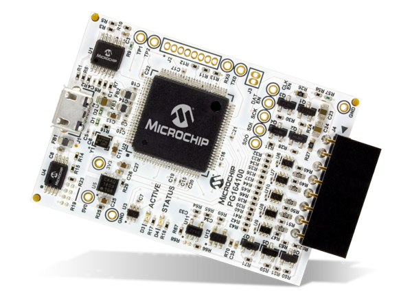
RS Components is now stocking Microchip’s MPLAB Snap in-circuit debugger/programmer, for simple and quick debugging and programming of most Microchip PIC, AVR and SAM flash MCUs. [via]
The MPLAB® Snap In-Circuit Debugger/Programmer allows affordable, fast and easy debugging and programming of most PIC®, dsPIC® and AVR flash MCUs, using the powerful graphical user interface of MPLAB X Integrated Development Environment (IDE) version 5.05 or later.
Connects to computer via high speed USB 2.0(480) cable An 8- pin SIL programming connector and the option to use various interfaces program devices using MPLAB X IDE or MPLAB IPE
The MCUs programmable by the MPLAB Snap include 32-bit devices and dsPIC digital signal controllers (DSCs). MPLAB Snap is ideal for projects that do not require high-voltage programming or advanced debugging. The debugger/programmer offers all the entry-level features that are required to debug prototypes quickly.
MPLAB Snap uses the GUI of the MPLAB X IDE, version 5.05 or later. It uses a 480 Mbps USB 2.0 interface to connect to the computer and an 8-pin single in-line (SIL) connector to connect to the target. Two device I/O pins and the reset line are used to implement in-circuit debugging and Microchip ICSP (in-circuit serial programming). MPLAB Snap’s onboard 32-bit 300 MHz SAM E70 MCU, based on an Arm Cortex-M7 core, matches the clocking speed of the target device.

 The board in on sale for 16.90 USD, found on seeedstudio.com