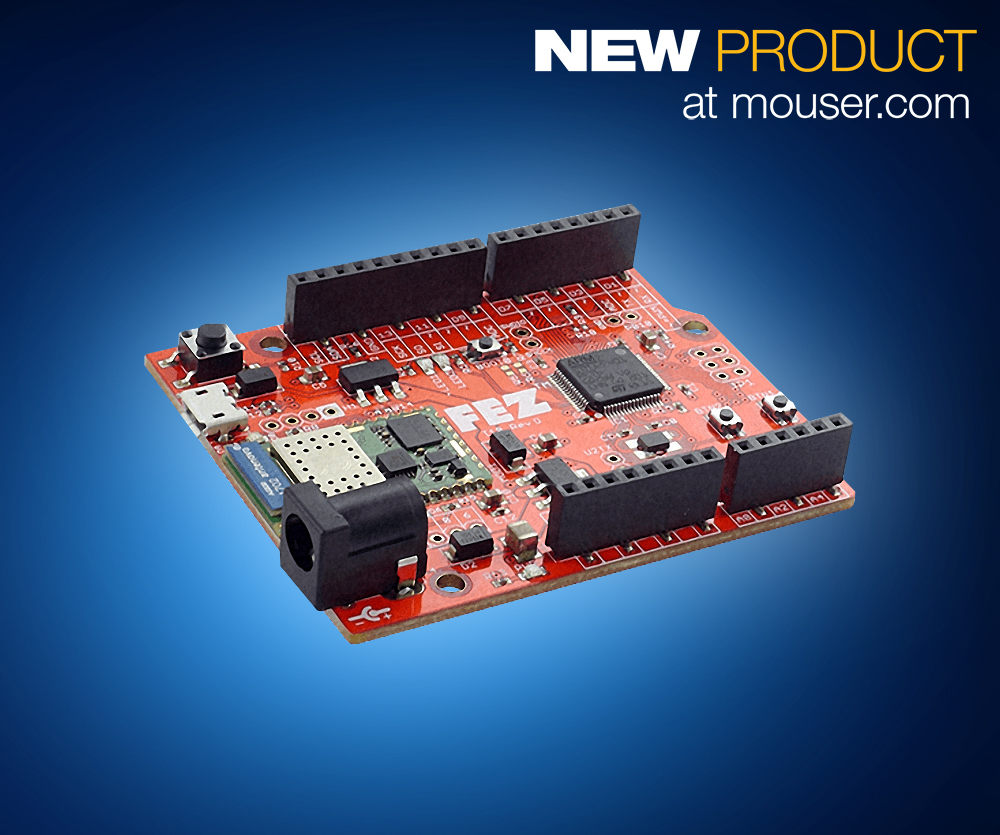
Available with multiple software support options, GHI Electronics offers FEZ t18 maker boards. Mouser Electronics is the first distributor to stock the latest boards in the FEZ series.
The advanced and user-friendly boards are pinout-compatible with Arduino Uno boards and shields and can be programmed using multiple programming languages and development environments.
The GHI Electronics FEZ maker boards incorporate a 32-bit STMicroelectronics STM32F4 Arm Cortex-M4 microcontroller with 512-kbytes of flash and 96-kbytes of SRAM. The STM32F4 chip is supported by a variety of common platforms, including Arduino, Arm mbed, MicroPython, Keil, GCC, and FreeRTOS, as well as GHI’s TinyCLR operating system (OS).
The TinyCLR OS enables managed .NET development and debugging using Visual Studio with support for programming in .NET, C# and Visual Basic over a USB cable with no additional hardware required. TinyCLR OS also includes the necessary drivers to make secure Wi-Fi connections available through a .NET-compatible interface.
The FEZ boards are available with an optional onboard Wi-Fi module that includes a secure networking feature set for the Internet of Things (IoT).
Time is a critical element of our existence that will never get old, and with technology, we can find better and more intuitive ways to measure it. In one of our past tutorials, we looked at how the DS3231 real time clock module can be used with Arduino to display time on a 16×2 LCD display. Today, we will build an upgrade to that project using an Arduino Due, the DS3231 RTC module and a 3.2″colour TFT display in place of the 16×2 LCD display used in the previous project.
Real Time Clock Update
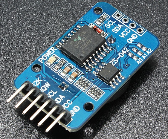
At the heart of today’s project is the DS3231 real time clock module which we will use to obtain the current time, date and temperature of the environment. The DS3231 real time clock module is one of the most popular real-time clock chips among makers and DIY enthusiasts. It is a low-cost, highly accurate, I2C based real-time clock (RTC) with a temperature-compensated crystal oscillator (TCXO) and crystal integrated into it. The module integrates a coin cell battery input which helps it retain date and time even when the main power to the device is interrupted. It maintains seconds, minutes, hours, day, date, month, and year information, automatically adjusting the date for months with fewer than 31 days, including corrections for leap year. It can be set to operate either in the 24-hour or 12-hour format with an active-low AM/PM indicator. It has been used in several projects on this website mostly, due to its accuracy, and its low power requirements which help it keep time accurately, for a longer period of time compared to other real-time clocks (RTC) modules.
DS3231 RTC Module
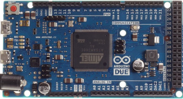
Another key part/component that we will use in today’s tutorial is the Arduino Due. One of the important things, when designing electronic systems that have displays is ensuring, that there is no flicker or lag when updating information on the screen and one of the best ways to ensure that, is to use a fast enough micro-controller. Putting this into consideration, for this project, we will use the very fast Arduino Due board. The Arduino Due has one of the fastest CPU in the Arduino family. The Due runs on an 84MHz CPU compared to the 16MHz CPU speed of the Arduino UNO, and as such, it is able to update the screen without any visible flickering.
Arduino Due
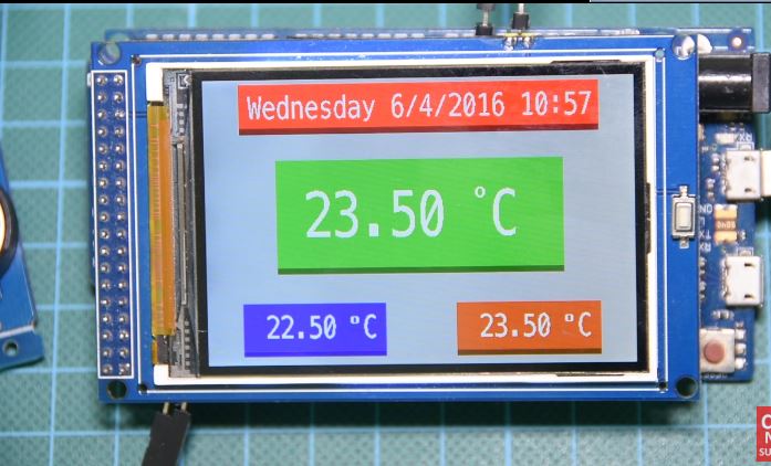
The most important update to the previous project, however, is the 3.2″color LCD display being used. The display gives us the ability to create a better, bigger and colourful user interface for our clock at a cheap price as it costs about 7$ on banggood.
The goal for this project is to build a real-time clock with a user-friendly interface capable of displaying (without lag or flickering) the current time, date, temperature including the minimum and maximum temperature recorded in a particular environment over time.
Required Components
The following components are required to build this project;
As usual, all of these components can be bought via the links attached to them.
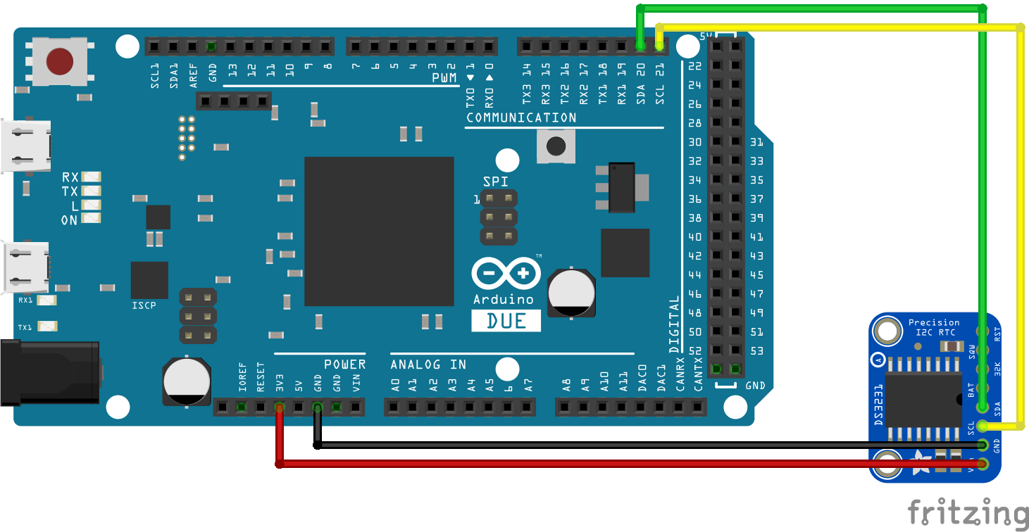
Schematics
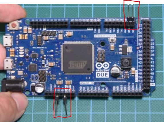
The 3.2″ TFT, like most other TFT displays, comes as a shield which can be easily mounted on the Arduino Due. This, however, makes it difficult to access the IOs of the Arduino after the display has been mounted, as it tends to cover the front face of the board. To solve this, so that the DS3231 module can be connected, male headers are used (after bending them as shown in the picture below) to connect the RTC module to the Arduino.
Pin Modification
Connect the DS3231 to the Arduino as shown below.
Schematics
The DS3231 module is an I2C based device, and it’s thus connected to the Arduino as shown above. For clarity a pin map is made available below;
With the connections all done, we can move to the code for the project.
Code
To easily write the code for this project, we will use two libraries: the Bodmer TFT HX8537 library for the TFT display and the Sodaq DS3231 library to easily interface with the DS3231 module. Both libraries can be downloaded via the links attached to their names above. The Bodmer library is a version of the UTFT library specially modified for the Arduino Due as this particular display is incompatible with the UTFT library.
With the libraries installed, relaunch the IDE to begin writing the code. The code for this project is quite simple but bulky, due to the functions used to create the user interface.
As usual, we start the code by including the libraries needed for the project.
// Written by Nick koumaris
// info@educ8s.tv
#include <TFT_HX8357_Due.h> // https://github.com/Bodmer/TFT_HX8357_Due
#include <Sodaq_DS3231.h>  //RTC Library https://github.com/SodaqMoja/Sodaq_DS3231
Next, we create variables that will be used to store information in our code. With this done, we create an instance of the HX8357 library.
Next is the void setup function. We initiate communication with the RTC module and Initialize the display, setting our preferred orientation for the display and print the UI to the display.
With this done, we move to the void loop function. Under this function, we write the code to update all the parameters (after specific intervals) on the display including the min temperature, the max temperature, time and the date.
The other part of the code are functions used for creating the User Interface for the screen.
The complete code for the project is attached under the download section below.
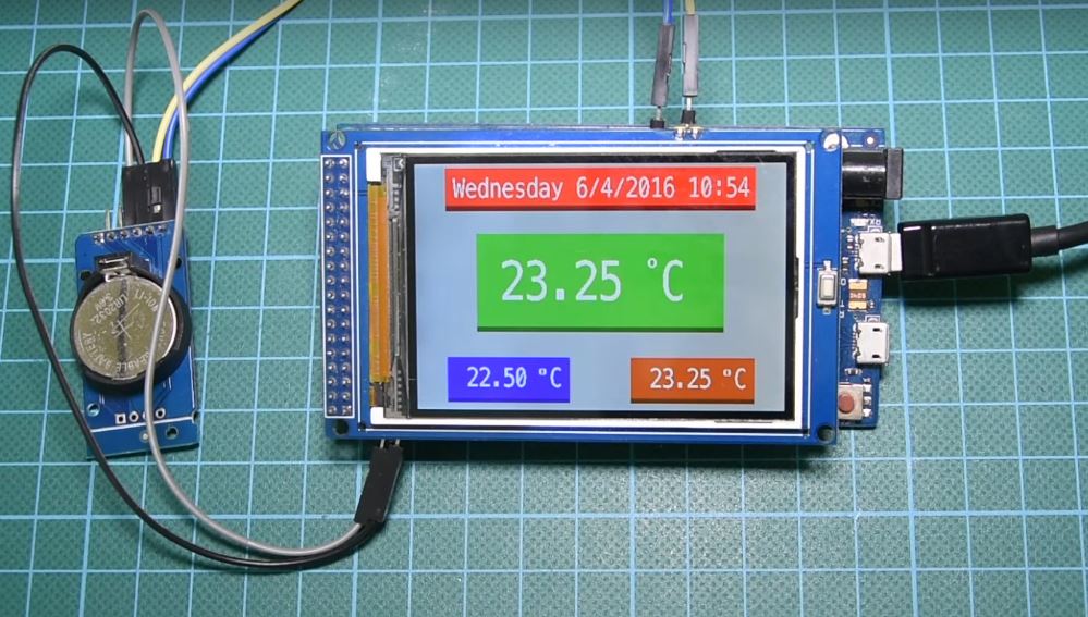
Demo
Upload the code to Arduino, and you should see the screen come up with the time and temperature as shown in the image below.
Demo
That’s it for this tutorial guys, there are several useful projects that can be built using this tutorial as a foundation. You could decide to add a buzzer to the project to create an alarm clock or make a to-do list based project, all out of this.
Till next time!
The video version of the tutorial is available on youtube here.
VIA Technologies has unveiled a mini-PC that runs Android 8.0 on a Snapdragon 820E named the VIA ALTA DS 3 Edge AI. The VIA ALTA DS 3 Edge AI operates an Android 8.0 “Oreo” BSP for the Snapdragon 820E, which also powers the Arrow/Qualcomm DragonBoard 820c SBC. The Snapdragon 820E is a close replica, variant of the Snapdragon 820, in league with other embedded Snapdragon variants with 10 years lifespan such as the Snapdragon 600E.
VIA ALTA DS 3 Edge AI System
Like the 820, it has four Kryo cores two at 2.35GHz, and two at 1.6GHz plus a 624MHz Adreno 530 GPU, a Hexagon 680 DSP, and a 14-bit Spectra ISP. the Alta DS 3 uses Qualcomm’s Neural Processing SDK for operating various neural network models trained in Caffe/Caffe2, ONNX, or TensorFlow using the CPU, GPU or DSP,” according to VIA.
The VIA ALTA DS 3 provides tightly-integrated system platform that accelerates innovation at the edge for multimedia-rich New Retail applications that boost customer convenience and engagement
says Richard Brown, Vice-President of International Marketing, VIA Technologies, Inc. This includes applications that combine AI algorithms with “immersive multimedia signage display content.”
Other applications to benefit from this operating system include “facial recognition check-in systems for hotels, train stations, airports, and payment authentication systems for cashierless stores, vending machines, and ticket kiosks.
The mini PC which is 175 x 118 x 25mm in size is equipped with 4GB LPDDR4 in a POP package, as well as 16GB eMMC and an SD slot. There’s also an M.2 slot for 2280 NVMe SSDs. The ALTA DS 3 also has a GbE port, a mini-USB port with “fastboot mode only”, and 3x USB 3.0 ports. Dual 4K display including dual display mirrors and independent video playback are available via the dual HDMI ports, which are described as offering an “integrated HDMI 2.0 transmitter and dual DSI to HDMI 1.4 converters.”
VIA ALTA DS 3 Edge AI System with antenna mount
The system comes with a USB-only miniPCIe slot, a SIM card slot, and an antenna mount. Dual audio jacks (WCD9335 codec), a 12V DC jack, a power button with LED, a TPM 1.2 security chip, and a Kensington lock are also available. The 0.61 kg system can be used in temperatures between 0 to 40°C and comes with a vertical stand holder and optional VESA. The VIA ALTA DS 3 is now on sale worldwide. System samples can be ordered online for US$399 plus shipping.
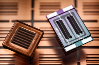
A new innovative technology for wearables is taking over the market of future technology. Wearables are portable systems that house sensors to make measurements from the wearer’s body. Powering these wearables requires flexible batteries that adapt to the specific material, and deliver the power needed for the system.
Fraunhofer Institute for Reliability and Microintegration IZM developed a micro battery to address this new technology trend. Wearables are used in medical practices to collect data, like recording long-term ECGs without interfering with the patient day to day activities. It is also a convenient way of monitoring a patient’s heartbeat since the sensors are light, flexible and concealed in clothing. This technology could also be applied to accessories like fitness bands that measure jogger’s pulse while running.
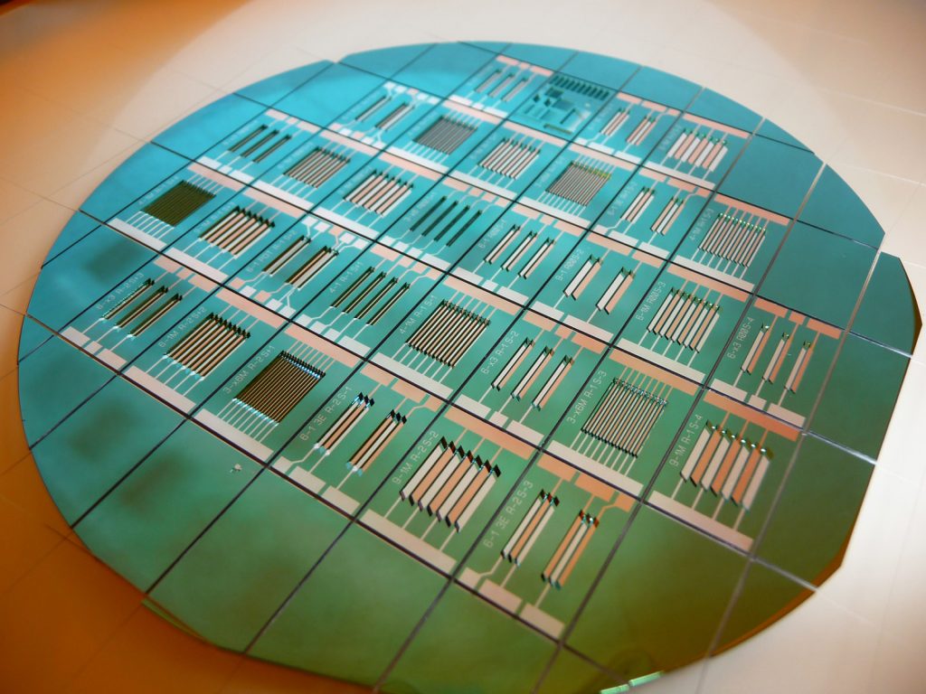
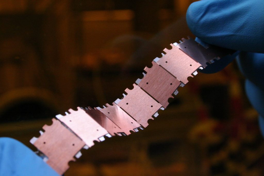
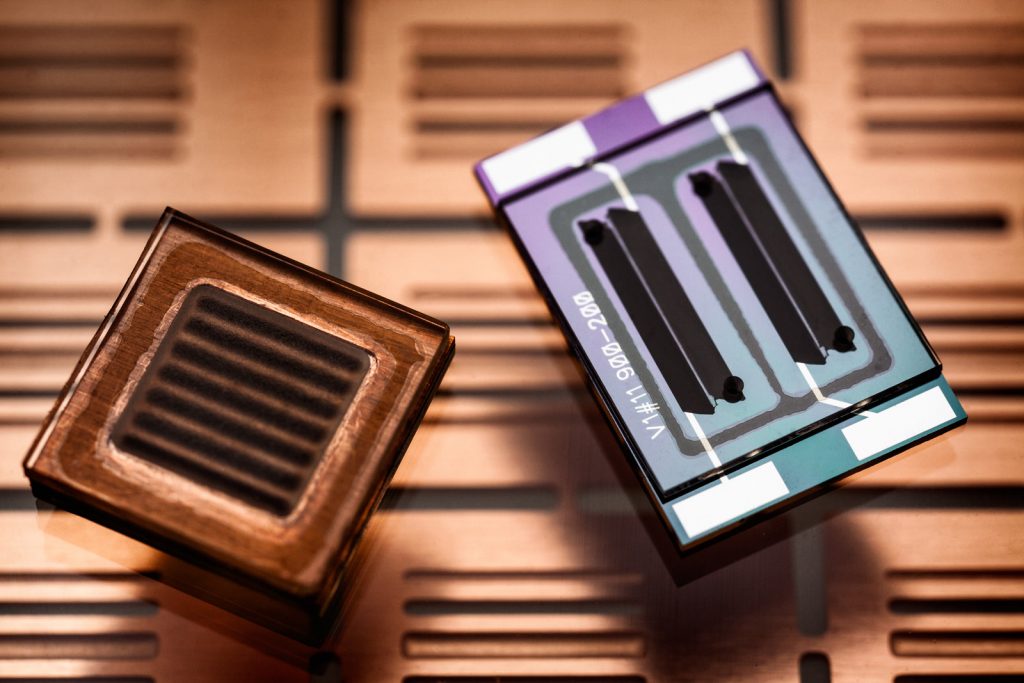
Technical concerns about this technology include durability, energy density and material requirements and parameters such as weight, flexibility and size must be considered. Fraunhofer IZM developed a prototype wristband that combines all this. The key to this is its three gleaming green batteries. The 300 milliampere batteries supply the wristband with power.
The batteries can store energy up to 1.1 Wh and loose less than 3% of their charge capacity per year. This features make the new prototype superior to smart bands available in the market, it also creates the avenue for other portable electronics to be supplied with energy from these batteries.
This technology is successful due to the segmented approach. Instead of making the batteries extremely flexible at the cost of energy density and reliability, the institute directed its focus to designing very small and powerful batteries for optimized mounting. The batteries are malleable in between segments.
The smart band is flexible and produce more power compared to other smart wristbands available on the market. Fraunhofer IZM also uses customer tailored solutions to develop batteries for wearables. They consult with customers to draw up energy requirements. They consider shape, size, voltage, capacity and power to create a power supply concept.
Also, a wearable plaster technology has gone into development. This is in conjunction with Swiss sensor manufacturer Xsensio. This project aims to develop a plaster that can directly measure and analyze a patient’s sweat. The result from the plaster can then be used to draw conclusions about the patient’s general state of health. Fraunhofer IZM has taken the responsibility of developing the design concept and energy supply system for the sweat measurement sensors.
They plan is to integrate sensors that are extremely flat, light and flexible. One way would be an encapsulation system made out of aluminium composite foil. They also have to use materials that are inexpensive and easy to dispose of.
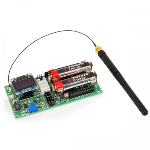
Antennino (the name Antennino is the combination of Antenna and Arduino) is a low-cost and low-power board based on the Atmel chip, then 100% compatible with the traditional Arduino IDE. The board integrates sensors and bus communication to get external information, as well as a wireless link to communicate with the outside. <span title=”A seconda di come viene equipaggiata, può funzionare sia da modulo remoto che da collettore di informazioni (gateway).
“>Depending on how it is equipped, it can work both from a remote module and from an information collector (gateway).
The heart of Antennino is an ATmega328P microcontroller (the P indicates that it is a chip that adopts the PicoPower technology, essential for the energy management desired in the project). Communication with the outside world takes place via a transceiver module RFM69 (www.hoperf.com) transceiver that operates in the 433 MHz frequency band and supports AES encryption at the hardware level.
On board the Antennino a Flash memory (AT25F512B – 512 Kbit) has been prepared that can be used to store data related to the reading of the sensors (Data Logger) or to implement the Wireless programming (OTA) of the antennino module, a sensor temperature (DS18B20) and a photoresistor.
Features:
ATmega328P processor
433 MHz RFM69 Transceiver Module
Flash memory AT25F512B – 512-Kbit
Supply:
– using two standard 1.5V alkaline AA batteries or 1.2V rechargeable batteries (the battery clips are already present on the PCB)
– by an external voltage of 3.6 ÷ 12 V
– directly with a voltage of 3.3V, bypassing all the regulators present on board the board
In the latter event, remember not to exceed the voltage of 3.3V, otherwise you will damage the microcontroller and the various chips connected to it.
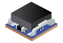
The TPSM84824 power module is an easy-to-use integrated power supply that combines an 8-A DC/DC converter with power MOSFETs, a shielded inductor and passives into a small form-factor QFM package. This power solution allows as few as six external components while maintaining the ability to adjust key parameters to meet specific design requirements. Ultra-fast transient response can be achieved by use of the TurboTrans™ feature. TurboTrans allows the transient response to be optimized for reduced output voltage deviation with less required output capacitance.
The 7.5 mm × 7.5 mm × 5.3 mm, 24-pin QFM package is easy to solder to a printed circuit board and has excellent power dissipation capability. The TPSM84824 offers flexibilty with many features including power good, programmable UVLO, tracking, prebias start-up, as well as overcurrent and overtemperature protection making it a great product for powering a wide range of devices and systems.
Features
Integrated Inductor Power Solution
7.5 mm × 7.5 mm × 5.3 mm QFM Package
All Pins Accessible From Package Perimeter
Input Voltage Range: 4.5 V to 17 V
Wide-Output Voltage Range: 0.6 V to 10 V
Efficiencies up to 96%
Adjustable Fixed Switching Frequency
(200 kHz to 1.6 MHz)
TPSM84824 – 4.5V to 17V Input, 0.6V-10V Output, 8A Power Module – [Link]
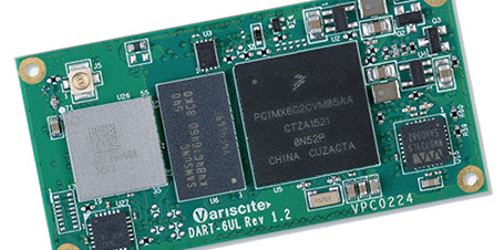
Variscite is releasing another pin-compatible version of their 50 x 25mm DART-6UL computer-on-module. This time it will be loaded with NXP’s headless new i.MX6 ULZ variant of the single Cortex-A7 core i.MX6 UL. This yet unnamed module lacks display or LAN support. It is described as “a native solution for headless Linux-based embedded products such as IoT devices and smart home sensors requiring low power, low size, and rich connectivity options.”
The lack of display and LAN features mimic the limitations of the cost-effective Linux processor i.MX6 ULZ by NXP. The headless, up to 900MHz Cortex-A7 ULZ SoC offers most of the I/O of the of the i.MX6 UL/ULL, including ESAI, S/PDIF, and 3x I2S audio interfaces, but features such as the 2D Pixel acceleration engine and Ethernet controllers are missing.
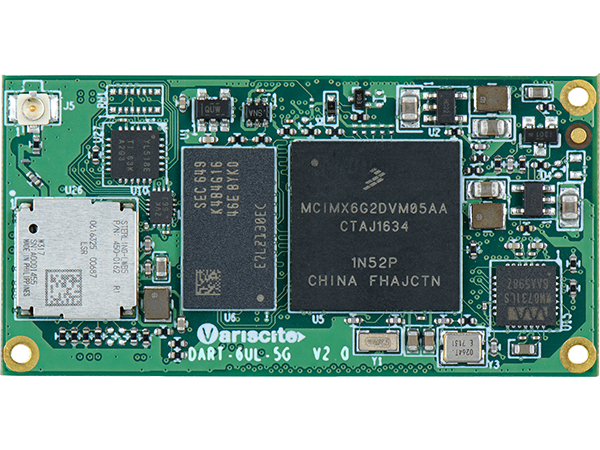
We’ve seen last year, Variscite upgraded the Linux-ready DART-6UL into a faster, 696MHz v1.2, which added the option of NXP’s power-efficient i.MX6 ULL SoC in addition to the i.MX6 UL. It was followed up with a DART-6UL-5G model that houses an onboard, certified WiFi/Bluetooth module with dual-band, 2.4GHz/5GHz 802.11ac/a/b/g/n.
The upcoming i.MX6 ULZ based version has the same WiFi-ac module with Bluetooth 4.2 BLE. Like the latest versions of the other DART-6UL modules, the module can be clocked to 900MHz. The “cost effective” ULZ version only lacks the touch-enabled, 24-bit parallel RGB interface and dual 10/100 Ethernet controllers. Other deducted features compared to earlier models include dual CAN, parallel camera, and “extra security features.”
The new module is also limited to a temperature range of 0 to 85°C instead of being available in 0 to 70°C or -40 to 85°C versions. The i.MX6 ULZ SoC itself has a slightly wider range of 0 to 95°C. The pin-compatible DART-6UL with iMX6 ULZ will offer the i.MX6 ULZ SoC with optional security features. It will include TRNG, AES crypto engine, and secure boot. This 50 x 25mm module will ship with 512MB DDR3L. The storage range is similar, with a 512MB NAND and up to 64GB eMMC.
The DART-6UL with i.MX6 ULZ will support 2x USB 2.0 OTG host/device ports, audio in and out, and UART, I2C, SPI, PWM, and ADC interfaces. OS support is revealed as Linux Yocto, Linux Debian, and Boot2QT.
The DART-6UL with iMX6 ULZ will be available in the fourth quarter this year. The DART-6UL/ULL/ULZ product page mentions that the lowest, volume-discounted price is $24. More information may be found in Variscite’s announcement.
Microchip has launched MPLAB X IDE version 5.05 which beta supports the majority of AVR MCUs – allowing developers to easily incorporate AVR MCUs into any application. [via]
Further support for additional AVR MCUs will be provided in MPLAB versions. AVR support will continue to be added to Atmel Studio 7 and Atmel START for current and future AVR devices.
MPLAB X IDE version 5.05 provides a unified development experience that is both cross-platform and scalable with compatibility on Windows, MacOS and Linux operating systems. The tool chain now supports MPLAB Code Configurator (MCC) code configuration tool, allowing developers to easily configure software components and device settings. MCC can also generate code for specific development boards, such as Microchip’s Curiosity ATMega4809 Nano (DM320115) development board and existing AVR Xplained development boards.
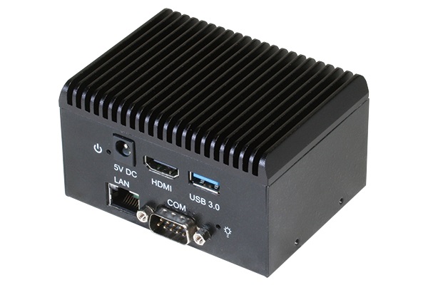
(Taipei, Taiwan – October 4, 2018) – AAEON, a leading developer of advanced IoT solutions, releases the UPC-GWS01, the world’s smallest x86-based industrial computer. Just 91mm x 67mm x 55.2mm in size, the system is highly versatile and boasts onboard storage, WiFi, Bluetooth, and a comprehensive I/O interface.
The UPC-GWS01, which has already won a Computex d&i Award, is built around AAEON’s state-of-the-art UP Core professional maker board. Featuring an Intel® Atom™ quad-core CPU, the SBC delivers low-power-consumption, high-performance specifications and is equipped with 2GB/4GB DDR3L memory and 16GB/32GB/64GB eMMC storage. The board is also fitted with USB3.0 and HDMI ports and has support for Windows 10, Windows 10 IoT Core, Linux, and Android 6.0.
Inside the chassis, the UP Core is paired with a carrier board that gives the system extra functionality. For the standard product, the carrier board adds a LAN port and COM port, but the UPC-GWS01 is more than just a general IPC solution. To maximize its potential as a flexible, large-scale maker platform, AAEON provides potential customers with design guidelines to help them design expansion boards and customized chassis to suit their applications.
With onboard WiFi and Bluetooth, a LAN port, and support for 3G/4G connectivity via an mPCIe slot, the UPC-GWS01 can serve as a flexible and incredibly portable IoT gateway device for smart home and smart retail systems. Its HDMI port and Intel Gen 8 HD 400 GPU, which enables 3D graphics, also make it ideal for digital signage applications.
“The UPC-GWS01’s tiny footprint, I/O interface, and onboard storage, WiFi and Bluetooth make this system the best on the market,” commented Irene Lin, AAEON design manufacturing service product manager. “The fact that AAEON has also released design guidelines to help you customize this maker platform means there’s no need to look anywhere else for a compact IoT Gateway.”
There are times you find yourself looking for a relatively high voltage (100V to 200V often in my case) but low current DC power supply. I have zener diodes that are higher than 30V, which makes the lab supply useless, and filament LEDs with forward voltage over 60V. When I need to test them quickly, I used to hook up a simple rectifier circuit to a variable AC power supply (nothing more than a slidac with isolation transformer). While this gets job done, the setup is capable of supplying much too high current (1A or more), so I was always very nervous and extra careful in handling the circuit. All I need is a little HV generator that gives me around 200V DC and only capable of supplying a milliamp or less. Realizing that I do have such design available – one of the Nixie supply circuit – I just decided to put one together to use.