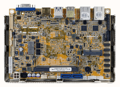
IEI is rejuvenating the G-Series with a 165 x 115mm EPIC form factor SBC named the Nano-GLX, which runs on the dual-core G-Series LX and has TDP ratings as low as 4.5W. This is the latest, and the most power efficient of the G-Series family. This is the pioneer G-Series based EPIC board. OS support is not listed, but possibly Linux and Windows can both run fine on it. The board is aimed at power efficient embedded applications (parking systems, industrial control, automation, and gaming systems).
Nano GLX SBC
The Nano-GLX supports the 1.8GHz G-Series GX-218GL and 1.5GHz GX-215GL, both with 15W TDPs, as well as the 1GHz GX-210KL with a 4.5W. Also supports up to 8GB DDR3/DDR3L RAM and offers dual, powered SATA III slots. Even though IEI mentions “dual PCIe Mini” in the ordering guide, the spec list shows that there is only a single mini-PCIe slot that supports both PCIe and mSATA.
The SBC is fitted with 2x GbE, 2x USB 3.0, and 2x USB 2.0 ports. Other posts included are VGA and 4K-ready HDMI port, which together enables dual autonomous displays. Also available is LVDS along with analog and S/PDIF audio interfaces. Onboard Input and output (I/O) includes 6x serial, 8-bit DIO, TPM, and more.
There are varieties of the board, which include a TPM 1.2 chip, various thermal solutions, and IEI’s iRIS-1010 module for out-of-band remote management. The 12V board has a 0 to 60°C operating range. The Processor has an AMD G-Series SoC LX (2x x86/Jaguar cores @ 1GHz to 1.8GHz); Radeon R1E GCU graphics; 1MB L2 cache; 4.5W to 15W TDP. It is fitted with a RAM capacity of up to 8GB DDR3-1600/1333 DDR3 or DDR3L via single SODIMM, 2x SATA 3.0 with 5V SATA power, mSATA via mini-PCIe slot.
Regarding networking, it is fitted with a 2x Gigabit Ethernet ports (Intel 1210-AT with NCIS and Intel 1211-AT). The media I/O components includes a dual autonomous displays, HDMI port (up to 3840 x 2160 @ 60Hz), VGA port (up to 2048 x 1536 @ 60Hz), 18/24-bit dual-channel LVDS (up to 1920 x 1200 @ 60Hz), Analog audio and S/PDIF (Realtek ALC892 HD Audio). Other I/O devices includes a 2x USB 2.0 headers, 5x RS-232 headers, RS-422/485 header, 8-bit DIO, KB/MS, SMBus, I2C, fan, and TPM headers.
For expansion, a full -size mini-PCIe slot (supports PCIe, SATA signal co-lay SATA port 2) is installed. It also features Watchdog; 3x LEDs; mounting holes for various thermal solutions; optional iRIS-1010 module; IEI One Key Recovery for rapid OS backup and recovery. It is equipped with a 12V DC input and power header (AT/ATX); power and reset buttons; [email protected] consumption with GX-210KL and 4MB.
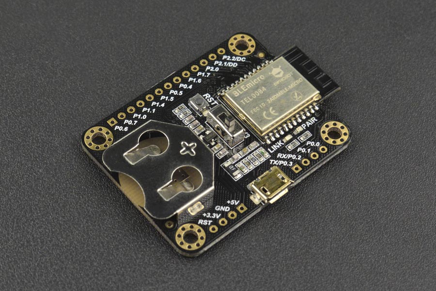
DFRobot Bluno is a Bluetooth 4.0 LE development board following Arduino UNO form factor, and powered by TI CC2540 chipset. The board sells for $24.90 on their online store, and the company provides firmware and mobile app source code, but if you ever wanted a similar solution in a much smaller form factor, and powered by a coin cell battery, the company has now launched BLE Micro board.
BLE Micro board specifications:
Bluetooth Chip – Texas Instruments CC2540 8051 MCU with USB, Bluetooth 4.0 LE connectivity
Wireless Connectivity
Frequency: 2.4GHz
Transfer rate: ≤1Mbps
Modulation: GFSK, Bluetooth low power, V4.0
Sensitivity: -93dB
Transmission distance – 30m in free space
USB – 1x micro USB port
Expansion – 21 through holes with reset, power signals, UART, and GPIOs.
Input Voltage: +3.3 DC
Power Consumption – Working: 10.6mA average, ready mode:8.7mA
Temperature Range – -10 ℃ ~ +65 ℃
Dimensions – 49mm x 35mm
You can find more details including schematics, AT command set, links and info for Android and iOS apps in the Wiki.
DFrobot’s BLE Micro board is sold for $19.90 in single quantity and a bit lower in higher quantities, e.g. $17 per unit for 10 pieces or more.
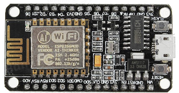
As the popularity of Arduino boards increased, the demand for boards which comes embedded with some of the add-ons used with the Arduino increased. One of the most popular add-ons were the WiFi modules which are used to connect Arduino boards to the internet. Several boards were released by different manufacturers which used the Arduino form factor and had onboard WiFi module, but none of these boards became as popular as the NodeMCU. Today, we will be exploring how to use the NodeMCU board in projects and especially how to easily program the board using the Arduino IDE.
The NodeMCU is an ESP8266 WiFi based microcontroller board that helped overcome some of the difficulties associated with several versions of boards based on the ESP8266 WiFi module/chips from Espressif.
Getting Started with the NodeMCU (ESP8266 Based Development Board) – [Link]
As the popularity of Arduino boards increased, the demand for boards which comes embedded with some of the add-ons used with the Arduino increased. One of the most popular add-ons were the WiFi modules which are used to connect Arduino boards to the internet. Several boards were released by different manufacturers which used the Arduino form factor and had onboard WiFi module, but none of these boards became as popular as the NodeMCU. Today, we will be exploring how to use the NodeMCU board in projects and especially how to easily program the board using the Arduino IDE.
The NodeMCU is an ESP8266 WiFi based microcontroller board that helped overcome some of the difficulties associated with several versions of boards based on the ESP8266 WiFi module/chips from Espressif.
NodeMCU
The Arduino came at a time when the IoT revolution was starting out and it gave makers the opportunity to be part of that revolution by building simple connected devices, combining the Arduino and several different kinds of WiFi and Ethernet modules/shields. All those modules were either too expensive or quite complex to use. So when the first version of the ESP8266 module (ESP-01) came to market, it was an absolute delight as the low price and quality drove the popularity of the chip. Users, however, quickly discovered several constraints from the power requirements to the breadboard unfriendliness of the chip. The chips had little (written in Chinese) or no documentation and this made them even more difficult to use. Several other versions of the modules were made but they all had similar constraints.
To resolve some of the issues associated with these modules, several breakout and development boards based on these modules were made such as the Wemos D1 (which worked like the Arduino Uno) and Wemos Mini boards, but none of them quite achieved the same level of popularity as the NodeMCU.
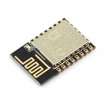
The NodeMCU board is essentially a breakout/development board for the ESP12E module by AI-thinker.
ESP-12E
The ESP-12E itself, just like the previous modules, was difficult to work with, due to factors including: breadboard unfriendliness, it requires header pins that were not common on the market, and the only solution to these problems, that was envisioned at the time, was an adapter coupled with an FTDI breakout board and some other connections to make it breadboard friendly and easy to program.
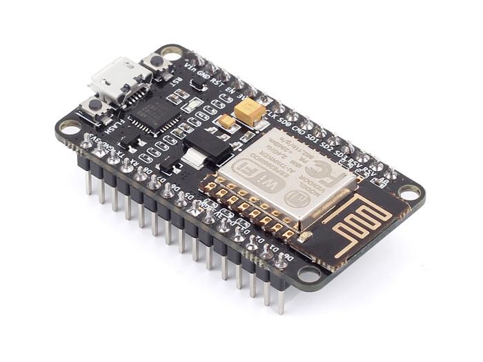
The NodeMCU was the product of that search, incorporating all the required components on a single breadboard friendly, ready to use board while retaining the low cost with which the ESP-based boards were associated.
Some of the features of the board include;
Arduino-like (software defined) GPIO
Can be programmed using the Esplorer IDE or the Arduino IDE.
Onboard USB-TTL converter for easy programming
10 onboard digital I/O pins, an analog pin along with pins for SPI, IIC, and 1-Wire communication protocols.
Extensive WiFi capabilities (Can create an access point and/or join an existing one). It is used to connect devices to the internet to fetch/ upload data and can serve as a mini webserver for simple pages.
Onboard PCB antenna.
3.3V logic level
Originally when the ESP8266 modules were released, to work in standalone mode, they had to be programmed using the ESplorer IDE which required a knowledge of the LUA programming language, but as things progressed, the board type was created for the Arduino IDE and someone can now easily program several ESP based boards, using the Arduino IDE. This tutorial serves to show how easy someone can program the NodeMCU board using the Arduino IDE.
Required Components
The following components are required to follow this project:
NodeMCU Development Board
USB Cable
Breadboard
Jumper Wires
220/100 ohms resistor
LED
The project also requires using the latest Arduino IDE which can be downloaded from Arduino’s official website..
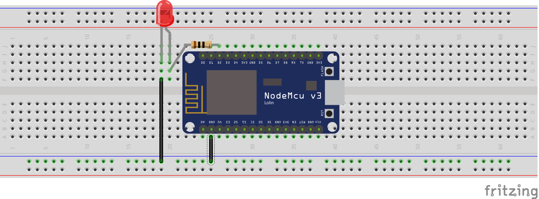
Schematics
For this project, we will do the hello world of embedded programming, which is blinking an LED to demonstrate the use of the nodeMCU, so our schematics involves the connection of an LED to the nodeMCU as shown below.
Schematics
Preparing the Arduino IDE
Before writing the code for the project, it is important to install all the packages necessary to make the board compatible with the Arduino IDE. We will essentially install two things:
The NodeMCU Arduino Core
The ESP8266 library for Arduino.
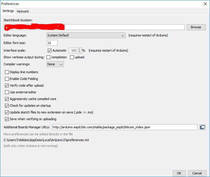
1. The NodeMCU Arduino Core
To make it easier to integrate other open source boards with the Arduino IDE, the Arduino team included a board manager in recent IDEs. Through the board manager, new boards (essentially software-based components required for the Arduino IDE to be able to upload code to a particular MCU) can be added to the IDE. These software-based components called cores are usually developed by manufacturers of the board (like Sparkfun does for its boards) or a group of users with the desire to see their board to work with the Arduino IDE.
The ESP8266 core for the Arduino IDE, which is compatible with the node MCU, was developed by members of the community who were interested in pushing the use of the board and can be found on the ESP8266 Github page.
Follow the steps below to install the board core on the Arduino IDE.
Open the preferences window from the Arduino IDE. Go to File > Preferences
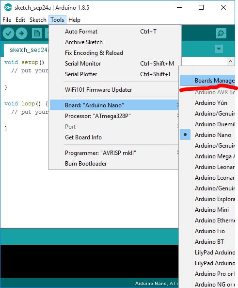
Next, open the Arduino board manager. Go to tools>Boards>Boards manager
Select Board
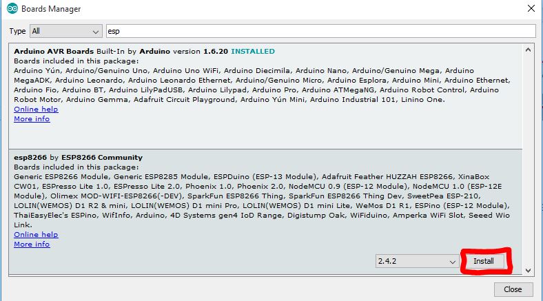
When the board manager opens up, enter ESP into the search bar and scroll to the bottom, you will see ESP8266 created by the ESP8266 community, click on install as shown below.
Install
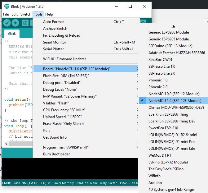
Installing the ESP8266 core will automatically install the ESP8266 library which will make easier writing code for the NodeMCU. After board installation, select the board going to tools>board>NodeMCU 1.0
By selecting this board, all the examples associated with the NodeMCU board will be loaded up. The code for today’s tutorial will be based on one of those examples.
Code
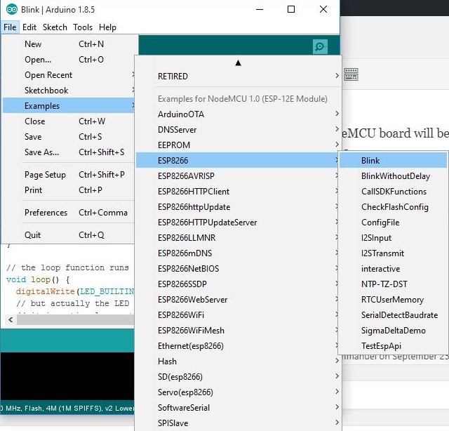
For today’s tutorial, we will blink a LED connected to pin D2 of the NodeMCU using the blink example that came with the core installation we did earlier.
Load the example by going to file>examples>examples for nodemcu>esp8266>blink
Selecting the blink example
The blink example is probably the most common of all the examples associated with the Arduino but for the sake of those, I will explain it a bit.
We start the code by declaring the pin of the NodeMCU to which our LED is connected.
int LEDpin = 2;
Next is the void setup() function. All we need to do under this is to set the pin to which our led is connected as an output.
void setup() {
  pinMode(LEDpin, OUTPUT);     // Initialize pin D2 as an output
}
Lastly, the void loop function. Here we create lines of code to turn the LED on and off after certain intervals to create the blink effect.
void loop() {
  digitalWrite(LEDpin, LOW);   // Turn the LED on (Note that LOW is the voltage level
  // but actually the LED is on; this is because
  // it is active low on the ESP-01)
  delay(1000);                      // Wait for a second
  digitalWrite(LEDpin, HIGH);  // Turn the LED off by making the voltage HIGH
  delay(2000);                      // Wait for two seconds (to demonstrate the active low LED)
}
The complete code is written below.
int LEDpin = 2;

void setup() {
  pinMode(LEDpin, OUTPUT);     // Initialize the LEDpin as an output
}

// the loop function runs over and over again forever
void loop() {
  digitalWrite(LEDpin, LOW);   // Turn the LED on (Note that LOW is the voltage level
  // but actually the LED is on; this is because
  // it is active low on the ESP-01)
  delay(1000);                      // Wait for a second
  digitalWrite(LEDpin, HIGH);  // Turn the LED off by making the voltage HIGH
  delay(2000);                      // Wait for two seconds (to demonstrate the active low LED)
}
Demo
Upload the code to the NodeMCU. After a while, you should see the connected LED start blinking.
The NodeMCU is certainly capable of a whole lot more than has been demonstrated in today’s tutorial but I hope we have been able to get you started and on the next few tutorials we will be able to dive deeper into the use of the board.
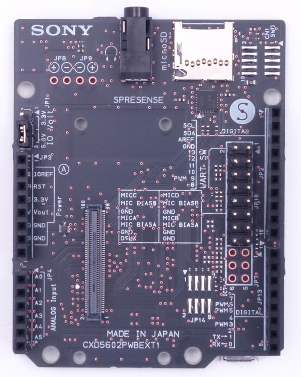
FRAMOS has been appointed as an approved supplier for the Sony’s Spresense product line of professional developer boards in the United States. [via]
These boards are powered by Sony’s 6 core CXD5602 MCU, which are based on an ARM Cortex-M4F with 6 cores operating at up to 156 MHz. The board is supported by the Arduino IDE as well as the NuttX based SDK. It includes GPS support, high-res audio output offering advanced 192kHz/24-bit audio codec and amplifier, and multi-mic inputs supporting up to 8 digital / 4 analogue mic input channels.
Molex’s thin-film battery can be applied to a curved surface with a bend radius of 25 mm or greater.
Molex’s thin-film battery is a low-profile, flexible, disposable battery with a small footprint designed for low-power, single-use applications. This battery can be applied to a curved surface with a bend radius of 25 mm or greater. Its chemical breakdown of zinc, manganese dioxide, and zinc chloride means it has no heavy metals, so it offers an economical, environmentally safe alternative to lithium. The vertically stacked construction provides reduced distance between anode and cathode and gives reduced internal resistance, increased peak current, increased usable capacity, and reduced footprint compared to single-layer construction. Available in 1.5 V and 3.0 V configurations, these batteries deliver power suitable for low-power disposable applications. Thin-film batteries can attach to wearable and medical biosensors and conform to a patient’s body for maximum comfort. The batteries feature an operating temperature range of -35°C to +50°C. They are compliant with the European battery directive 2006/66/EC. Limited exposure to elevated temperatures is recommended due to reduced performance at temperatures below 0°C.
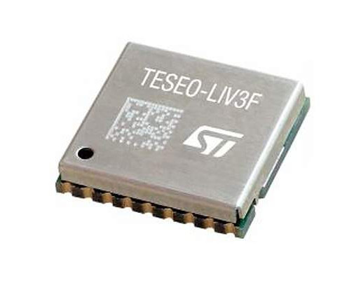
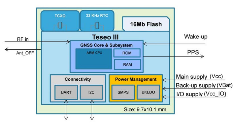
STMicroelectronics lunched the first GNSS module (Global Navigation Satellite System) with the name Teseo-LIV3F. The module is interesting because it contains some cool features. The GNSS module supports GPS, Galileo, GLONASS, QZSS and also BeiDou. The dimension of module is 9.7 x 10.1 mm and the communication interface is standard UART and I2C (100/400KHz).
The Teseo-LIV3F module features temperature-compensated 26 MHz oscillator for higher data accuracy. Furthermore you can use it as real-time clock (RTC).
The I2C address is configurable through “firmware configurator” (PC Tool Teseo-Suite Light) and the firmware can be easily updated. The power consumption of GNSS module can be controlled by two standby modes – software and hardware standby. When you use hardware standby mode, the consumption is wonderful 6 uA and if you use software standby mode you achieve apower consumption of only 12 uA.
The module also features”data logging” properties. The position data can be saved for up to 12 hours with 1 Hz sample rate and you can use standard or circular buffer.
Specifications
Power voltage: 2,1 – 4,3 V
Power consumption: 72 mW (GPS, VCC = 2,1V) or 90 mW (GPS and Glonass, VCC = 2,1V)
Maximal velocity: 515 m/s
Maximal altitude: 18 000 m
Hot start: max 2,5 s
Cold start: max 36 s
Warm start: max 29 s
The price of module is 15 USD and it’s available on digikey.com
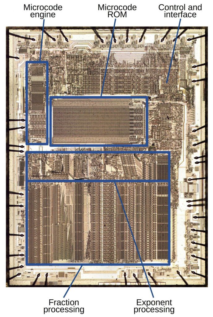
The 8087 chip provided fast floating point arithmetic for the original IBM PC and became part of the x86 architecture used today. One unusual feature of the 8087 is it contained a multi-level ROM (Read-Only Memory) that stored two bits per transistor, twice as dense as a normal ROM. Instead of storing binary data, each cell in the 8087’s ROM stored one of four different values, which were then decoded into two bits. Because the 8087 required a large ROM for microcode1 and the chip was pushing the limits of how many transistors could fit on a chip, Intel used this special technique to make the ROM fit. In this article, I explain how Intel implemented this multi-level ROM.
Two bits per transistor: high-density ROM in Intel’s 8087 floating point chip – [Link]
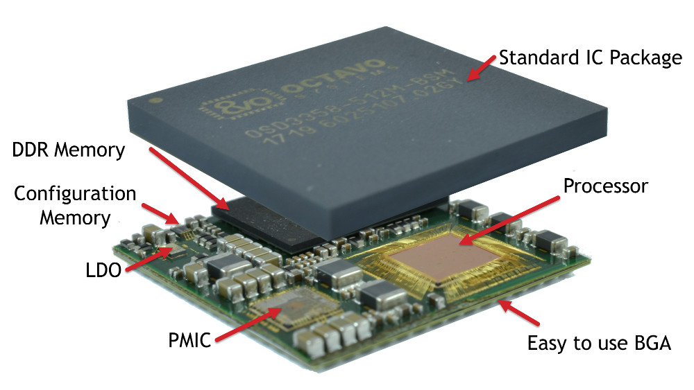
The OSD335x C-SiP System-in-Package (SiP) developed by Octavo, is a concept package that is modeled on its previous Sitara AM335x based SiP by including up to 16GB eMMC, an oscillator along with 1GB DDR3, PMIC, LDO, and EEPROM. The OSD335x C-SiP, is the most consolidated System-In-Package (SiP) module ever made. Modeled like its predecessors, the OSD335x C-SiP incorporates the Cortex-A8 based Texas Instruments Sitara AM3358 SoC with RAM, including the addition of the eMMC and oscillator for the first time and other principal components. The addition of the eMMC and the Oscillator to the processor, RAM and power supplies makes the OSD335x C-SiP a complete system.
Detailed view of the OSD335x C-SiP
The CTO of Octavo Systems Gene Frantz said it has everything one needs for a powerful Linux computer integrated into a small, easy to use package and what is only requires to do is add power and a couple of resistors. That is why it is called a Complete System-In-Package. The advantage of SiPs is that they require less space and someone can achieve easier and speedy development, among other benefits. During an interview with LinuxGizmos, Octavo Systems CTO said they have done most part, by taking on the tedious part of system design for the embedded developers (how to get the processor, memory, PMIC, and other components to work together nicely). With the incorporation of OSD335x C-SiP, many of the monotonous and tedious tasks related to designing a computing system are eliminated. Tasks like laying out DDR3 memory interfaces and power sequencing are no longer needed.
Also, any issue about Electromagnetic Interference (EMI) caused by the layout of the Oscillator is removed. Apart from making a simple design of an embedded system, the OSD335x C-SiP is also about 50% smaller than a corresponding system built with separate components. This allows designers to decrease their design size, save cost on their PCBs, or add processing power to form factors that weren’t possible before. Like the earlier packages, the OSD335x C-SiP offers a TPS65217C PMIC and TL5209 LDO, both from TI. It will also be available in 0 to 85°C and -40 to 85°C models.
The OSD335x C-SiP is packaged with the usual Debian stack and offers open source files including schematics. The design is said to enable full access to AM335x features, including the PowerVR SGX GPU and programmable PRU chips. The module is backwards compatible to the OSD3358-SM-RED, various BeagleBone boards, and other Sitara AM335x hardware. The initial models that are ready for pre-order include the higher-end AM3358 version of the SoC, as well as 512MB of DDR3 and 4GB eMMC. In coming 2019, other models will be fitted including larger memoriy.
The C-SiP may be a bit more expensive than buying the different components separately, but Octavo’s SiP packages have the advantages of not only reducing development cost but also potentially, manufacturing costs. For example, it can reduce the need to add multiple PCB layers or print double-sided boards. Application Engineering Manager of Octavo Systems, Erik Welsh estimated that with the OSD335x C-SiP, designers can get a system working in half the time required to design a discrete solution.
The OSD335x C-SiP can be used in building automation, Industrial Control, Consumers goods, and IoT application.
A Weather station project is a project that gives you information about the weather in a particular area and is quite useful for a lot of things like planning of the day, farming and several others. A weather station project is one of those projects where you can have different types of sensors attached to it. In this post, I will highlight some interesting sensors that can be added to a weather station based project.
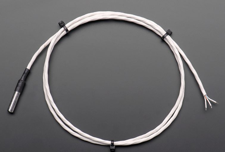
DS18B20 Temperature Sensor
DS18B20
The DS18B20 is a temperature sensor and one of my favorite one. Unlike other temperature sensors, the DS18B20 is one wire type of sensor. It only requires one wire for communication and also supports parasite modes. Parasite mode means it doesn’t need a power supply, and it can get powered from the same data line. One of the features of the DS18B20 and other one-wire sensors is the fact that you connect multiple sensors to just one pin. I have connected about 32 of those sensors to one single digital pin on the Arduino Uno. Continue reading “Interesting Sensors To Add To Your Weather Station Project”