Adafruit Feather RP2040: Another feather board but with a Raspberry Pi microcontroller

Adafruit Feather RP2040

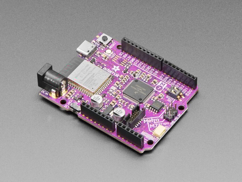
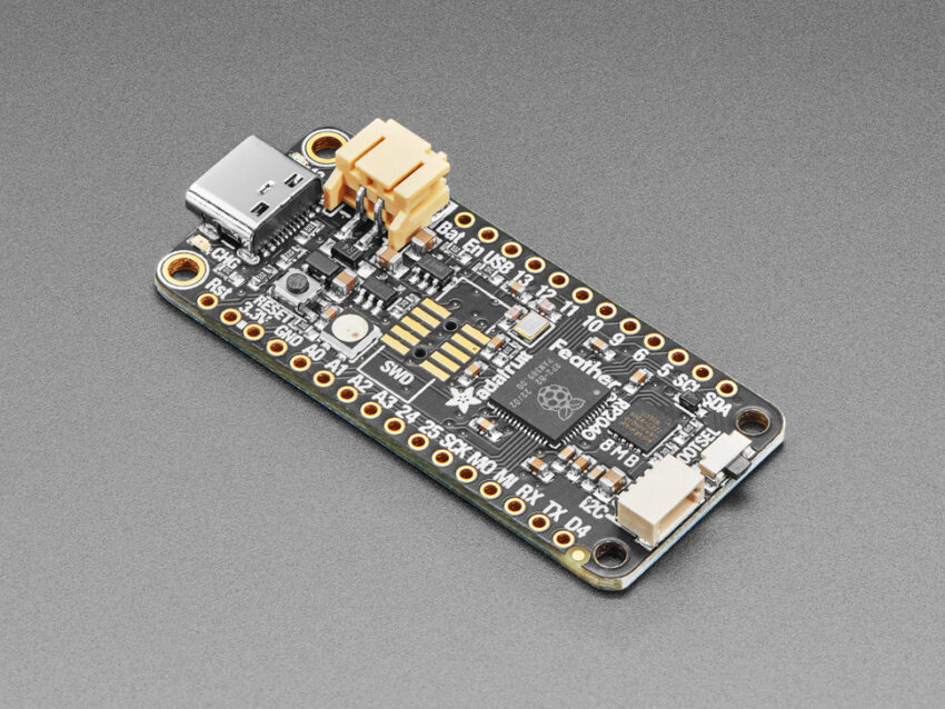
The Adafruit Feather RP2040 is an embedded device with the popular Feather form factor, designed to cater to the needs of long-range IoT wireless communication. At the heart of the Adafruit Feather RP2040 is the Raspberry Pi RP2040 microcontroller, which ensures high performance and low power.

The famous Raspberry Pi RP2040 microcontroller boasts a dual-core Arm Cortex-M0+ processor, running at 133 MHz, providing sufficient processing power for various applications. With 264 kB of SRAM and 8 MB of SPI flash memory, the RP2040 allows for efficient data storage and quick retrieval, ensuring smooth operation.

Specifications of the Adafruit Feather RP2040:

  • Processor: Raspberry Pi RP2040, featuring dual-core Arm Cortex-M0+
  • Storage: 8 MB of SPI flash memory for program and data storage
  • Memory: 264kB RAM
  • Connectivity: RFM95 LoRa radio for long-range wireless communication
  • GPIOs: 21x GPIO pins with four 12-bit ADCs, two I2C, two SPI and two UART peripherals, 16x PWM outputs, and eight digital non-ADC/non-peripheral GPIO
  • Power: 3.3V operating voltage and a built-in USB Type-C port, along with a 2-pin LiPo battery connector
  • Connector: STEMMA QT connector for easy interfacing or I2C devices
  • Button: Reset and bootloader select button
  • Software: Easy bootloader installation for easy programming
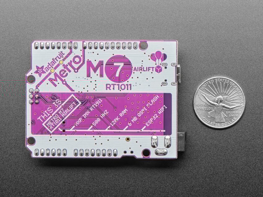
  • Dimensions: 50.8mm x 22.8mm x 7mm

In addition to these specifications, the Adafruit Feather RP2040 offers an array of other features, including a wide range of GPIO pins, allowing users to connect various sensors, actuators, and peripherals. The onboard LoRa radio enables long-range communication, making it suitable for applications requiring remote data transmission over extended distances.

Video

When it comes to software support, the Adafruit Feather RP2040 is backed by Adafruit’s extensive library of Arduino libraries and CircuitPython support. This makes it easy for developers to get started and leverage the vast ecosystem of existing libraries and examples. The RP2040 microcontroller inside the Adafruit Feather RP2040 comes with a built-in USB UF2 bootloader, which is stored in a permanent ROM (Read-Only Memory). This bootloader plays a crucial role when you want to program new firmware onto the board.

Adafruit Feather RP2040 is currently available for purchase at $11.95 USD on its official product page.

Adafruit Metro M7– An Arduino Uno layout board with wireless connectivity

Adafruit Metro M7 board

Adafruit has recently unveiled its Adafruit Metro M7 board, which has an Arduino Uno layout and combines the added convenience of built-in wireless connectivity. With its features and robust hardware, the Metro M7 with AirLift offers a comprehensive platform for a wide range of projects, making it an ideal addition to Adafruit’s extensive lineup of development tools.

At the heart of the Adafruit Metro M7 lies the powerful NXP iMX RT1011 processor. This ARM Cortex-M7-based microcontroller boasts a clock speed of 500 MHz, enabling it to handle complex tasks with ease. The iMX RT1011 processor provides enough processing power for resource-intensive applications, making it a good choice for projects requiring real-time responsiveness and high-speed data processing.

Apart from its powerful processor, the Adafruit Metro M7 board offers a range of other features that enhance its functionality and flexibility. One of its key highlights is the built-in AirLift module, which provides Wi-Fi connectivity. This module is based on the popular ESP32 co-processor, allowing seamless integration with wireless networks and enabling communication with other devices.

Adafruit Metro M7 board vs Coin

Specifications of Adafruit Metro M7 board:

  1. Processor: NXP iMX RT1011 processor featuring Arm Cortex M7 
  2. Co-processor: AirLift WiFi Co-processor with ESP32-WROOM-32 module
  3. Memory: 28KB SRAM
  4. Storage: 8MB of QSPI XIP flash
  5. Power: 6-12VDC barrel jack or USB type-C
  6. Connector: SWD connector for debugging and STEMMA QT connector for interfacing external I2C devices
  7. Dimensions: 53.2mm x 72mm
  8. Weight: 22.5 grams

In terms of software support, the Metro M7 board is compatible with the popular CircuitPython development programming language, making it accessible and user-friendly for both beginners and experienced developers. The same layout as the Arduino Uno means that the user can partially use Arduino Uno accessories for quick and easy integration of various sensors, actuators, and other peripherals into projects, simplifying the prototyping process.

Adafruit has provided detailed documentation on installing the UF2 bootloader on the RT10xx microcontroller to assist users in getting started with the board and leveraging its capabilities.

Adafruit Metro M7 board is currently available for purchase at $29.95 USD on its official product page.

MI997 Mini-ITX Motherboard for 12th Gen Intel Core Processor

IBASE Technology Inc., a leading provider of embedded board and solutions, launches the MI997 Mini-ITX motherboard designed for 12th Gen Intel® Core™ processors (codenamed Alder Lake PS) that supports faster DDR5 memory and takes advantage of a hybrid architecture that combines performance and efficient cores, outperforming previous generations in single-core and multi-core workloads.

The MI997 has two DDR5 SO-DIMM sockets with 64GB capacity, providing higher bandwidth and improved power consumption. M.2 slots (B-key, E-key, 2x M-Key) enable the installation of high-performance storage devices for faster boot and load times, and robust wireless (WiFi, Bluetooth) connections. The MI997 comes with HDMI (2.0a), LVDS, and 2x DisplayPort (1.4a) graphics interfaces, dual Intel 2.5G Ethernet controllers, and an abundance of I/O peripheral connectivity with four USB 3.2, two USB 3.1, and two USB 2.0 ports.

MI997 FEATURES:

  • 12th Gen Intel® Core™ i7/i5/i3 and Celeron® processors (formerly Alder Lake PS)
  • 2x DDR5 SO-DIMM sockets, Max. 64GB
  • Intel® processor integrated graphics supports HDMI (2.0a), LVDS and 2x DisplayPort (1.4a) (DP++)
  • Dual Intel® 2.5G LAN
  • 4x USB 3.2, 2x USB 3.1, 2x USB 2.0, 4x COM, 2x SATA III
  • 1x PCI-E (x1) [Gen.3.0]; 4x M.2 (B-key, E-key and 2x M-Key)
  • Watchdog timer, Digital I/O, iAMT(16.0), fTPM
  • 12V~24V DC input

In addition to its stable performance and advanced connectivity capabilities, the MI997 also features Intel Active Management Technology (iAMT 16.0) for easy remote management, built-in RAID support, fTPM, and 12V to 24V suitable for various industrial environments. Overall, the IBASE MI997 Mini-ITX motherboard is a powerful and reliable IoT edge solution for digital signage, POS/kiosk, and automation control applications.

For more information, please visit www.ibase.com.tw

Join the Open Source Hardware Movement and Fabricate Your Own Wio Terminal for A Chance To Get 2x Free PCBA from Seeed Fusion

Hey Community! Are you ready to unleash your creativity and take the open-source hardware movement to the next level?

We are passionate about open-source hardware and believe that it has the power to transform the world. That’s why we’re taking it to the next level with open manufacturing, making it possible for anyone to reproduce and manufacture the Seeed Studio Wio-Terminal. With the potential to unlock limitless creativity and innovation, the Wio Terminal is more than just a microcontroller – it’s a game-changer!

We are committed to the open-source hardware movement, and in that spirit, we have taken this step further into open manufacturing. We believe that opening the manufacturing process will unlock immense potential for innovation and creativity.

Seeed Studio Wio Terminal is an open-source hardware initiative that we have developed and maintained with passion.

A widely-acknowledged IoT development platform that supports Arduino and MicroPython and equipped with Bluetooth and Wi-Fi, the Wio Terminal has already made its mark in smart homes, industrial automation, education and research.

We are now offering all the production files and documentation required to modify and  manufacture the Wio Terminal, enabling anyone to replicate, produce, and even commercialize their own versions of this amazing device. We believe that open manufacturing will facilitate innovation and encourage more people to participate in hardware design and improvement, collectively promoting the development of hardware technology. We can’t wait to see the amazing things that you will create with the Wio Terminal, and we encourage you to share your designs and ideas on our platform.

Exploring more about Wio-Terminal: Fabricatable Open Source Hardware on Seeed Studio’s Github


These design files are freely available for anyone to access, use and modify. For convenience, we also include these design files in the Wio Terminal wiki .

We are looking for partners who share our philosophy to promote the development of open-source hardware and open manufacturing together. Whether you are a corporation, educational institution, research institution, or individual developer, as long as you have passion and innovation, we welcome you to join us. Let’s build an open, innovative, and fair hardware ecosystem together.

Fusion Quick Pass

In order to give back to our community and make your great ideas a reality, Seeed Studio Fusion is launching the Wio Terminal open source movement to help capable engineers, individual developers turn their designs into real products.

For those who wish to design and manufacture their own versions of Wio Terminal, our SeeedStudio Fusion Agile manufacturing offers quick and high-quality PCB Assembly service. One more thing to clarify is that please make sure that you are capable of designing and have all the production files ready for us. Moreover, once your idea/proposal is approved by us, each person is limited to two PCBA boards 100% completely FREE for one Wio Terminal design, including PCB fabrication, the cost of parts, assembly and free worldwide delivery.

Getting excited? Keep reading to find out more.

How to join the open source hardware movement and fabricate your own wio terminal and get a $30 Cash Prize?


How to join the open source hardware movement and fabricate your own wio terminal?

  • Please fill out the form: https://forms.gle/uic7bVA8SnuJLFR3A to submit your Wio Terminal design proposal.
  • One more thing to clarify is that please make sure that you are capable of designing and have all the production files ready for us. If we approve your design proposal, we will contact you via email & Linkedin as soon as possible, then you can start to prepare your Gerber & BOM file. (Pls note that when preparing your BOM file, please preferentially select materials in Seeed Fusion OPL, which will speed up the production of your order.)
  • All of design files are freely available for anyone to access, use and modify. You can explore more about Wio-Terminal: Fabricatable Open Source Hardware on Seeed Studio’s Github.
  • If you have any questions, please do not hesitate to contact our Seeed Fusion customer support team at fusion@seeed.io for further consultation.

What kind of secondary development and design can you do based on the Wio Terminal?

Here are some initial ideas we’ve provided to help you get started.

1. Modification of Wio Terminal Boards

You can modify the interfaces according to your needs and make suitable changes to the casing. Don’t hesitate to fill out the form and share your design thoughts with us to receive a sponsorship of 2PCS free PCB Assembly. If you share your final project with us and receive over 20 likes on Seeed Studio’s Twitter or LinkedIn, we are willing to offer you a cash prize of $30USD.

2. Wio Terminal Peripheral Accessories Design

Peter, a developer from the community, has designed a QWERTY keyboard for Seeed Studio’s Wio Terminal that operates without an IC. The keyboard matrix is scanned through GPIO and the software is programmed using CircuitPython. We encourage you to submit your innovative ideas for accessory design based on Wio Terminal by filling out the form and sharing them with us.

Scale up your Wio-Terminal Creation with Seeed Studio Co-Create Program!

We will invite well received wio-terminal designs to the Seeed Studio Co-Create Program, where your products can be listed, sold and shipped directly by Seeed on the Seeed Studio Bazaar. We will also support designers to reach thousands of like-minded customers and distributors with Seeed’s global sales channels and social media presence.

Join the Open Manufacturing Movement Together!

Manufacturing and Assembling your Wio Terminal design with the help of Seeed Fusion PCBA Agile Manufacturing Service. Then, publish your Wio Terminal designs on your own platform and we would love to share them on Seeed Studio social media.

 * By participating in this event, you agree to review your experience with us and allow us to share the design with the community on our social media platforms (Facebook, Twitter, Linkedin, discord, blog, etc.). The design does not need to be open-sourced and production files will not be shared with the public (unless you want to).

We’re excited to take this journey with you. Let’s create, innovate, and shape the future of open manufacturing together!

Installation of Casa OS on Raspberry Pi

In this tutorial, I will show you how to build a beautiful home server with Raspberry Pi and CasaOS.

Things Needed

All you need is a Raspberry Pi 4B board, That’s all.

Introduction to Casa OS

CasaOS is a simple, easy-to-use, elegant open-source home cloud system that allows you to run self-hosted apps on your Raspberry Pi or other Linux devices. You can manage your files, share them across the network, protect your private data, and freely add disks and expansion spaces. CasaOS also has an app store with over 20 pre-installed Docker-based apps and 50+ community-verified apps.

If you want to try out the casa os before the installation, use this demo site.

The username is casaos, and the password is also the same.

CasaOS fully supports Raspberry Pi. Also, additional computers and development boards are fully compatible including Ubuntu, Debian, Raspberry Pi OS, and CentOS with one-liner installation.

Get PCBs for Your Projects Manufactured (Sponsor)

It’s recommended to check out PCBWAY for ordering PCBs online for cheap!

You get 10 good-quality PCBs manufactured and shipped to your doorstep for cheap. You will also get a discount on shipping on your first order. Upload your Gerber files onto PCBWAY to get them manufactured with good quality and quick turnaround time. PCBWay now could provide a complete product solution, from design to enclosure production. Check out their online Gerber viewer function. With reward points, you can get free stuff from their gift shop.

Hardware Compatibility

  • amd64 / x86-64arm64armv7

System Compatibility:

  • Debian 11 (✅ Tested, Recommended)
  • Ubuntu Server 20.04 (✅ Tested)
  • Raspberry Pi OS (✅ Tested)

Quick Setup of CasaOS

Now we have enough information about the Casa, let’s try to install it. Before installing the casa, first boot your Raspberry Pi with Raspian OS. Use the Raspberry Pi imager tool to do that.

Once installed, the software opens the tool.

Next, choose the OS type.

Then select the drive. One of the great features of this tool is we can add the SSH and Wi-Fi credentials directly into the OS file, even without turning on the Raspberry Pi. For that, select the settings icon in the tool.

Next, start burning the OS into the SD card.

Once the writing is finished, insert the SD card into the Raspberry Pi.

Then power on the device. The first time it will take some time to boot and connect to Wi-Fi. In about 5–10 minutes look at your router status, and you can see there will be a new device connected to your router.

Next, use serial terminal software to communicate with SSH.

Then run this command to install the CasaOS.

curl -fsSL https://get.casaos.io | sudo bash

You will see this message on the terminal, and the entered command will try to install all the necessary components regarding the CasaOS.

Once the installation is finished, you will see this kind of message also the IP address of the Casa Server.

Next type the IP in your Brower, and you will see the CasaOS on screen.

And then click Go and enter your access details for the CasaOS.

Finally, you will see the beautiful home screen.

Next, click on the app store, and you can see there is a bunch of available apps.


Also, open the file manager, and you will see all the files of your Raspberry Pi,

Not only the system drive, but It will show you the removable drive also.

Wrap-Up

That’s all about the CasaOS, it’s a very beautiful, simple, and lightweight OS, right? And it also includes a bunch of apps, including Pihole, Plex, and many more.

Will see you in another tutorial.

Brushed DC Motor Speed Controller Using Radio Control (RC) Remote

This is a Brushed DC motor controller designed to control one brushed DC motor up to 5A. It can control the speed of the DC motor using a Radio Control (RC) System. This Arduino compatible hardware converts RC PWM signal into 0 to 100% duty cycle PWM which further drives high current load using MOSFET. The project consists of an Atmega328 microcontroller, and a gate driver optocoupler provides isolation between MOSFET and microcontroller circuit to prevent high voltage and noise traveling from the motor and related circuit to the microcontroller. The circuit can drive a motor up to 5A with a power supply of 12V to 40V DC. The board has the option to mount higher voltage and current MOSFET, which can drive higher Voltage and current load. In this case don’t install Q2, install Q1 MOSFET FDH3632, and replace diode D2 with a higher current diode.

Note: This board will work with any standard RC remote. In this project, we tested it with HOTRC DS-600 6CH 2.4GHz Radio System. Standard RC radio outputs is 50Hz – 1mS(1000uS) to 2mS(2000uS)

Arduino Programming

Arduino code is available as a download below and the user will able to test the board using this code. Feel free to modify the code as per requirement.

More info for programming a new Atmega328 chip: https://docs.arduino.cc/built-in-examples/arduino-isp/ArduinoToBreadboard

Power Supply

  • For Motor up to 12-15V the board can work with a single supply. Close jumper J1 and Jumper J2, and use connector CN1 to apply 12V to 15V DC.
  • For Higher Voltage up to 90V (Limited due to DC bus capacitor), the board requires dual supply, one for DC motor load, 2nd for gate driver 12V to 15V on CN3.
  • It is advisable to use 3 separate power supplies for large-size motors such as 90V, 20A. such as 1. Logic supply 5V. 2. Gate Driver Supply 12V to 15V and Load supply 90V DC.
  • Use Connector CN1 for load power supply up to 90V DC, Gate driver requires 12V to 15V power at CN3, and use CN5 Pin 1-5V DC and Pin 3 GND to power the microcontroller.

Features

  • Power Supply up to 40V (Read description for higher power input)
  • Load Current Up to 5Amps
  • Dual Supply 12V-15V DC for Gate driver and 40V for the Load
  • On Board Power LED
  • Optocoupler MOSFET Gate driver for noise immunity and provides isolation between micro-controller and MOSFET
  • Arduino Compatible Hardware to create many applications
  • On Board Connector for Arduino Programming and Boot-Loader burring
  • Barrier Terminal Blocks for easy connection of Motor and power supply
  • Onboard 5V Regulator for single supply operation for lower voltage motor
  • PCB Dimensions 74.45 x 52.23 mm
  • 4 x 3mm Mounting Holes

Connections and Other Details

  • CN1: Pin 1 = + DC Supply for Load, Pin 2 = GND
  • CN2: DC Brushed Motor, Pin 1 = Motor, Pin 2= Motor
  • CN3: Gate Driver Power Supply 12V to 15V, Pin 1 = +12V to 15V, Pin 2 = GND
  • CN4: Programming and Boot-Loader, Pin 1 = TX, Pin 2 = RX, Pin 3 = Reset, Pin 4 = GND, Pin 5 = VCC, Pin 6 = D11, Pin 7 = D12, Pin 8 = D13
  • CN6: RC Receiver, Pin 1 = D3 – RC PWM Input, Pin 2 = VCC 5V, Pin 3 = GND
  • J1: For lower voltage single supply option, Close Jumper 1, Jumper J2, Use CN1 to power 12V to 15V DC.
  • J2: For Lower Voltage motor 12V to 15V Close Jumper J2 to power the Gate driver
  • For Higher Voltage motor such 90V, advisable to use three power supply, Load Supply CN1, Gate driver Supply 12V to 15V CN3, Logic supply 5V CN5, open jumper J1 and J2 in this case
  • CN5: Do not Install
  • D3: Power LED

Schematic

Parts List

NOQNTYREF.DESC.MANUFACTURERSUPPLIERSUPPLIER'S PART N0
11CN12 PIN BARRIER CONNECTOR PITCH 9.53MMTE CONNECTIVITYDIGIKEYA98482-ND
21CN22 PIN BARRIER CONNECTOR PITCH 9.53MMTE CONNECTIVITYDIGIKEYA98482-ND
31CN32 PIN SCREW TERMINAL PITCH 5.08MMPHOENIXDIGIKEY277-1247-ND
41CN48 PIN MALE HEADER PITCH 2.54MMWURTHDIGIKEY732-5321-ND
52CN5,CN63 PIN MALE HEADER PITCH 2.54MMWURTHDIGIKEY732-5316-ND
63C1,C6,C7100nF/50V CERAMIC SMD SIZE 0805YAGEO/MURATADIGIKEY
71C210uF/16V CERAMIC SMD SIZE 0805YAGEO/MURATADIGIKEY
81C3100nF/100V THT FILMCORNELLDIGIKEY160104K160C-F-ND
91C4470uF/100V ELECTROLYTICNICHICONDIGIKEY493-1379-ND
101C5220uF/25V ELECTROLYTICRUBYCONDIGIKEY1189-2913-ND
112SHUNTSHUNT FOR JUMPER J1 AND J2SULINS CONNCTDIGIKEYS9001-ND
123D1,R6,C8DNP
132C9,C1022PF/50V CERAMIC SMD SIZE 0805YAGEO/MURATADIGIKEY
141D2MBR20200CTG TO263ONSEMIDIGIKEYMBR20200CTGOS-ND
151D3LED RED SMD SIZE 0805OSRAMDIGIKEY475-1278-1-ND
162J1,J2JUMPER 2PIN MALE HEADER PITCH 2.54MMWURTHDIGIKEY732-5315-ND
171Q1FDH3632 OPTIONAL TO247 ON SEMIDIGIKEYDO NOT INSTALL
181Q2IRFZ44 INFINEODIGIKEYIRFZ44NSTRLPBFTR-ND
191R110K 5% smd size 0805YAGEO/MURATADIGIKEY
201R2470E 5% smd size 0805YAGEO/MURATADIGIKEY
211R34.7E 5% SMD SIZE 0805YAGEO/MURATADIGIKEY
221R40E SMD SIZE 0805YAGEO/MURATADIGIKEY
231R51M 5% SMD SIZE 0805YAGEO/MURATADIGIKEY
241R71K 5% SMD SIZE 0805YAGEO/MURATADIGIKEY
251U1LM78M05 SMD DPAKTIDIGIKEYMC78M05CDTGOS-ND
261U2ATMEGA328TQPF-32MICROCHIPDIGIKEYATMEGA328PB-AURCT-ND
271U3TLP350/TLP250TOSHIBADIGIKEYTLP350F-ND
281X116MhzECS INCDIGIKEYX1103-ND

Connections

Gerber View

Photos

Video


TLP350 Datasheet

RC Radio Controlled Switch with Relay

This RC Relay project enables control of large current devices using a Radio Control (RC) System. This RC switch converts hobby radio control (RC) pulses to control the on/off state of the Relay. On board LED indicates the output. The board is Arduino compatible and the example code can be modified as per user requirements.  The relay ON/OFF threshold can be set as per user requirements. The Arduino sample code enables momentary ON/OFF control of the relay, but this can be modified for Latch output. The relay can handle a load up to 7A – 30V DC or 7 Amps 230AC Loads such as bulbs, LEDs, motors, fans, heaters etc. The project can be connected to an unused RC channel. It operates with 5V DC and draws 60mA current when the relay is ON. 3 Pin male header helps the user to connect the RC receiver. The project is Arduino compatible and can be programmed using Arduino IDE with the help of an onboard programming connector. The project consists of an Atmega328 microcontroller, programming/bootloader connector, relay, BC847 BJT transistor to drive the relay, freewheel diode for protection from the relay, and U2 PC817 provides isolation between the microcontroller and relay. D1 LED indicates output, D3 LED power LED. connector CN2 relay switch connection, connector CN1 5V supply input.

Note: This board will work with any standard RC remote. In this project, we tested it with HOTRC DS-600 6CH 2.4GHz Radio System. Standard RC radio outputs is 50Hz – 1mS(1000uS) to 2mS(2000uS)

Arduino Programming

Arduino Code is available as a download below. The user will be able to operate the Relay while the RC radio joystick is pulled down and the pulse width is between 1460 – 1090uS. The user may change this value in the code. Connector CN3 is provided to burn the bootloader and upload the Arduino code. Please refer to the connection diagram for programming.

More info about new Atmega328 chip programming: https://docs.arduino.cc/built-in-examples/arduino-isp/ArduinoToBreadboard

Arduino Code Credits: “Tech Home” YouTube Channel

Features

  • Supply 5V DC
  • Current 60mA when Relay is On
  • RC Signal 1000 to 2000 uS
  • Relay Switch Activate Threshold Time 1460 – 1090uS
  • Relay Output-Load 230V AC Up to 7Amps, 30V DC up to 7Amps
  • On Board Power LED
  • On Board Output LED
  • Header Connector for RC Receiver Interface
  • 4 x 2.5mm Mounting Holes
  • PCB Dimensions 66.68 x 22.23mm

Connections and Other Details

  • CN1: Pin 1 = VCC, Pin 2 = GND
  • CN2: Relay Switch/Output Pin 1 = Normally Closed, Pin 2 = Common, Pin 3 = Normally Open
  • CN3: Programming Connector Pin 1= TX, Pin 2 = RX, Pin 3 = Reset, Pin 4 = GND, Pin 5 = VCC, Pin 6 = D11, Pin 7 = D12, Pin 8 = D13
  • CN4: RC Receiver Pin 1 = RC Pulse Input, Pin 2 = VCC, Pin 3 = GND
  • D1: Relay Output LED
  • D3: Power LED

Schematic

Parts List

NOQNTYREF.DESCMANUFACTURERSUPPLIERSUPPLIER'S PART
11CN12 PIN MALE HEADER PITCH 2.54MMWURTHDIGIKEY732-5315-ND
21CN23 PIN SCREW TERMINAL PITCH 5.08MMPHOENIXDIGIKEY277-1248-ND
31CN38 PIN MALE HEADER PITCH 2.54MMWURTHDIGIKEY732-5321-ND
41CN43 PIN MALE HEADER PITCH 2.54MMWURTHDIGIKEY732-5315-ND
52C1,C310uF/16V CERAMIC SMD SIZE 0805YAGEO/MURATADIGIKEY
62C2,C40.1uF/50V CERAMIC SMD SIZE 0805YAGEO/MURATADIGIKEY
71C5DNP
82C6,C722PF/50V CERAMIC SMD SIZE 0805YAGEO/MURATADIGIKEY
92D1,D3LED RED-GREEN SMD SIZE 0805OSRAMDIGIKEY475-1278-1-ND
101D21N4007 SMD DIODEDIODE INCORP.DIGIKEYS1MBDITR-ND
111Q1BC847AL SMD SOT223NEXPERIADIGIKEY1727-2924-2-ND
121RL1Relay 5VCIT RELAYDIGIKEY2449-J107F1CS125VDC.36-ND
132R1,R61K 5% SMD SIZE 0805YAGEO/MURATADIGIKEY
141R210K 5% SMD SIZE 0805YAGEO/MURATADIGIKEY
152R3,R52K2 5% SMD SIZE 0805YAGEO/MURATADIGIKEY
161R4470E 5% SMD SIZE 0805YAGEO/MURATADIGIKEY
171R71M 5% SMD SIZE 0805YAGEO/MURATADIGIKEY
181R84.7E 5% SMD SIZE 0805YAGEO/MURATADIGIKEY
191U1ATMEGA328TQPF-32MICROCHIPDIGIKEYATMEGA328PB-AURCT-ND
201U2PC817 DIP4AMERICAN BRIGHTDIGIKEYBPC-817(BBIN)-ND
211X116MhzECS INCDIGIKEYX1103-ND

Connections

Gerber View

Photos

3


Video

PC817 Datasheet

Video Driver with Built-in 6 Channel Input Selection Switch

The project presented here is a video driver with 6 channel input selection using onboard jumpers or a microcontroller interface. The circuit features a wide dynamic range and frequency response. The IC can be used with low voltage starting at VCC=2.8V and the project supports a broad range of input signals, depending on whether or not a 6-dB video and video driver is included and what combination of sync tip clamp type and bias (resistor terminal) type input is used. RCA connectors are provided for video input and output connection. The header connector helps to power the board. Jumpers J2 to J3 are provided to select the input channels. 6-channel video selection can also be controlled using an external circuit or microcontroller by applying high or low TTL signal to CTLA, CTLB, CTLC, CTLD pins. In this case, use the center pins of jumper J1 to J4.

Features

  • Power supply voltage, from 2.8 V to 5.5 V
  • Wide output dynamic range
  • Excellent frequency response 100kHz/10MHz 0dB[Typ.]
  • No crosstalk between channels (Typ. -65 dB, f = 4.43 MHz)
  • Built-in standby function, circuit current during standby is 0 µA (Typ.)
  • Sync tip clamp input
  • Video Amplifier Gain 6dB
  • 6-dB amp and 75Ohms driver are built-in
  • Maximum Output Level 3.8Vpp (f=10Khz, THD=1%)
  • Input Voltage Range o to VCC+0.2V
  • Control Pin Switch Level 1.2V Minimum High Level, 0.45V Maximum Low-Level Threshold Voltage
  • Input Impedance 150K Ohms
  • PCB Dimensions 91.44 x 48.10mm
  • 4 x 3mm Mounting Holes

Connections and Other Details

  • CN1: RCA Female = Video Input 1
  • CN3: RCA Female = Video Input 2
  • CN4: RCA Female = Video Input 3
  • CN5: RCA Female = Video Input 4
  • CN6: RCA Female = Video Input 5
  • CN7: RCA Female = Video Input 6
  • CN2: RCA Female = Video Output
  • CN8: Pin 1, 2 = VCC, Pin 3, 4 = GND
  • Jumper J1: Control D
  • Jumper J2: Control C
  • Jumper J3: Control B
  • Jumper J4: Control A
  • D1: Power LED

Input Selection Jumper J1 – J4

  • IN1 = J1=H, J2=L, J3=L, J4=L
  • IN2 = J1=H, J2=L, J3=L, J4=H
  • IN3 = J1=H, J2=L, J3=H, J4=L
  • IN4 = J1=H, J2=L, J3=H, J4=H
  • IN5 = J1=H, J2=H, J3=L, J4=L
  • IN6 = J1=H, J2=H, J3=L, J4=H
  • Mute = J1=H, J2=H , J3=H, J4=X
  • STBY = J1=Open/L , J2=X, J2=X, J4=X
  • X= L(Open)Or H Either Is Possible

Schematic

IC Block Diagram

Parts List

NO.QNTY.REFDESC.MANUFACTURERSUPPLIERSUPPLIER'S PART
17CN1,CN2,CN3,CN4,CN5,CN6,CN7RCA JACKKEYSTONEDIGIKEY36-973-ND
21CN8SIP4WURTHDIGIKEY732-5317-ND
36C1,C9,C11,C13,C15,C174.7uF/50V ELECTROLYTIC 5.30 X 6.50MMKEMETDIGIKEY399-6687-2-ND
41C2470uF/25VRUBYCONDIGIKEY1189-1588-2-ND
51C310uF/25V Ceramic SMD SIZE 1210 or 1206YAGEO/MURATADIGIKEY
62C4,C6100nF/50V CERAMIC SMD SIZE 0805YAGEO/MURATADIGIKEY
71C5100uF/16V OR 25V ELECTROLYTIC NICHICONDIGIKEY493-9418-2-ND
88R4,C7,C8,C10,C12,C14,C16,C18DNPDIGIKEY
91D1LED RED SMD SIZE 0805LITE ON INCDIGIKEY160-1427-1-ND
104J1,J2,J3,J42 PIN MALE HEADER PITCH 2.54MMWURTHDIGIKEY732-5315-ND
111R11K 5% SMD SIZE 0805YAGEO/MURATADIGIKEY
127R2,R3,R5,R6,R7,R8,R975E 1% SMD SIZE 0805YAGEO/MURATADIGIKEY
131U1BH76360FV-E2CT-NDROHMDIGIKEYBH76360FV-E2CT-ND
144SHUNT FOR JUMPERJUMPER SHUNT FOR J1,J2,J3,J4SULINS CONCTDIGIKEYS9001-ND

Connections

Gerber View

Photos

Video

BH76360FV Datasheet

Linear Current Source LED Driver with Dimmer Input

The compact module shown here is a linear current source for LED driver and it’s ideal for automotive LED lighting applications. The project is built using a TLD1211 chip from Infineon. The board provides supply to LEDs under the severe condition of automotive applications resulting in constant brightness and extended LED lifetime. The project is capable to drive high current, high brightness LEDs. The circuit features overload, short circuit, over-voltage, and over-temperature protections. It also has the option to control the LED brightness control by an external PWM signal.

The project can provide an output current of up to 2.5A. You will need to choose the appropriate booster transistor Q1 and sunt resistor R5 to achieve this output. Please refer to the datasheet of the chip for more info.

Dimmer: LED brightness control is possible with an external PWM signal. In this case, you can use the enable pin to feed a PWM signal to control the brightness of the LED. For full current/full brightness apply 5V to Enable Pin or change resistor R1 to 12K and connect it to a 24V LED supply to enable the output.

Features

  • Operating Voltage 8 to 24V (Maximum 28V)
  • Load Current 300mA
  • Constant Current Output
  • Enable Input for PWM Brightness or ON/OFF
  • Over Voltage Protection
  • Very low Standby Current
  • PCB Dimensions 36.04 x 22.54mm
  • 2 x 2.5mm Mounting Holes

Connections and Other Details

  • CN1: Pin 1,2 = VCC, Pin 3, 4 = GND
  • CN2: Pin 1 = Enable or PWM Enput, Pin 2 = GND
  • CN3: Pin 1, 2 = +LED , Pin 3,4 = -LED

Schematic

Parts List

NO.QNTY.REF.DESCMANUFACTURERSUPPLIERSUPPLIER'S PART NO
12CN1,CN34 PIN MALE HEADER PITCH 2.54MMWURTHDIGIKEY732-5317-ND
21CN22 PIN MALE HEADER PITCH 2.54MMWURTHDIGIKEY732-5315-ND
31C1100nF/50V CERAMIC SMD SIZE 0805YAGEO/MURATADIGIKEY
41C210uF/35V CERAMIC SMD 1206 OR 1210YAGEO/MURATADIGIKEY
51Q1MJD3055ONSEMIDIGIKEYMJD3055-ND
61R11.8K 5% SMD SIZE 0805YAGEO/MURATADIGIKEY
71R21K 5% SMD SIZE 0805YAGEO/MURATADIGIKEY
81R3820E 5% SMD SIZE 0805YAGEO/MURATADIGIKEY
91R4100E 5% SMD SIZE 0805YAGEO/MURATADIGIKEY
101R50.5E/2W 1% SMD SIZE 2512YAGEO/MURATADIGIKEY
111U1TLD1211 SOIC8INFINEONDIGIKEYTLD1211SJFUMA1TR-ND

Connections

Gerber View

Photos

Video


TLD1211 Datasheet

TOP PCB Companies