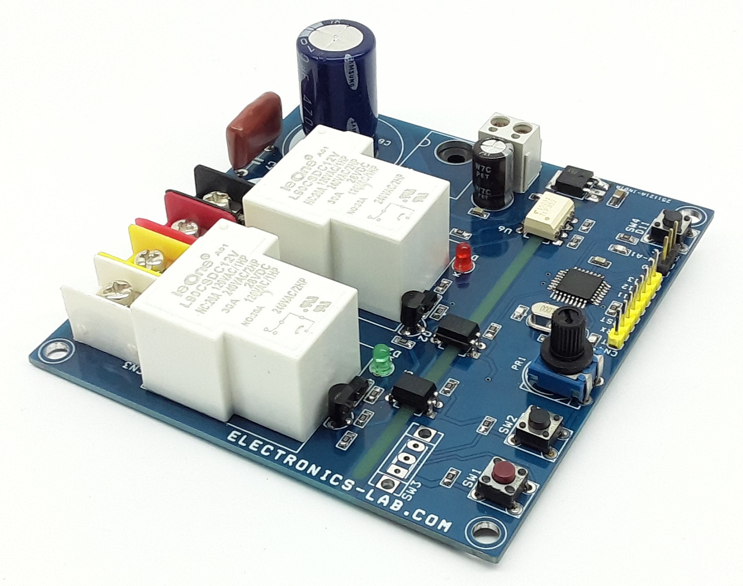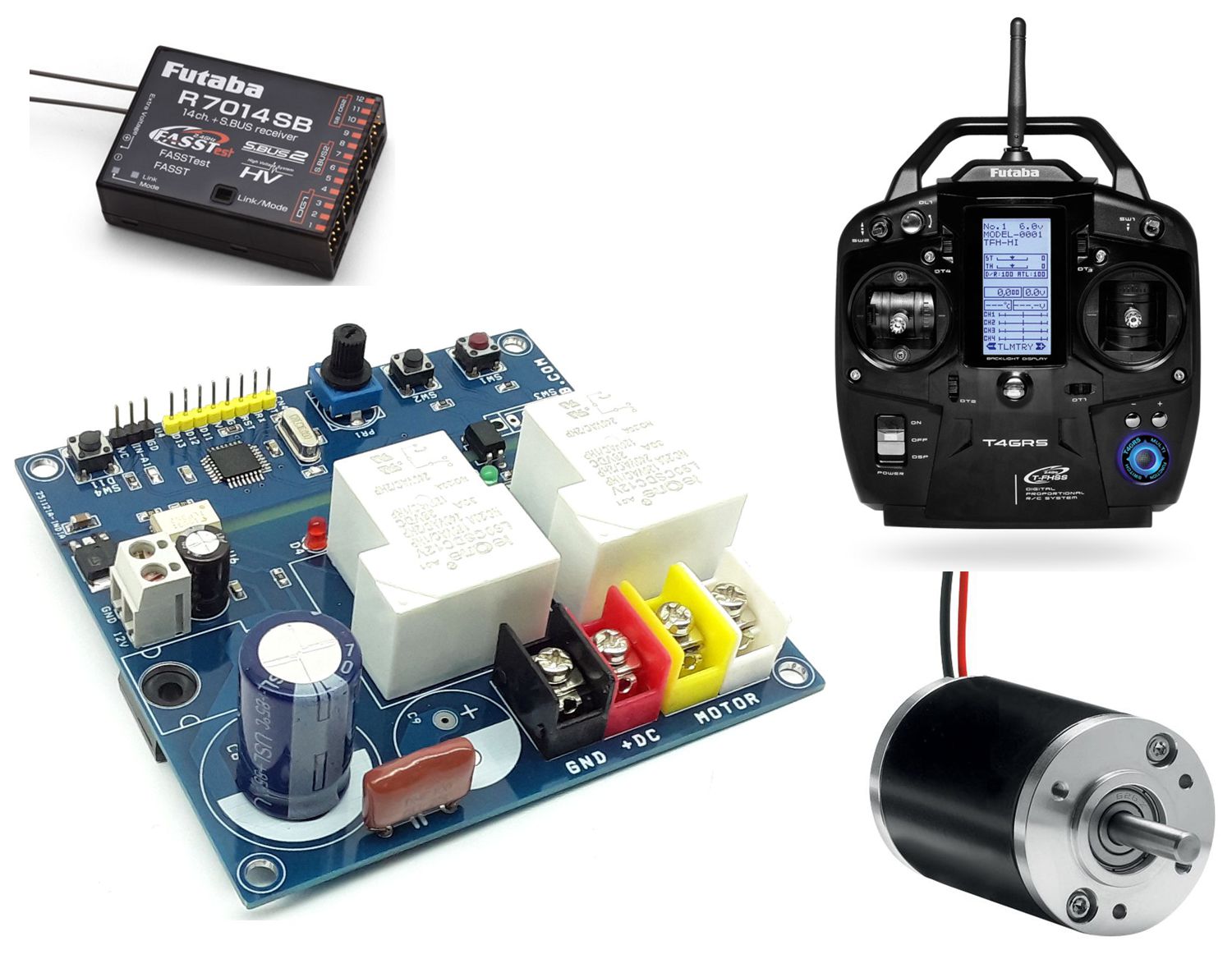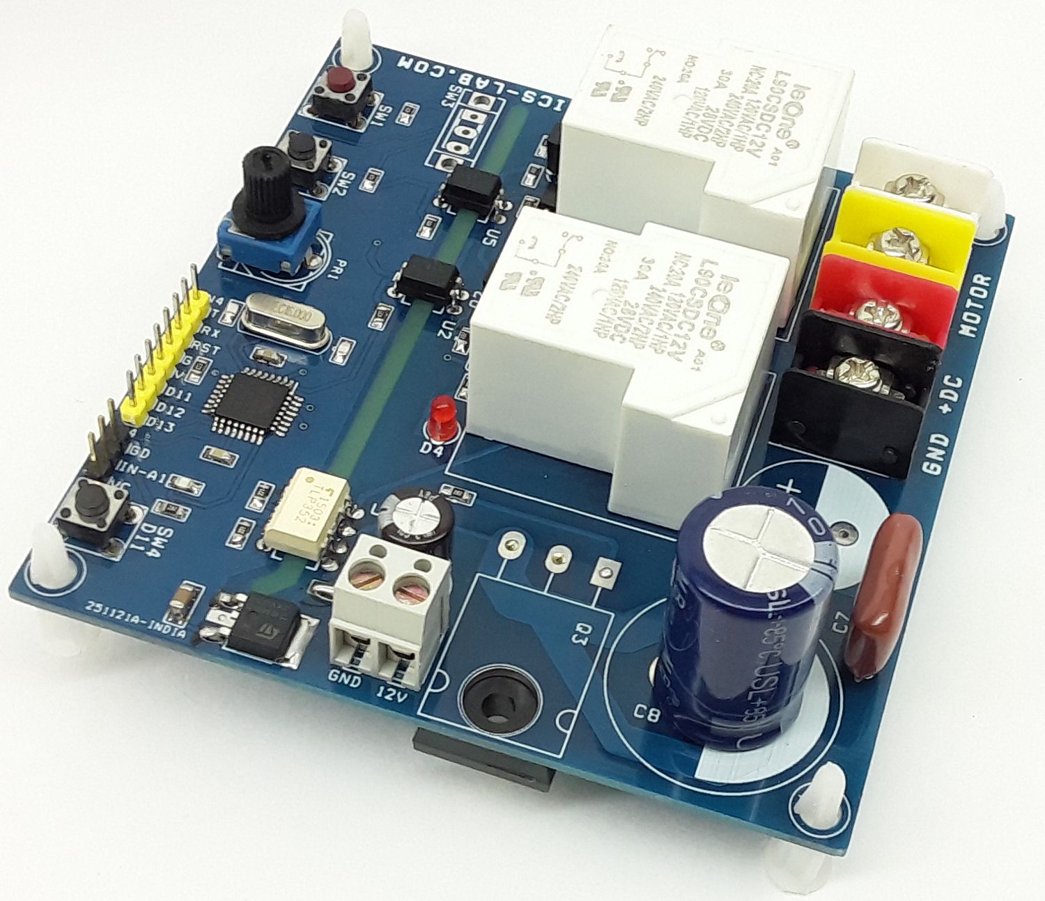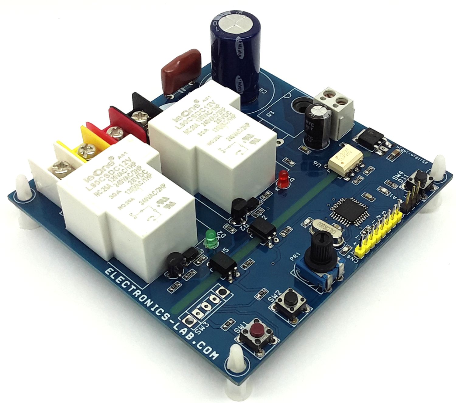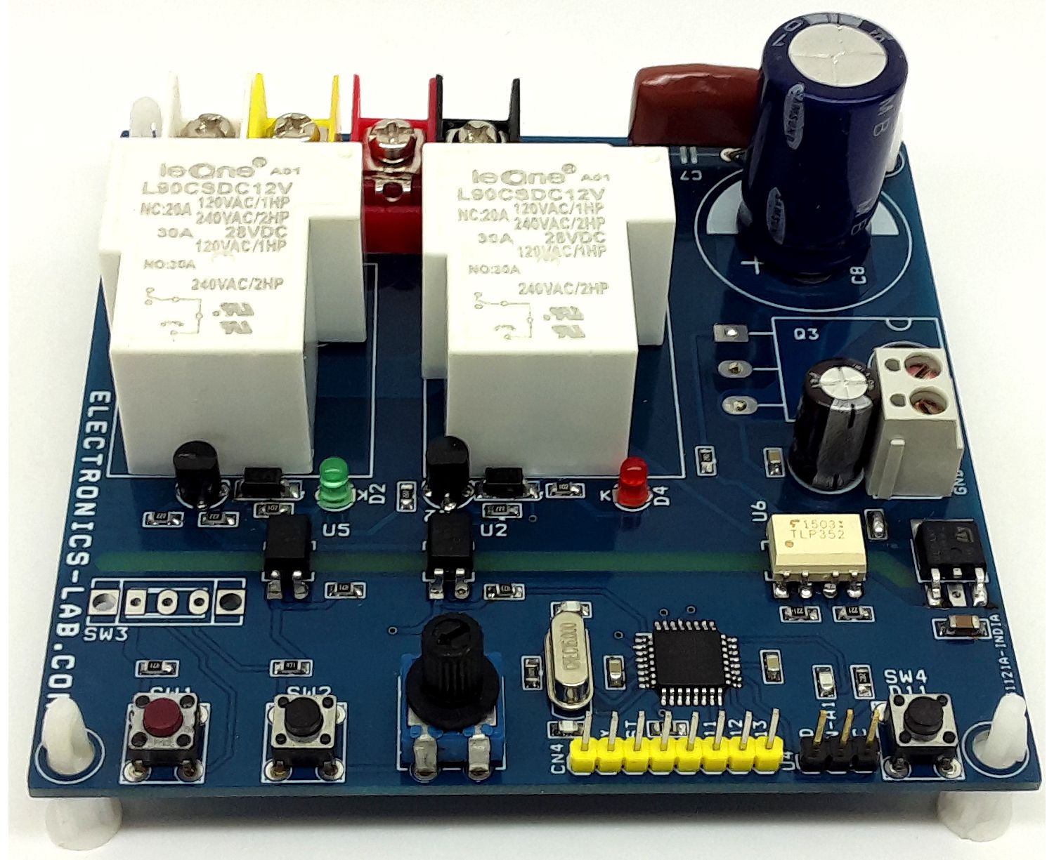
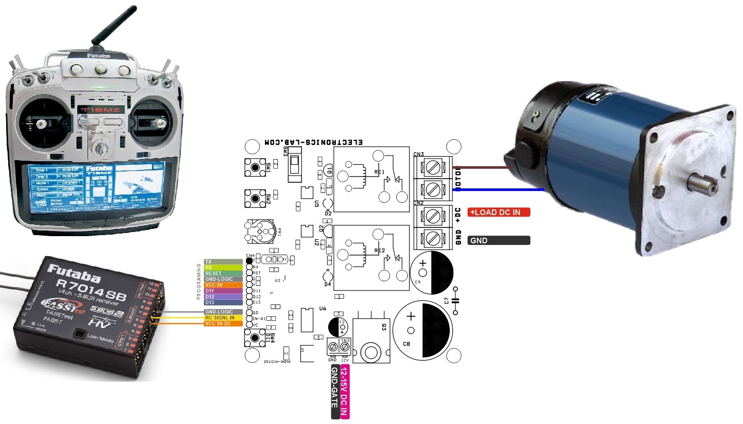
The project presented here is a low-cost solution to control the speed and direction of a high-power brushed DC motor using RC (Radio Remote Control) transmitter. This is an Arduino-compatible board, consisting of an Atmega328 chip, 2 x Relay for motor direction control, MOSFET for speed control using PWM input, Tactile switch, Slide switch, and Connector for RC Receiver interface. Traditional DC motor controllers are based on solid-state circuitry known as H-Bridge. Here the H-bridge configuration is created using 2x high-power Relays which can handle high voltage as well as high current. Additionally, MOSFET Q3 is used to control the speed of the motor by applying a PWM signal. This MOSFET can be removed in case of only direction control is required. In this case short the Drain and source pin of MOSFET. The project requires 3 control input signals 2 x CCW/CW direction control, and 1x PWM input. All inputs are optically isolated to prevent noise and high voltage going into logic circuitry. A large size of heatsink is a must for MOSFET.
Arduino Code and Programming
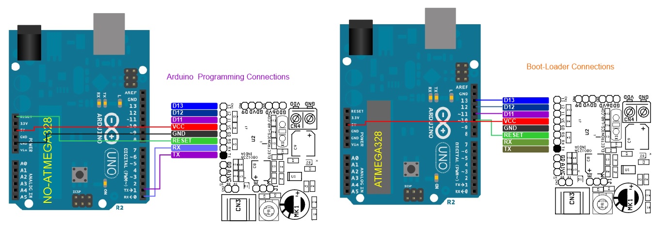
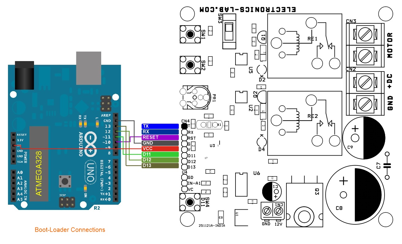
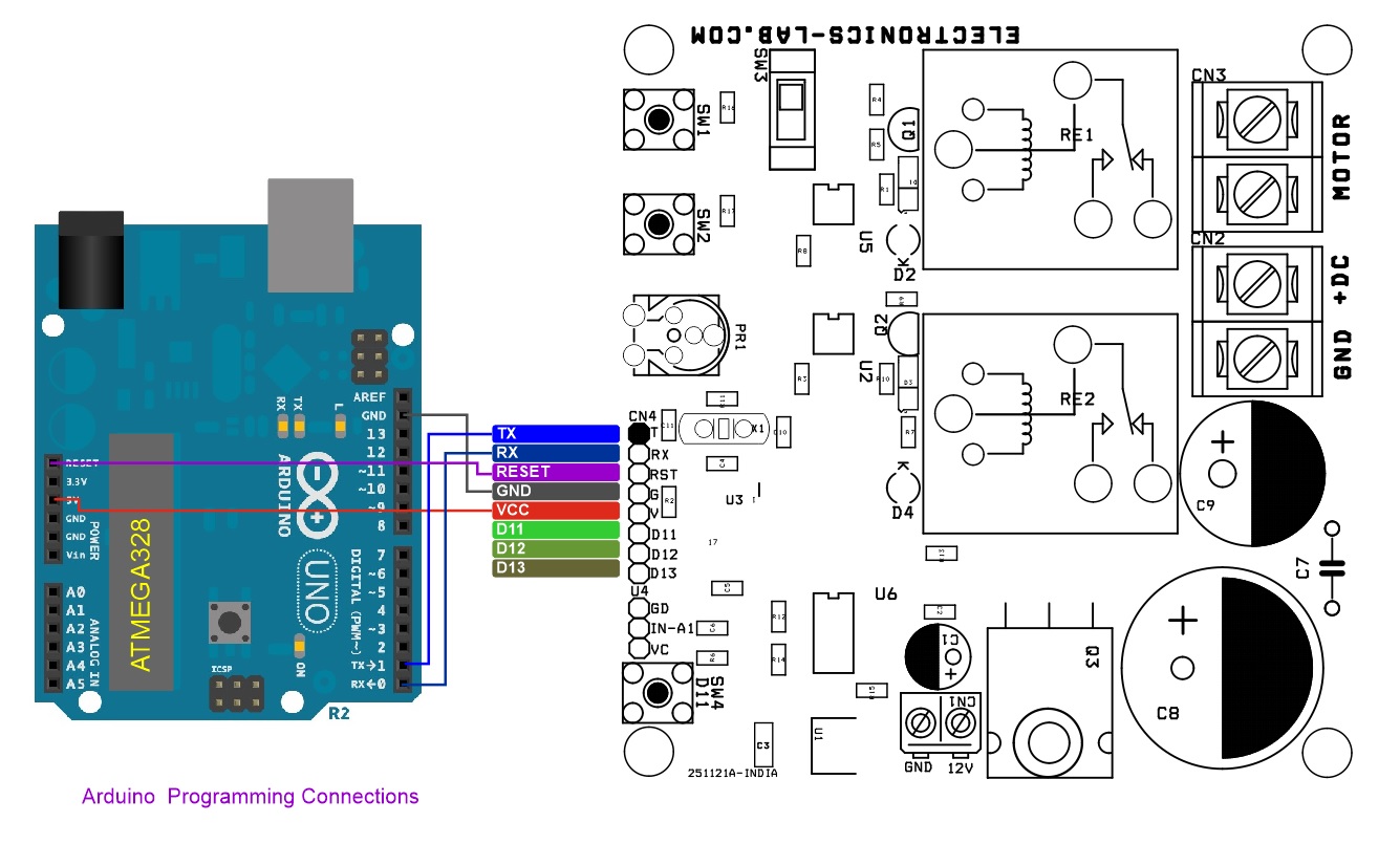
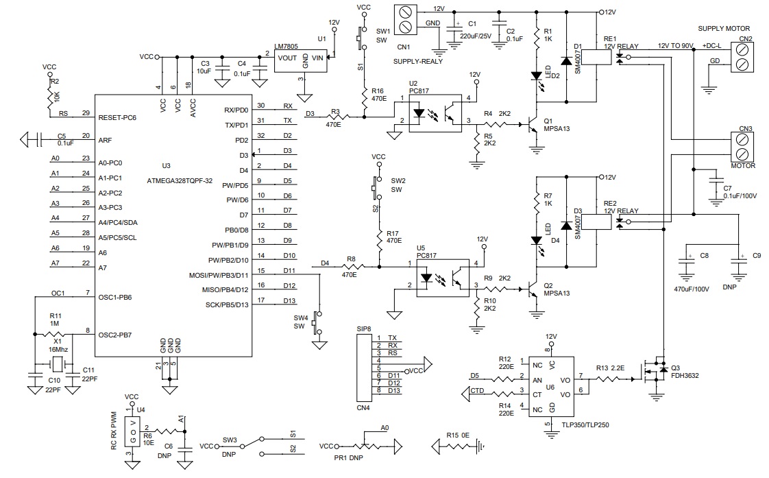
A new ATmega328 chip requires a bootloader. Refer to the connection diagram for the Arduino boot-loader and Arduino programming. The Arduino example code is available as a download. The user will able to control the speed and direction of the brushed DC motor using RC remote Joystick. Connector U4 is provided to connect the RC receiver. ATMEGA328 chip reads the RC signal and generates 2 x CW/CCW TTL signals for motor direction control and one PWM signal. Two direction control signals control the Relay RE1 and RE2, contacts of relay configured in such a way where bidirectional output is provided to the motor, MOSFET drives the PWM signal for motor speed control. All three signals have optocouplers U2, U5, and U6 between motor control circuitry and ATMEGA328 chip which provides noise immunity and high voltage/current going to the digital circuitry.
Arduino Code Credits: modified code, original author Tech at Home Channel
More Info, Boot-Loader, and Arduino Programming: https://docs.arduino.cc/built-in-examples/arduino-isp/ArduinoToBreadboard
Features
- Power Supply for Relay and MOSFET 12V to 15V DC @ 100mA
- Power Supply Motor 12V to 90V DC (Maximum 100V DC)
- Motor Load 20Amps (Maximum 30Amps)
- Optocoupler Between Micro-Controller U1 and 2X Relays and MOSFET for optical isolation
- 2 x Inputs for Direction Control and Brake
- One PWM Signal to Control the speed of Motor 0 to 100 % Duty Cycle
- PWM Frequency up to 20Khz
- 2x LEDs for direction indication
- PCB Dimensions 97 x 93.82mm
- 4 x 4mm Mounting Holes
Arduino Pin
- Arduino Digital Pin D3 and D4 = Relay Control, DC Motor Direction Control, D3 High – D4 Low = CCW, D3 Low – D4 High = CW
- Arduino Digital Pin D5 = MOSFET Gate Driver (PWM for Motor Speed Control) – Duty Cycle (0 to 100%) Frequency up to 20Khz
Read below for the power supply requirements. The project works well with 2 power inputs. One for the MOSFET Gate Driver/Logic supply and 2nd for the motor supply. Advisable to use 3 power inputs for complete isolation between the motor output power driver and the logic circuit.
Power Supply: The project requires 3 power inputs for complete isolation between the microcontroller and motor output power driver.
- 5V Logic supply (Do not solder U1 LM7805 and R15) for full isolation between Micro-Controller U3 and motor output power 2 X Relay and MOSFET Q3, Use Pin 4 and Pin 5 of CN4 for 5V Power Input
- 12V to 15V DC supply for MOSFET gate driver
- Motor Power Supply 12V to 90V DC
The project also can work well with only 2 power inputs
- 12V to 15V DC Gate Driver (Solder U1 LM7805 and Resistor R15) for Dual power input.
- Motor Supply 12V to 90V
Single Power Supply for 12V to 15V Motor
- The project can work with a single supply for a lower voltage (12-15V) motor, Install U1 LM7805, R15 Resistor.
- Tie GND-Pin2 + GD-Pin2 and +12V-Pin1 + DC-L Pin 1 of the CN1 and CN2 and apply 12V to 15V
Arduino-compatible hardware consists following important components which can be used for various applications as per user requirements.
- ATMEGA328 Microcontroller
- MOSFET to control the Speed of the motor with the help of PWM (Arduino Digital Pin D5)
- 2 x Relay for Motor Direction Control (Arduino Digital Pin D3 and D4)
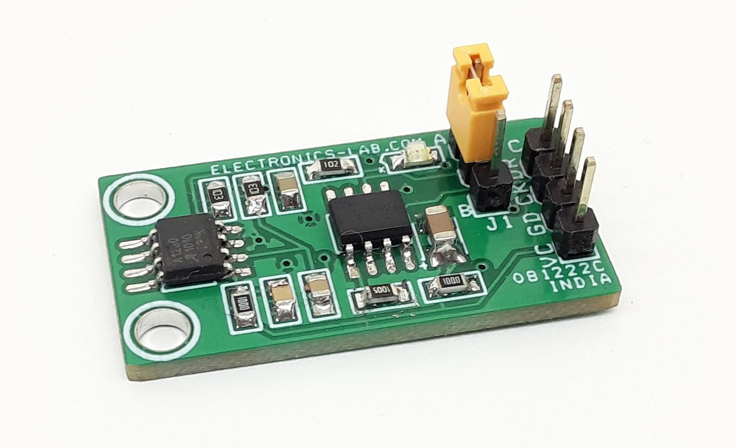
- 3 Pin Header to Connect Radio Remote Receiver or Analog Input (Arduino A1) – Connector U4
- Trimmer Potentiometer for Analog Input (Arduino A0) – Don’t Install for this project
- CN4: Arduino Programming and Boot-Loader Connector
- SW1, SW2 = Tactile Switch (Optional) Control the Relay 1 and Relay 2 Directly – Don’t Install for this project
- SW3: Slider Switch for Direct Direction Control – Don’t Install for this project
- SW4: Tactile Switch Arduino Digital Pin D11
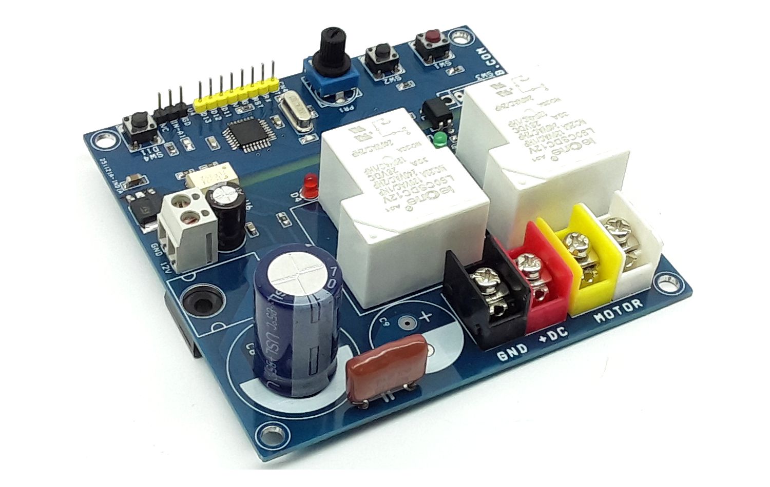
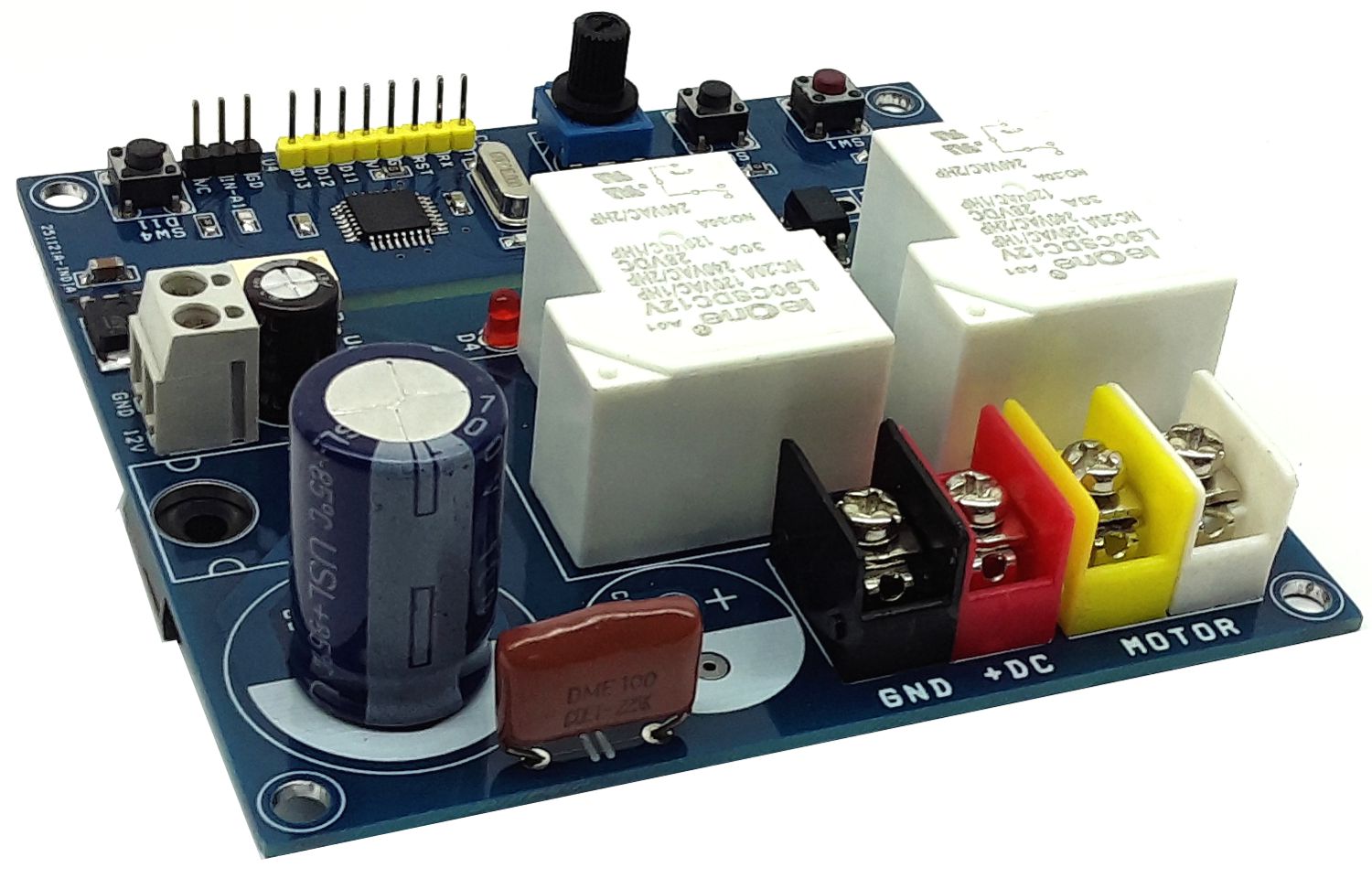
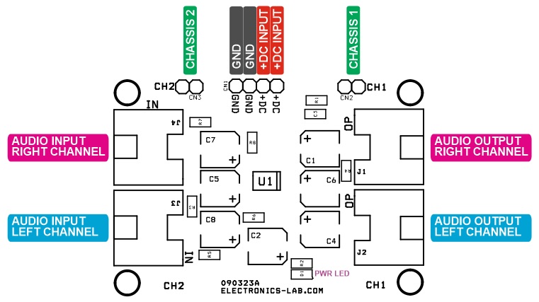
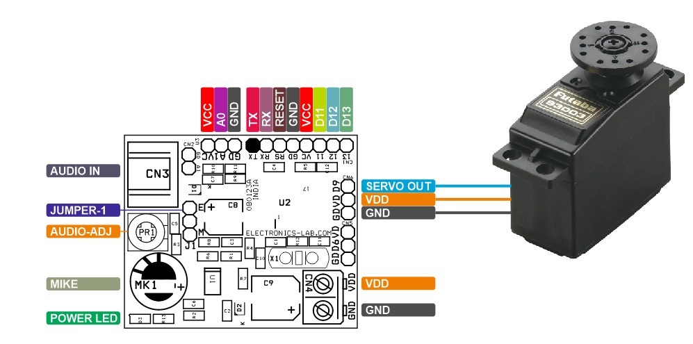
Connections and Other Details
- CN1: Pin 1 = 12V DC for MOSFET Gate Driver, Pin 2 = GND
- CN2: Pin 1 = +Motor Power Supply 12V to 90V DC, Pin 2 = GND
- CN3: Pin 1 = Motor, Pin 2 = Motor
- CN4: Programming Connector Pin 1 = TX, Pin 2 = RX, Pin 3 = Reset, Pin 4 = GND, Pin 5 = VCC, Pin 6 = D11, Pin 7 = D12, Pin 8 = D13
- D2, D4 LED = Motor Direction LED
- SW1, SW2: Optional Direction Switch
- SW3: Optional Direction Switch
- SW4: Optional Switch Connected to Arduino D11
- U4: RC Receiver or Analog In (Arduino Analog A1)
- PR1: Potentiometer Connected to Arduino Analog A0
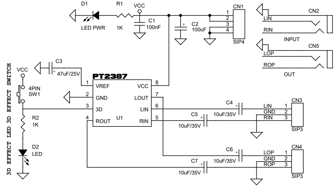
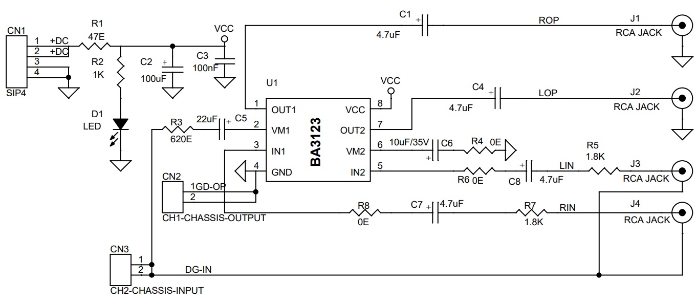
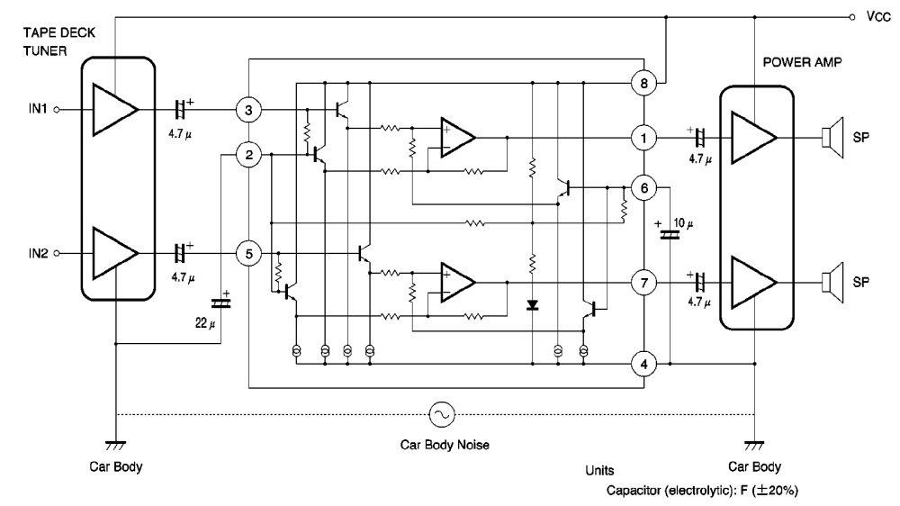
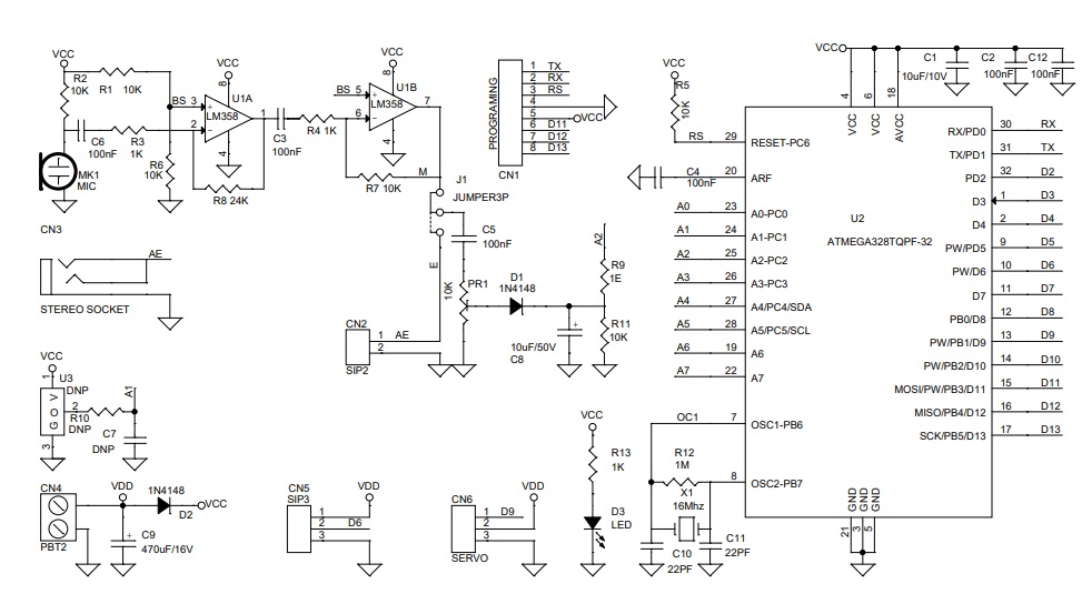
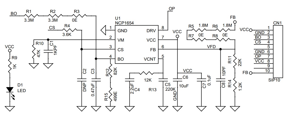
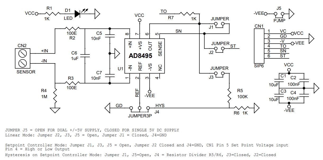
Schematic
Parts List
| NO | QNTY | REF | DESC | MANUFACTURER | SUPPLIER | SUPPLIER'S PART NO |
|---|---|---|---|---|---|---|
| 1 | 1 | CN1 | 2 PIN SCREW TERMINAL PITCH 5.08MM | PHOENIX | DIGIKEY | 277-1247-ND |
| 2 | 1 | CN2 | 2 PIN BARRIER BLOCK PITCH 9.53MM | TE CONNECTIVITY | DIGIKEY | |
| 3 | 1 | CN3 | 2 PIN BARRIER BLOCK PITCH 9.53MM | TE CONNECTIVITY | DIGIKEY | |
| 4 | 1 | CN4 | 8 PIN MALE HEADER PITCH 2.54MM | WURTH | DIGIKEY | 732-5321-ND |
| 5 | 1 | C1 | 220uF/25V | RUBYCON | DIGIKEY | 1189-3720-3-ND |
| 6 | 3 | C2,C4,C5 | 0.1uF/50V CERAMIC SMD SIZE 0805 | YAGEO/MURATA | DIGIKEY | |
| 7 | 1 | C3 | 10uF/25V CERAMIC SMD SIZE 1206 | YAGEO/MURATA | DIGIKEY | |
| 8 | 4 | PR1,SW3,C6,C9 | DO NOT INSTALL | |||
| 9 | 1 | C7 | 0.1uF/100V | VISHAY | DIGIKEY | BFC2373FF104MD-ND |
| 10 | 1 | C8 | 470uF/100V | NICHICON | DIGIKEY | 493-1683-ND |
| 11 | 2 | C10,C11 | 22PF/50V CERAMIC SMD SIZE 0805 | YAGEO/MURATA | DIGIKEY | |
| 12 | 2 | D1,D3 | SM4007 | SMC DIODE | DIGIKEY | 1655-1N4007FLCT-ND |
| 13 | 2 | D2,D4 | LED 3MM RED OR RED + GREEN | AMERICAN OCTO | DIGIKEY | 2460-L314HD-ND |
| 14 | 2 | Q1,Q2 | MPSA13 | ON SEMI | DIGIKEY | 2156-MPSA13RA-ND |
| 15 | 1 | Q3 | FDH3632 | ON SEMI | DIGIKEY | FDH3632FS-ND |
| 16 | 2 | RE1,RE2 | 12V RELAY/30A | CIT RELAY AND SWITCH | DIGIKEY | 2449-L115F11CM12VDCS.9-ND |
| 17 | 2 | R1,R7 | 1K 5% SMD SIZE 0805 | YAGEO/MURATA | DIGIKEY | |
| 18 | 1 | R2 | 10K 5% SMD SIZE 0805 | YAGEO/MURATA | DIGIKEY | |
| 19 | 4 | R3,R8,R16,R17 | 470E 5% SMD SIZE 0805 | YAGEO/MURATA | DIGIKEY | |
| 20 | 4 | R4,R5,R9,R10 | 2K2 5% SMD SIZE 0805 | YAGEO/MURATA | DIGIKEY | |
| 21 | 1 | R6 | 10E 5% SMD SIZE 0805 | YAGEO/MURATA | DIGIKEY | |
| 22 | 1 | R11 | 1M 5% SMD SIZE 0805 | YAGEO/MURATA | DIGIKEY | |
| 23 | 2 | R12,R14 | 220E 5% SMD SIZE 0805 | YAGEO/MURATA | DIGIKEY | |
| 24 | 1 | R13 | 2.2E 5% SMD SIZE 0805 | YAGEO/MURATA | DIGIKEY | |
| 25 | 1 | R15 | 0E SMD SIZE 0805 | YAGEO/MURATA | DIGIKEY | |
| 26 | 3 | SW1,SW2,SW4 | 4 PIN TACCTILE SWITCH | NKK SWITCH | DIGIKEY | HP0215AFKP2-ND |
| 27 | 1 | U1 | LM78M05 DPAK | ON SEMI | DIGIKEY | MC78M15ABDTRKGOSCT-ND |
| 28 | 2 | U2,U5 | PC817 4 PIN THT | AMERICAN BRIGHT | DIGIKEY | BPC-817(BBIN)-ND |
| 29 | 1 | U3 | ATMEGA328TQPF-32 | MICROCHIP | DIGIKEY | ATMEGA328PB-AURCT-ND |
| 30 | 1 | U4 | 3 PIN MALE HEADER PITCH 2.54MM | WURTH | DIGIKEY | 732-5316-ND |
| 31 | 1 | U6 | TLP350/TLP250 8 PIN DIP | TOSHIBA SEMI | DIGIKEY | TLP350H(F)-ND |
| 32 | 1 | X1 | 16Mhz | ECS INC | DIGIKEY | X1103-ND |
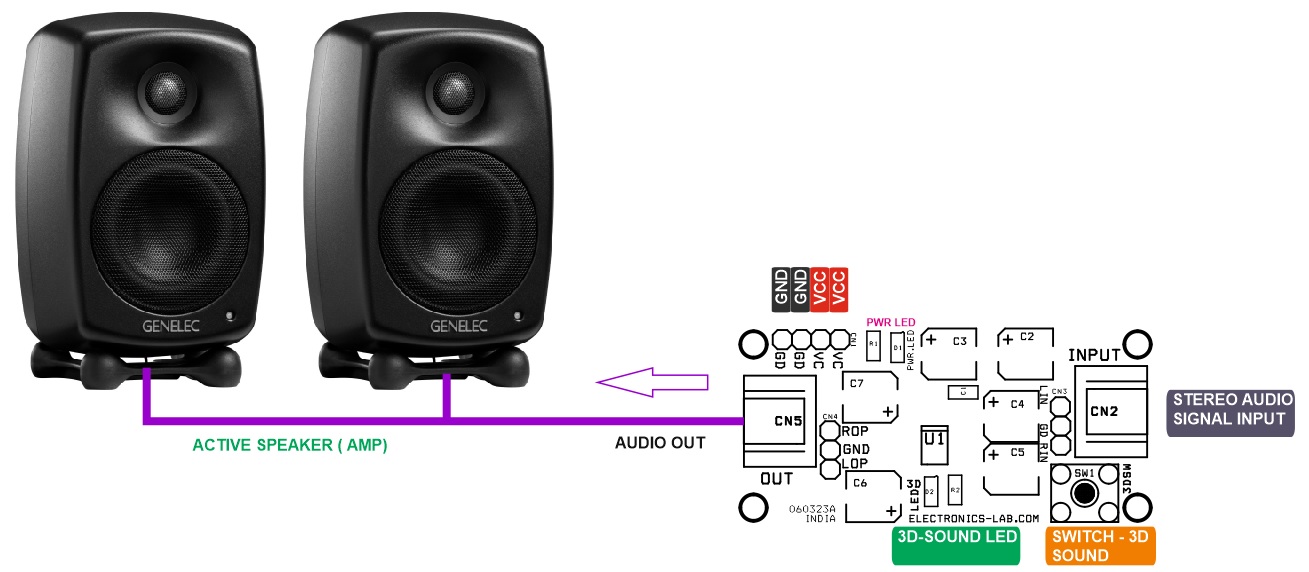
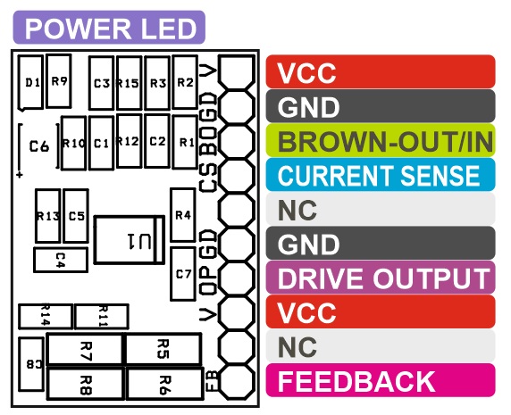
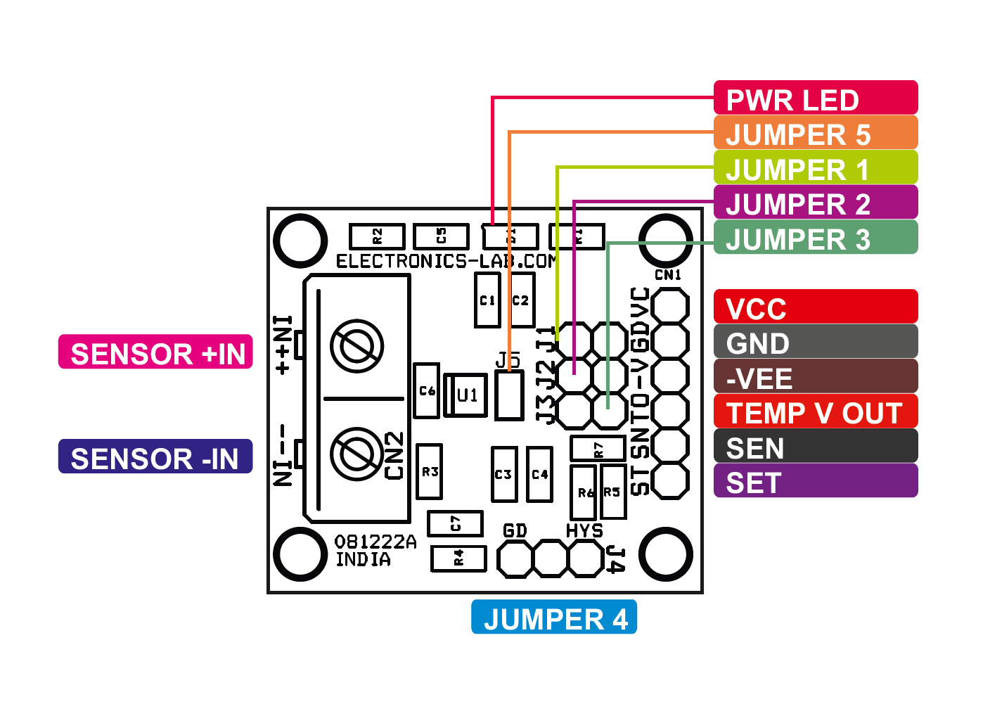
Connections
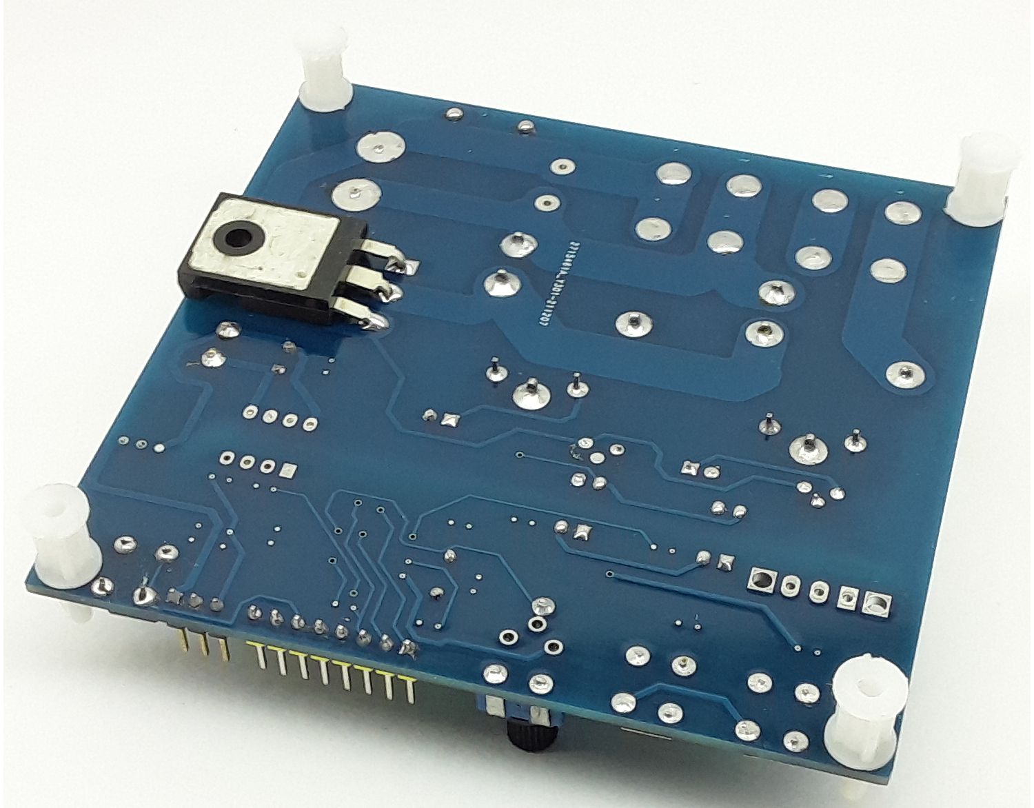
Gerber View
Code
//This is modified code, orignal code from YouTube|Tech at Home

int in1 = 3;
int in2 = 4;
int enable1 = 5;  // pin with ~ symbol

int channel_2 = A1;  // pin with ~ symbol

void setup()
{
  pinMode(channel_2, INPUT);
  pinMode(in1, OUTPUT);
  pinMode(in2, OUTPUT);
  pinMode(enable1, OUTPUT);
  Serial.begin(9600);
}

void loop() {

  int pwm = 0;
  int value = pulseIn(channel_2, HIGH, 25000);

  if(value==0)
  {
      digitalWrite(in1, LOW);
      digitalWrite(in2, LOW);
      analogWrite(enable1, 0);
  }

  else if(value > 1530)
  {
      pwm = map(value, 1530, 1930, 0, 255);
      digitalWrite(in1, LOW);
      digitalWrite(in2, HIGH);
      analogWrite(enable1, pwm);
  }

  else if(value < 1460)
  {
      pwm = map(value, 1460, 1090, 0, 255);
      digitalWrite(in1, HIGH);
      digitalWrite(in2, LOW);
      analogWrite(enable1, pwm);
  }

  else
  {
      digitalWrite(in1, LOW);
      digitalWrite(in2, LOW);
      analogWrite(enable1, 0);
  }

  delay(10);
}
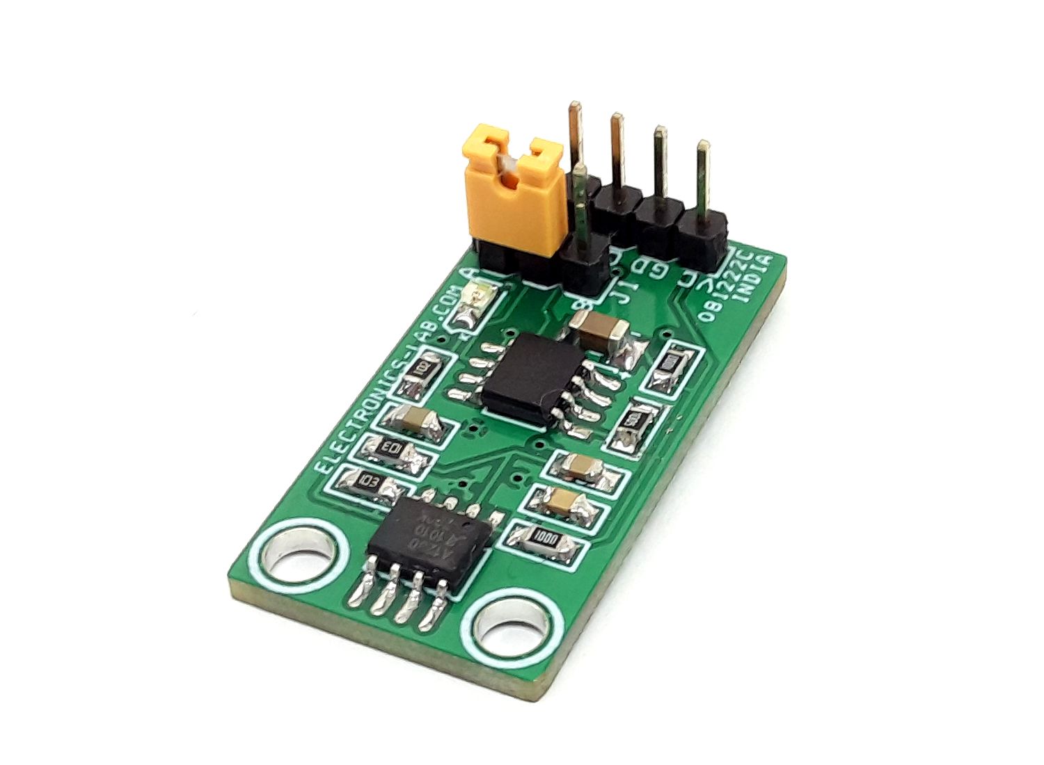
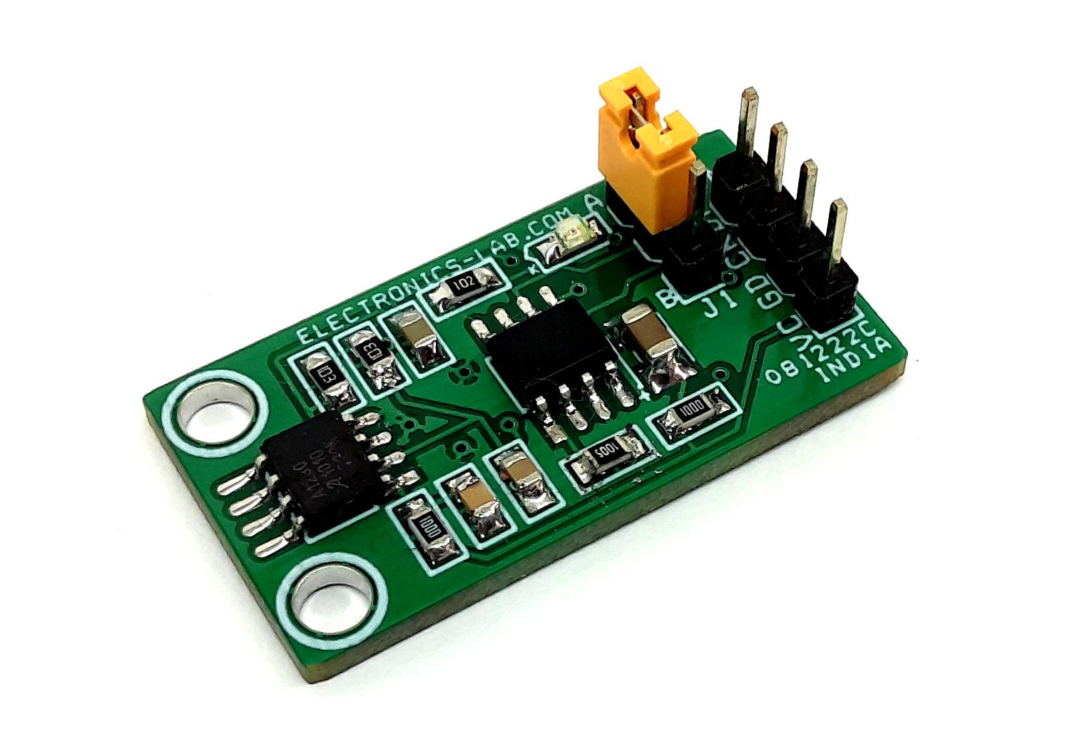
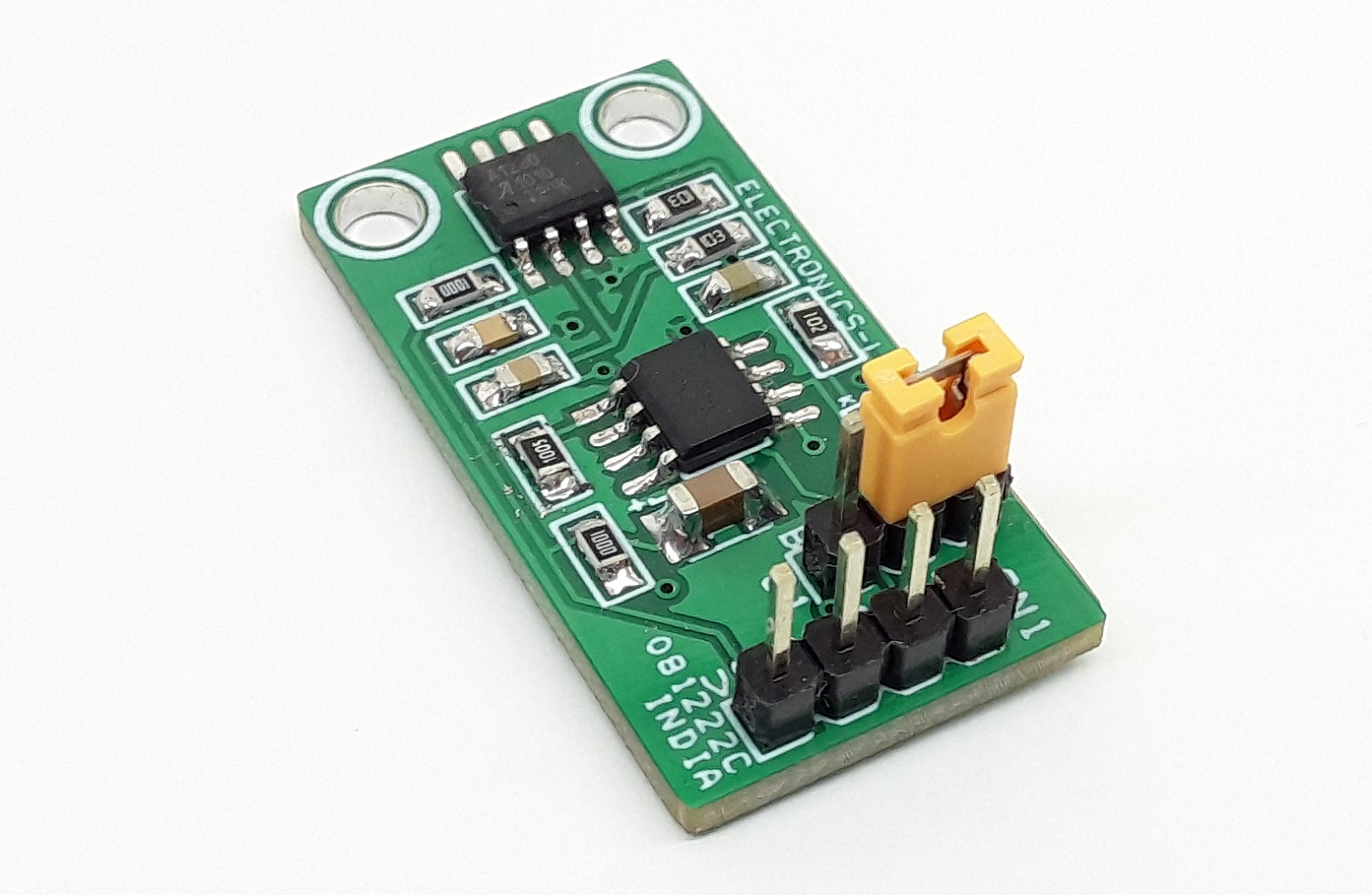
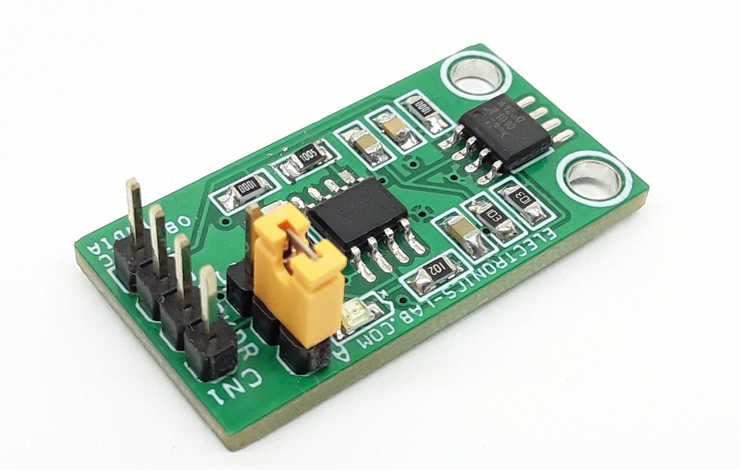
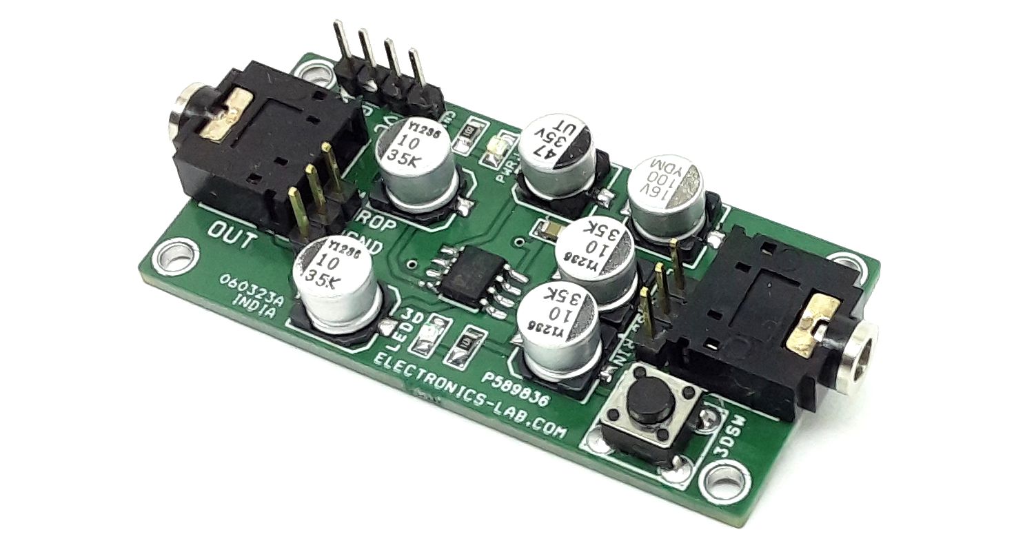
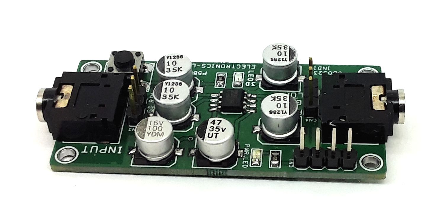
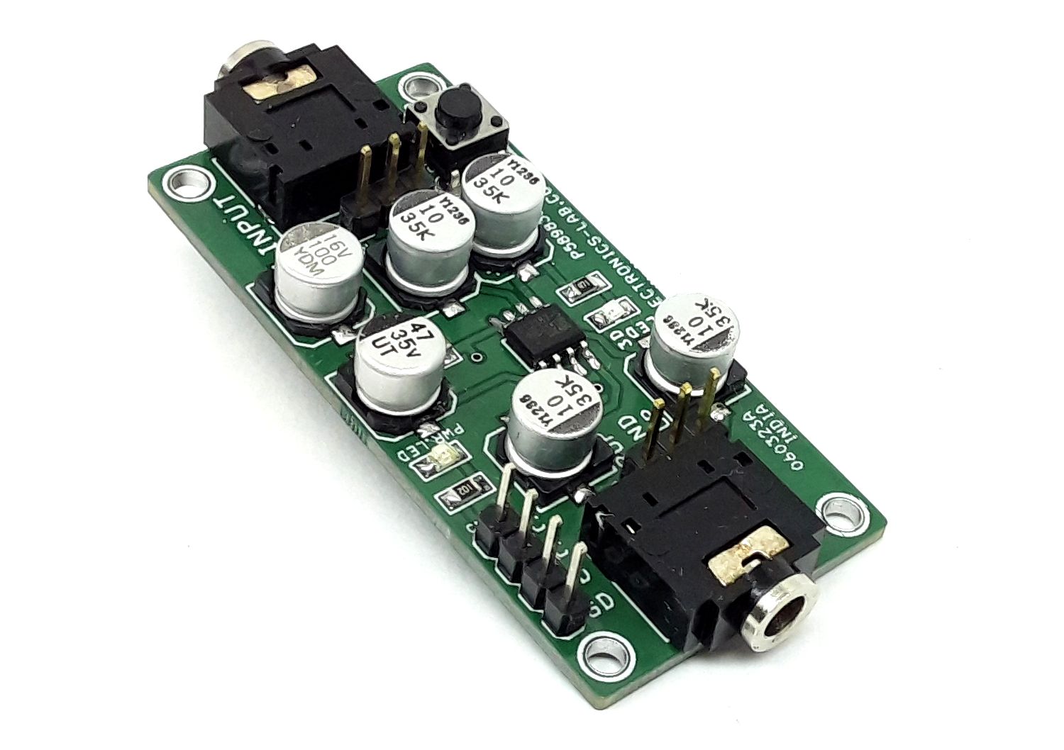
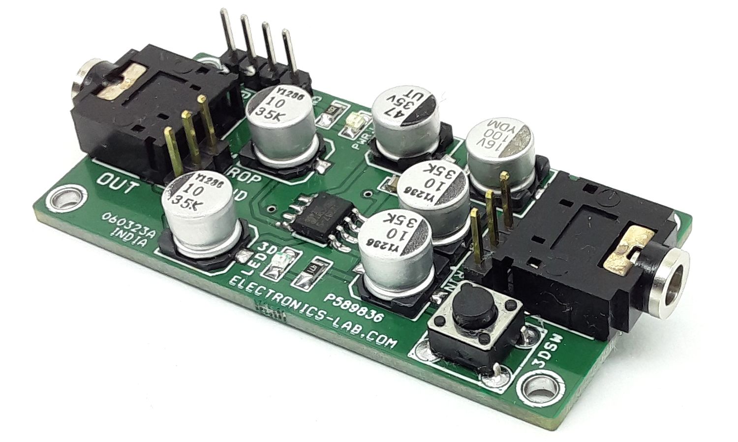
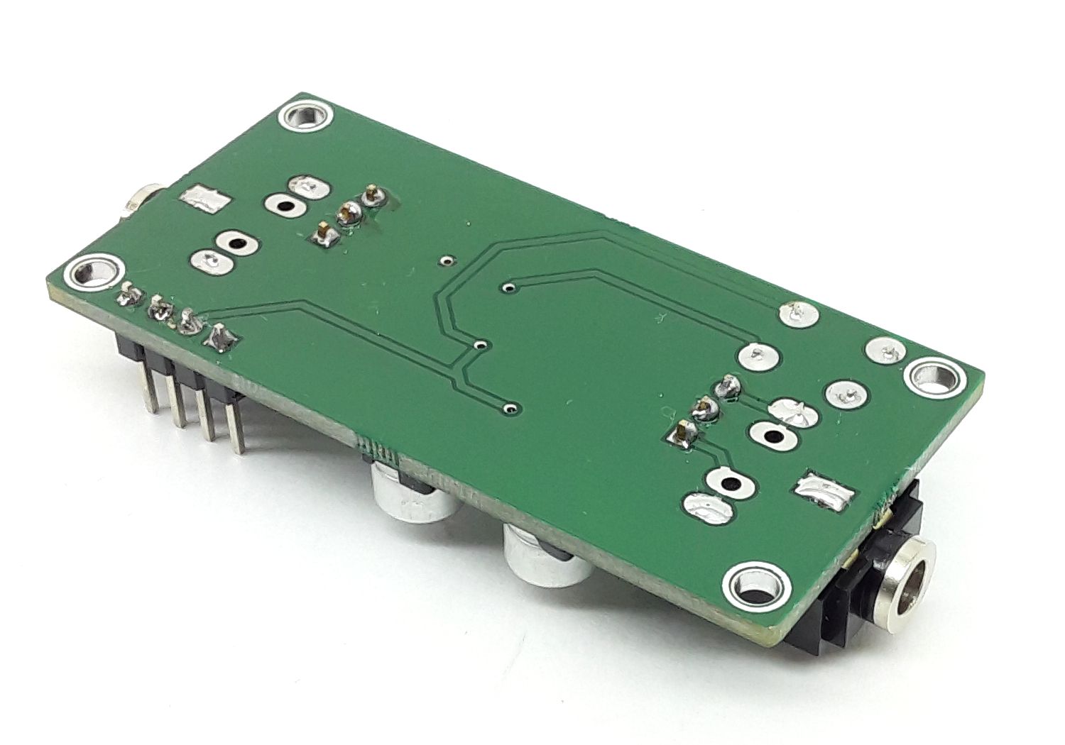
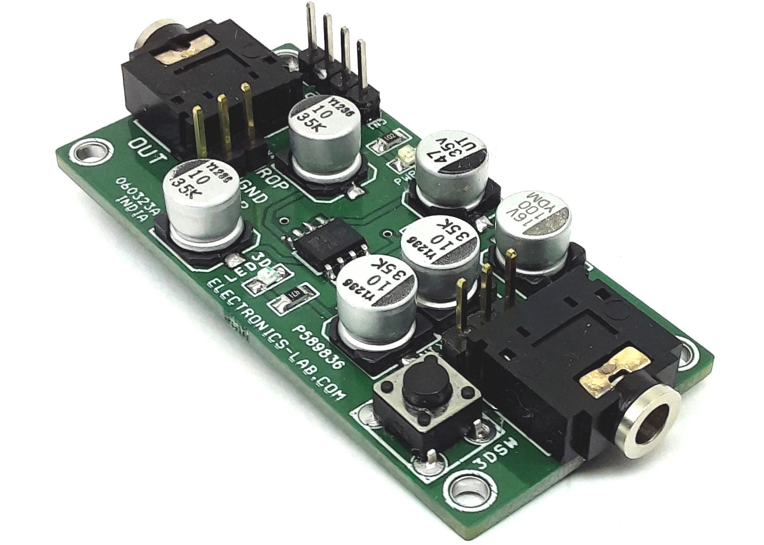
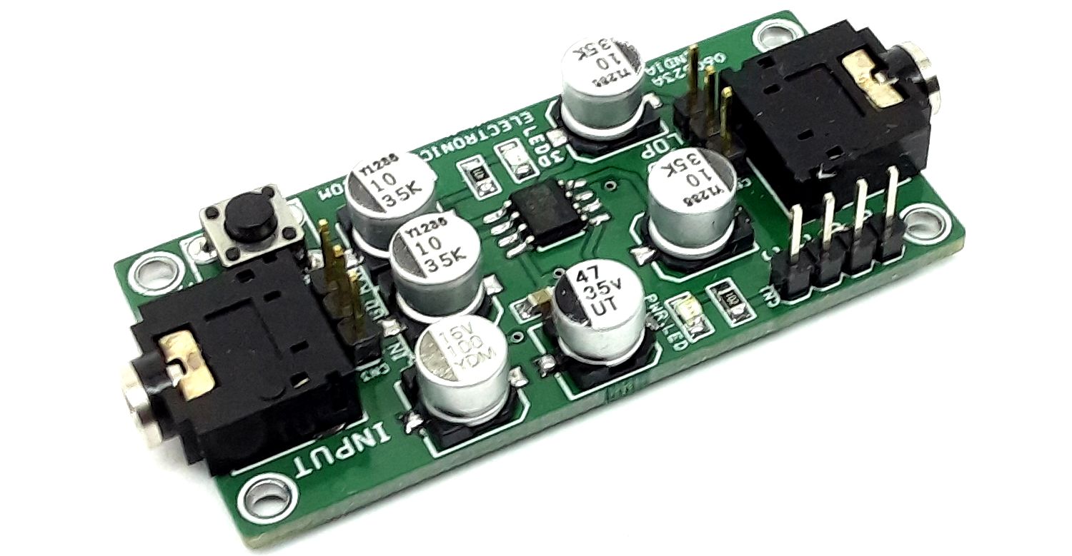
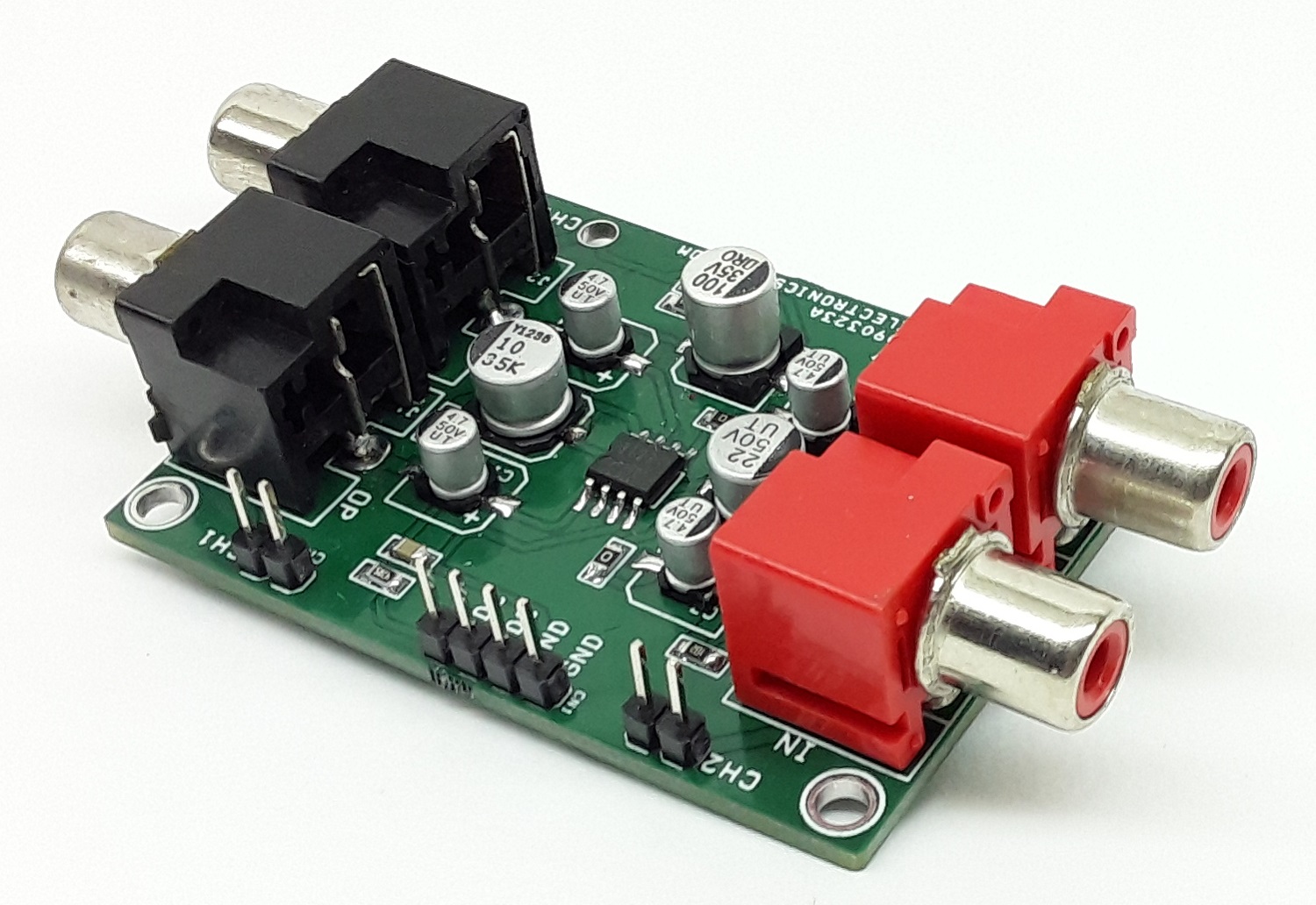
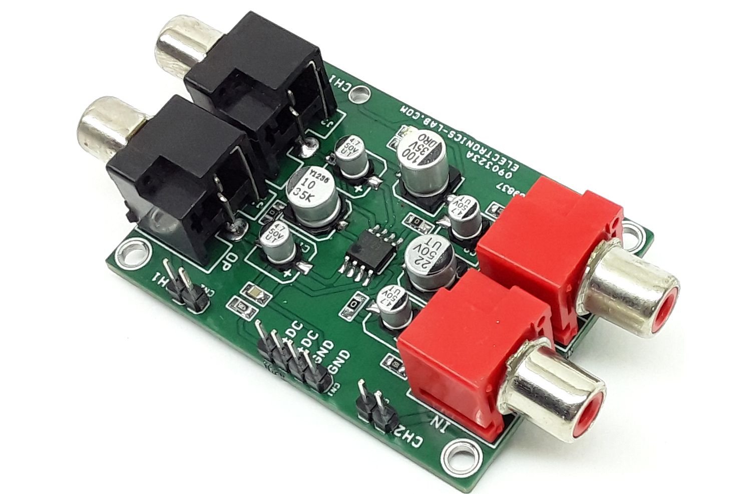
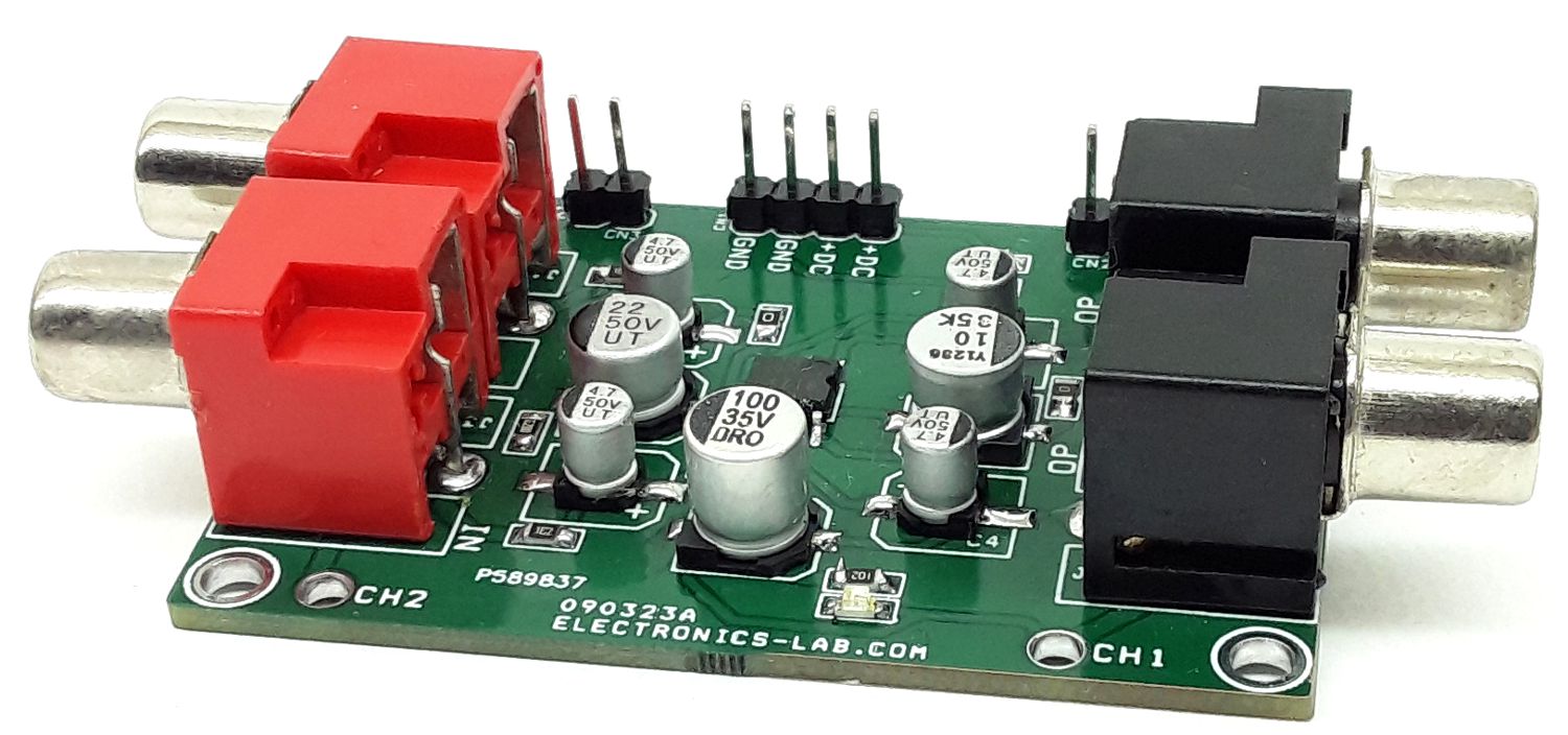
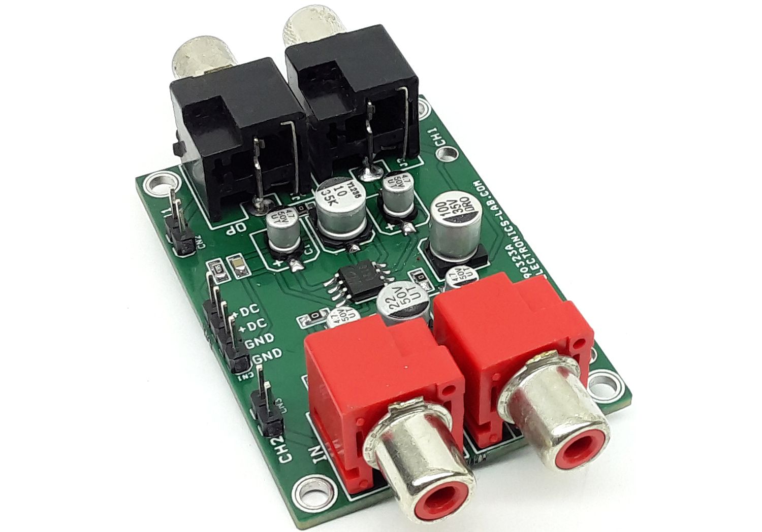
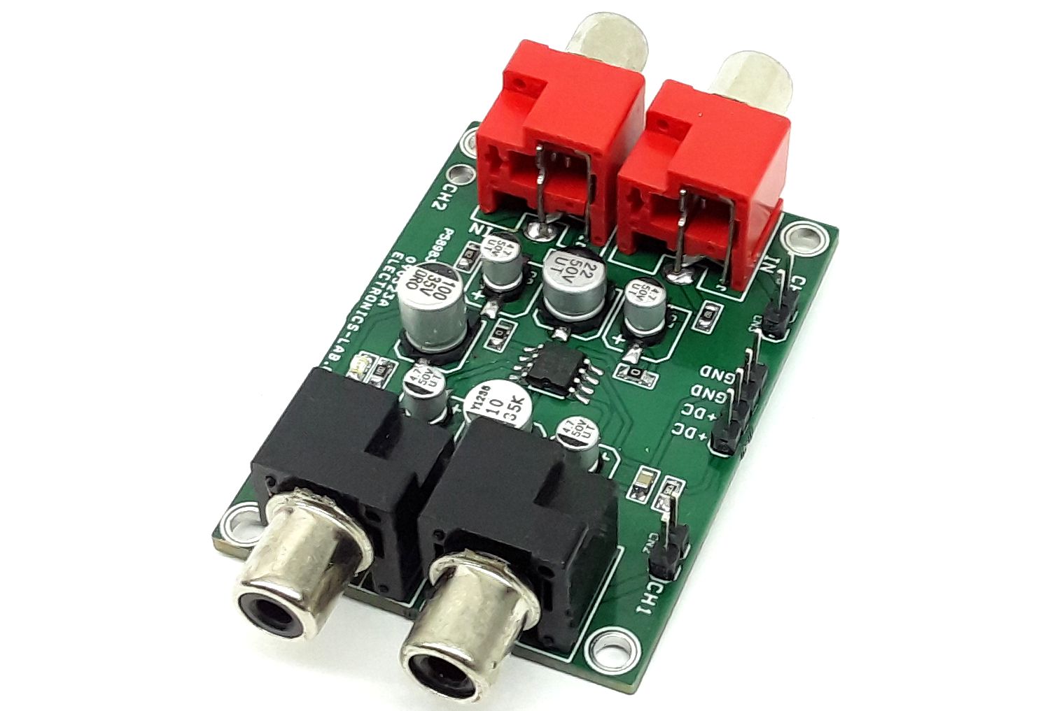
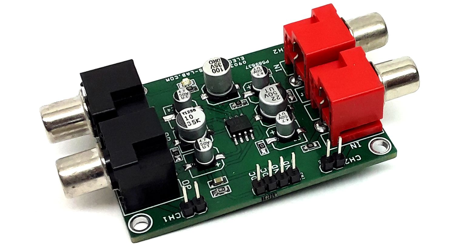
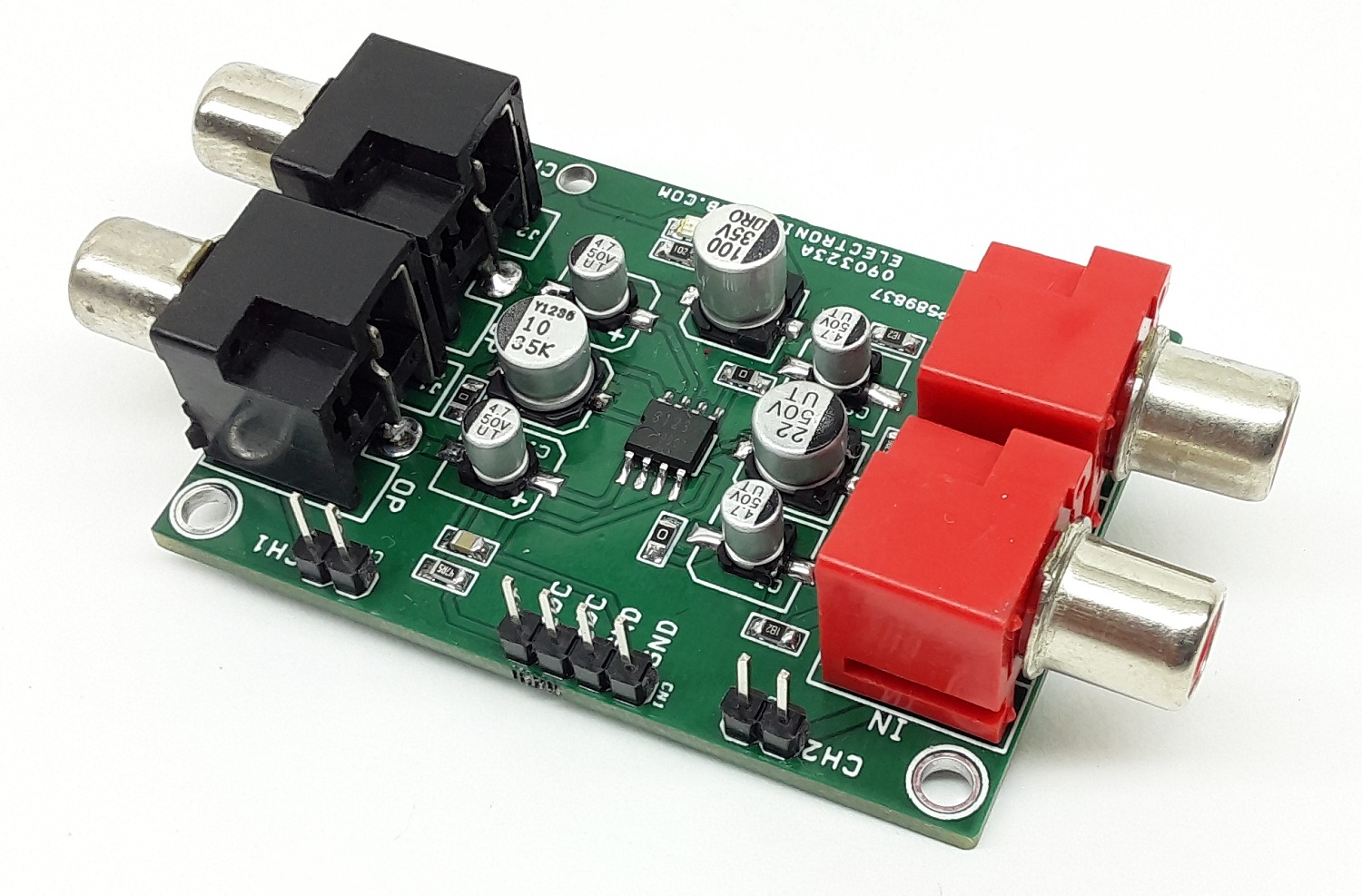
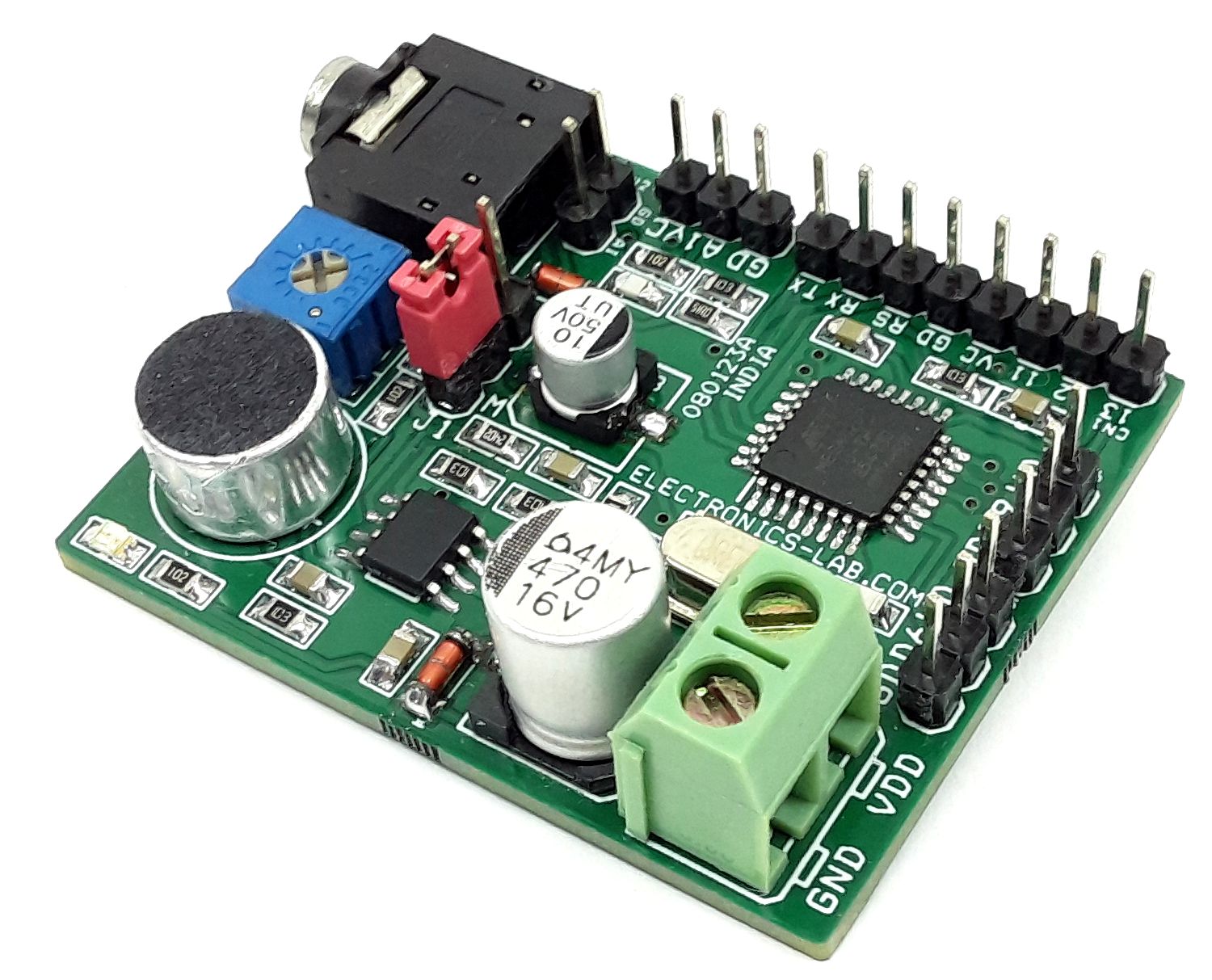
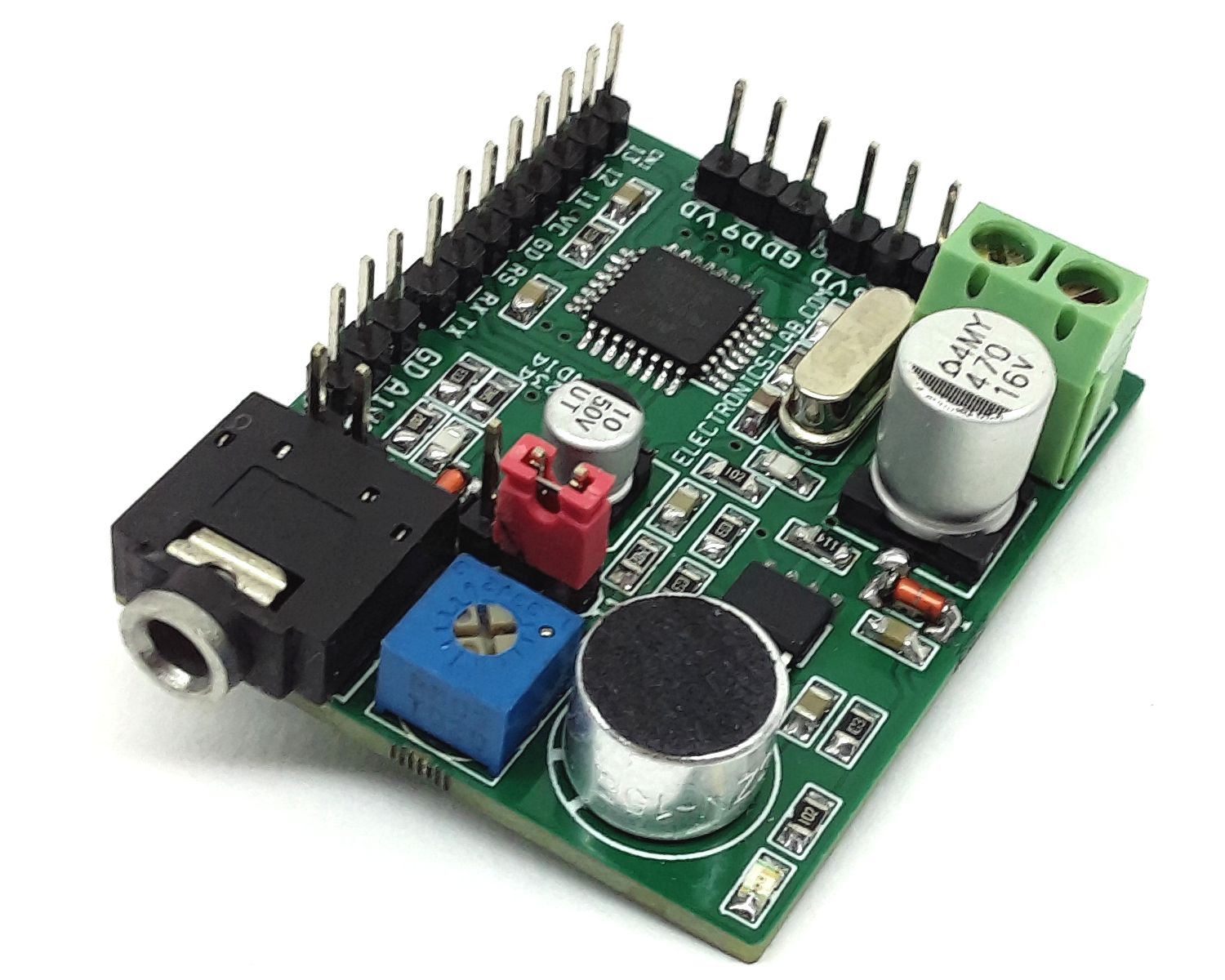
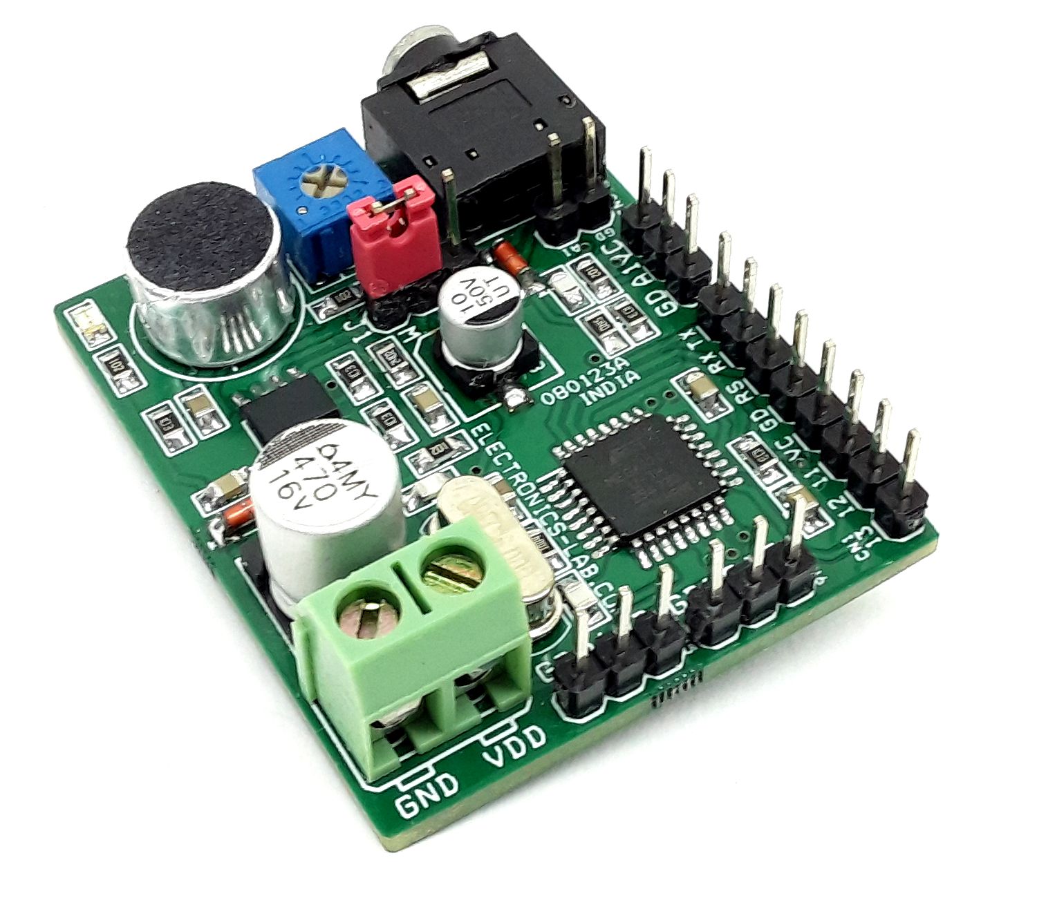
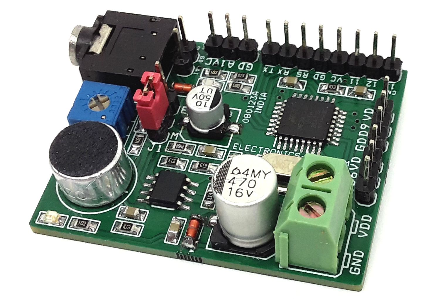
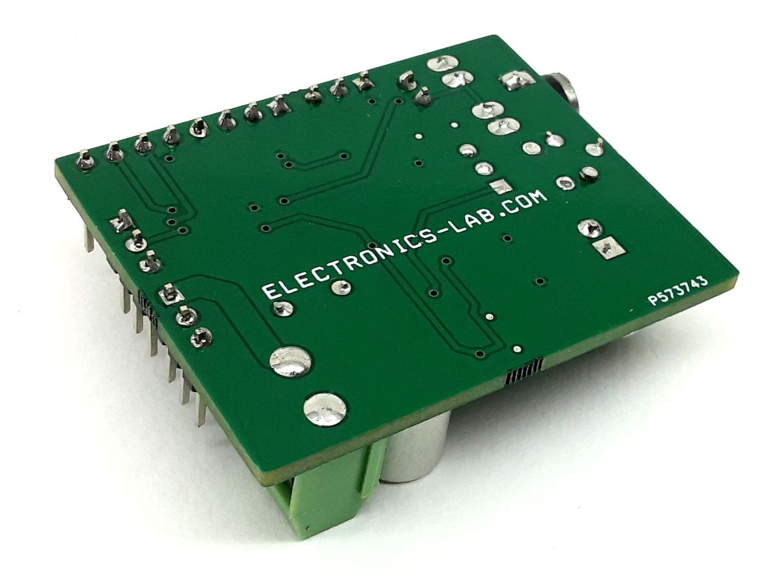
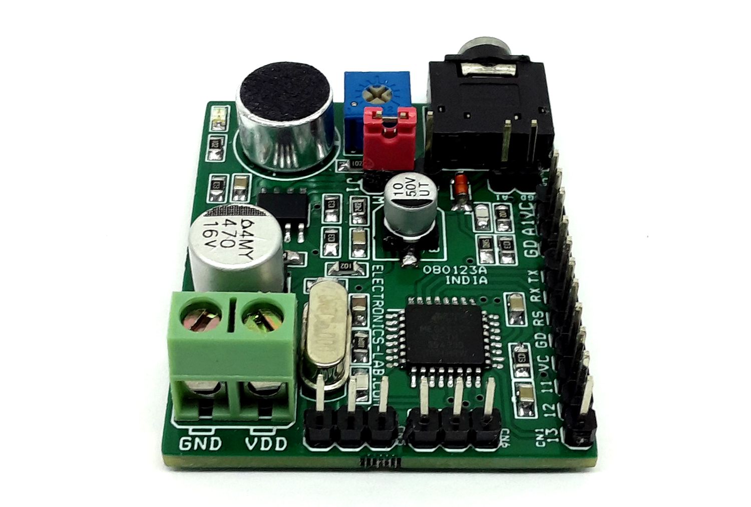
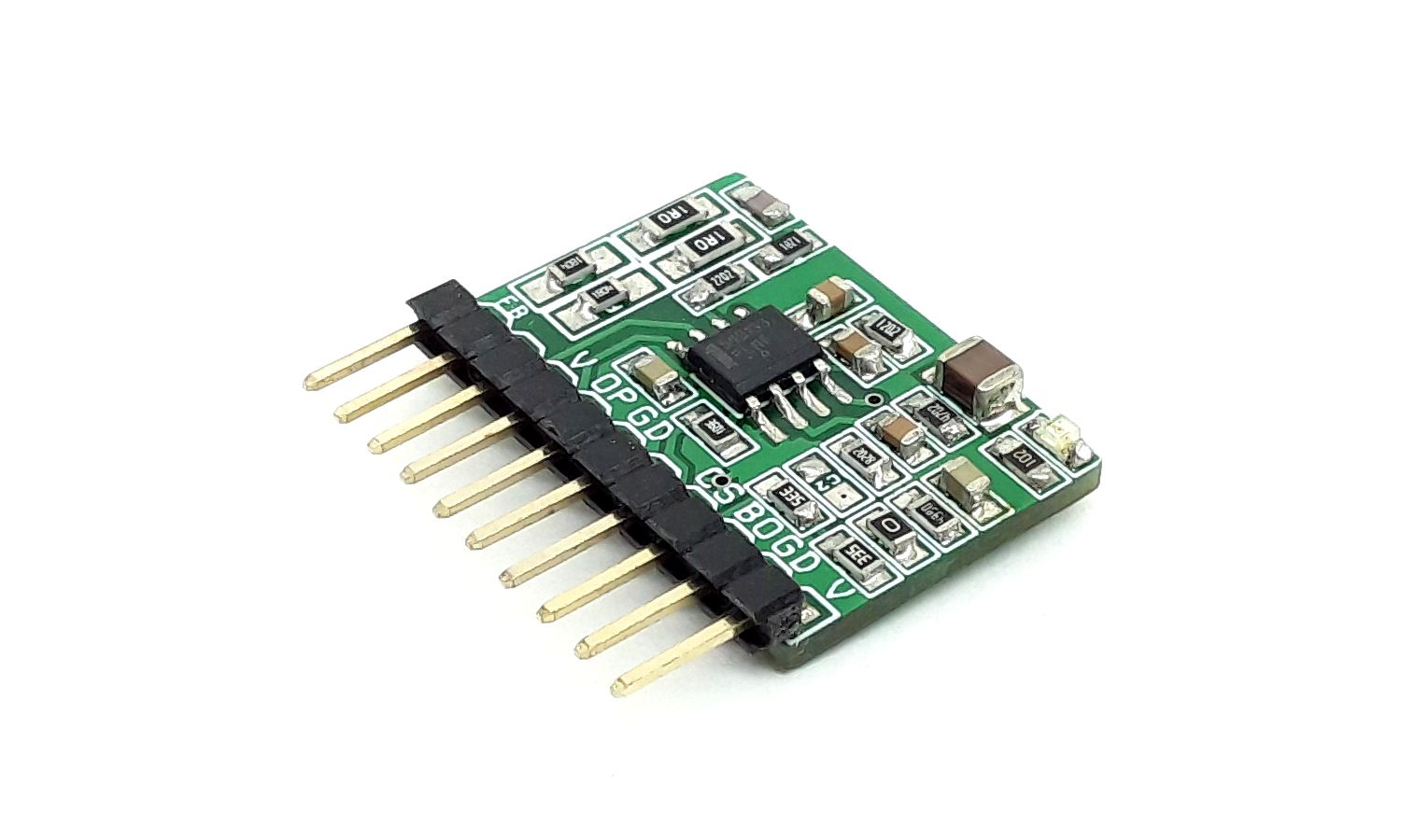
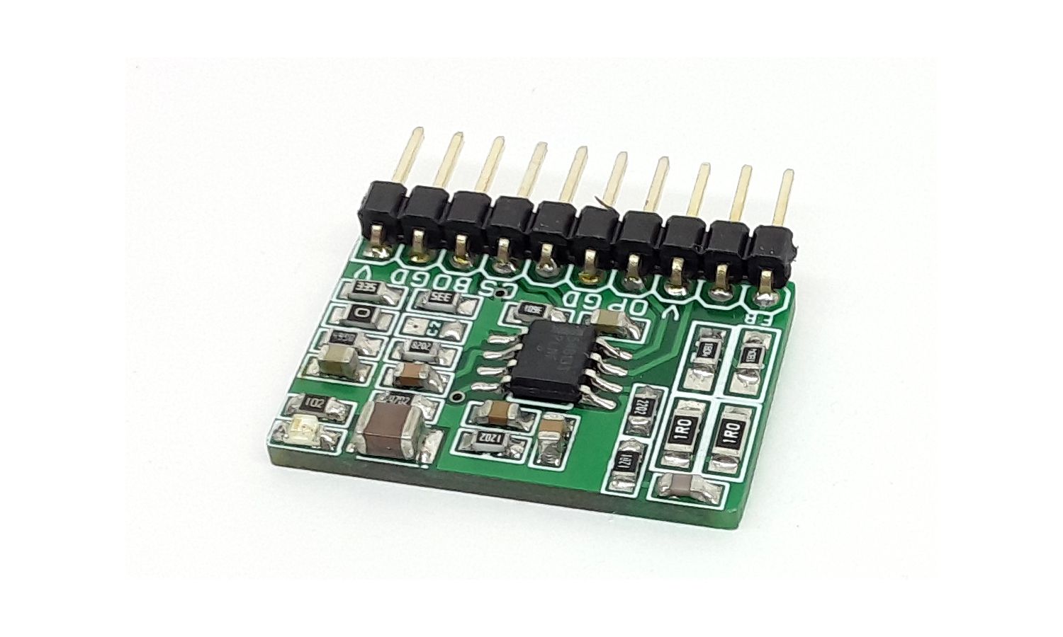
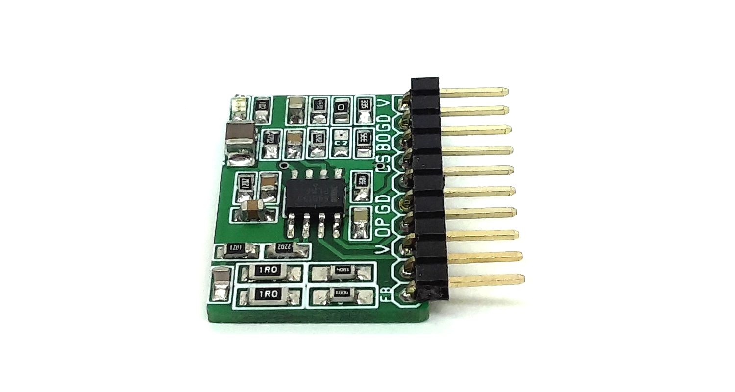
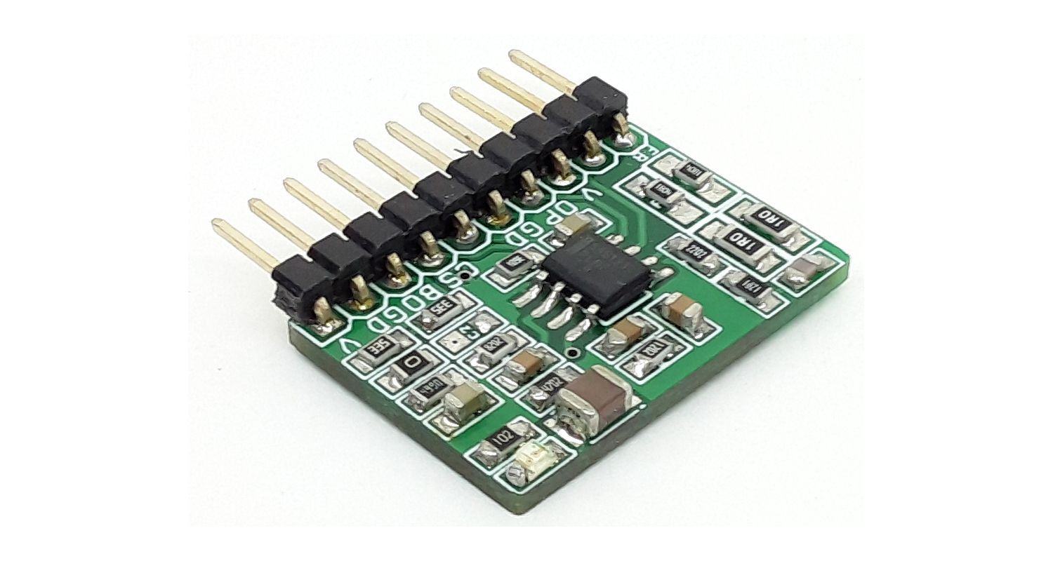
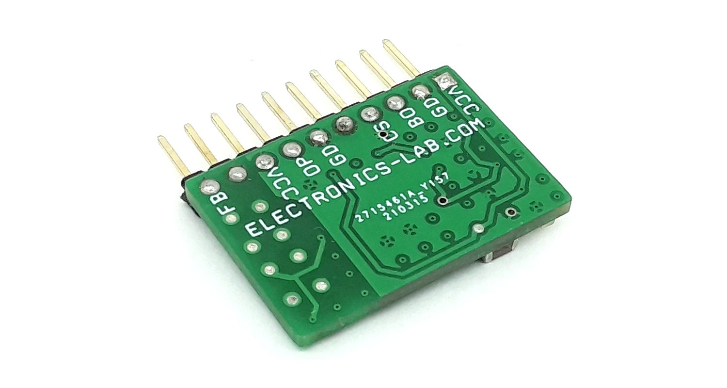
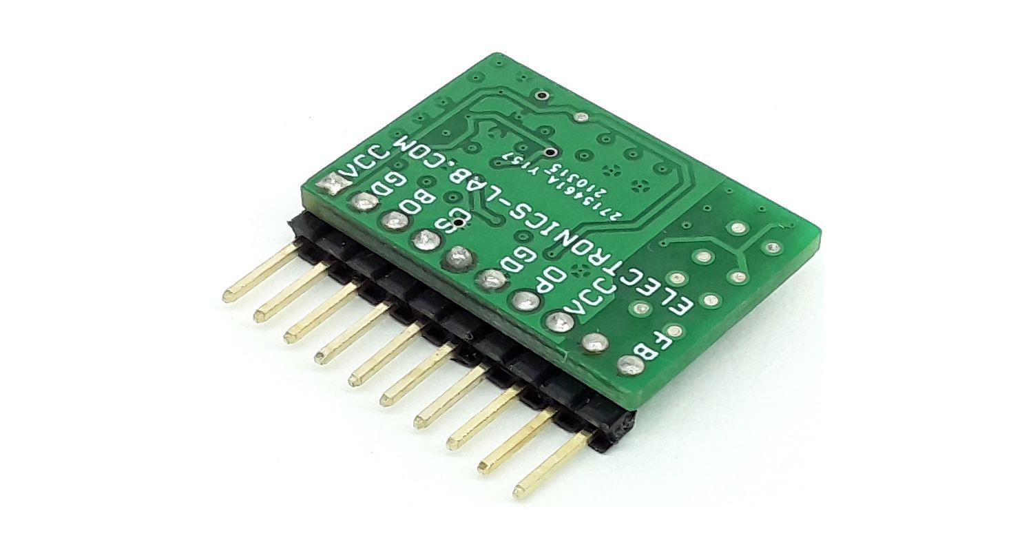
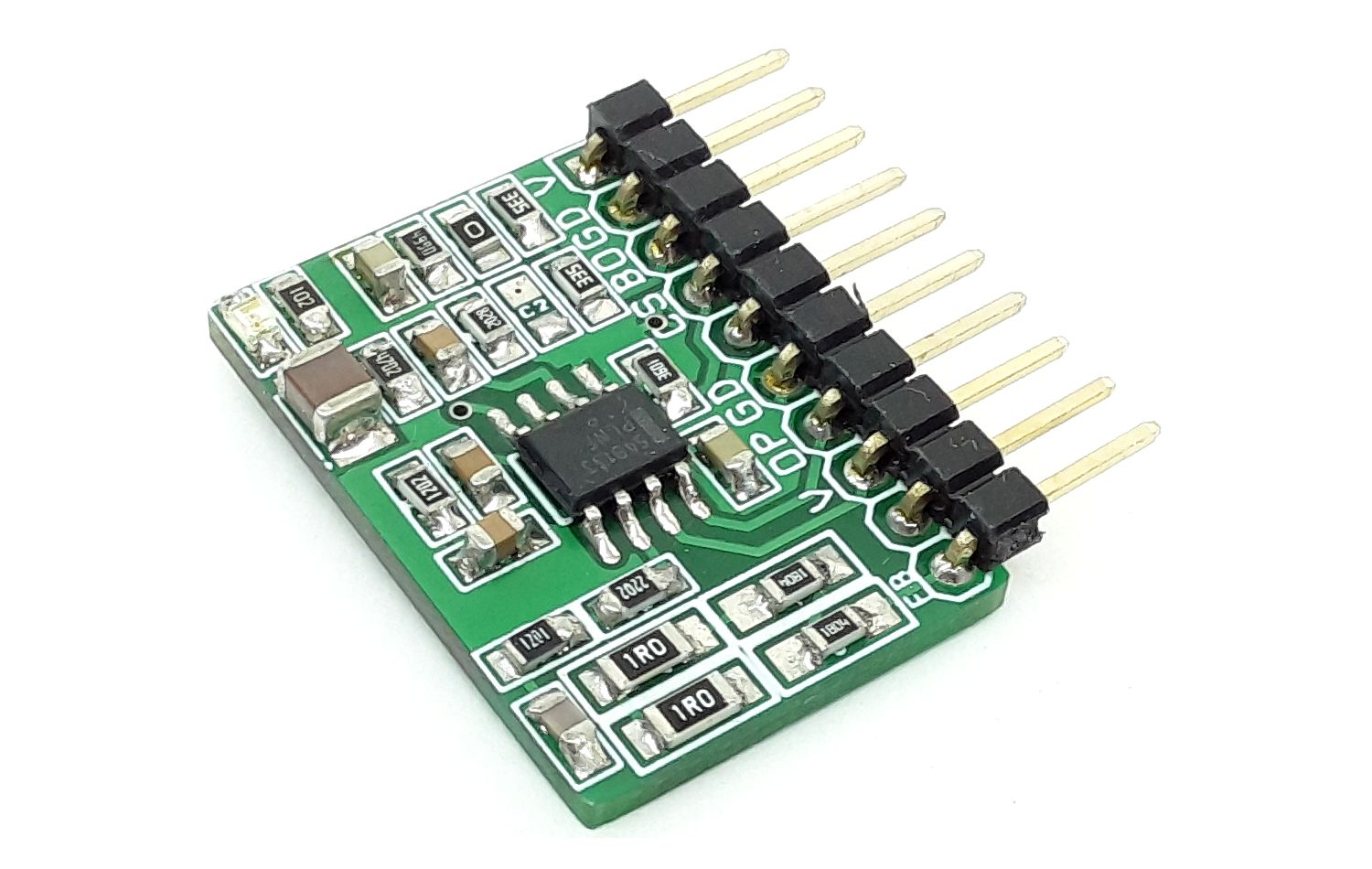
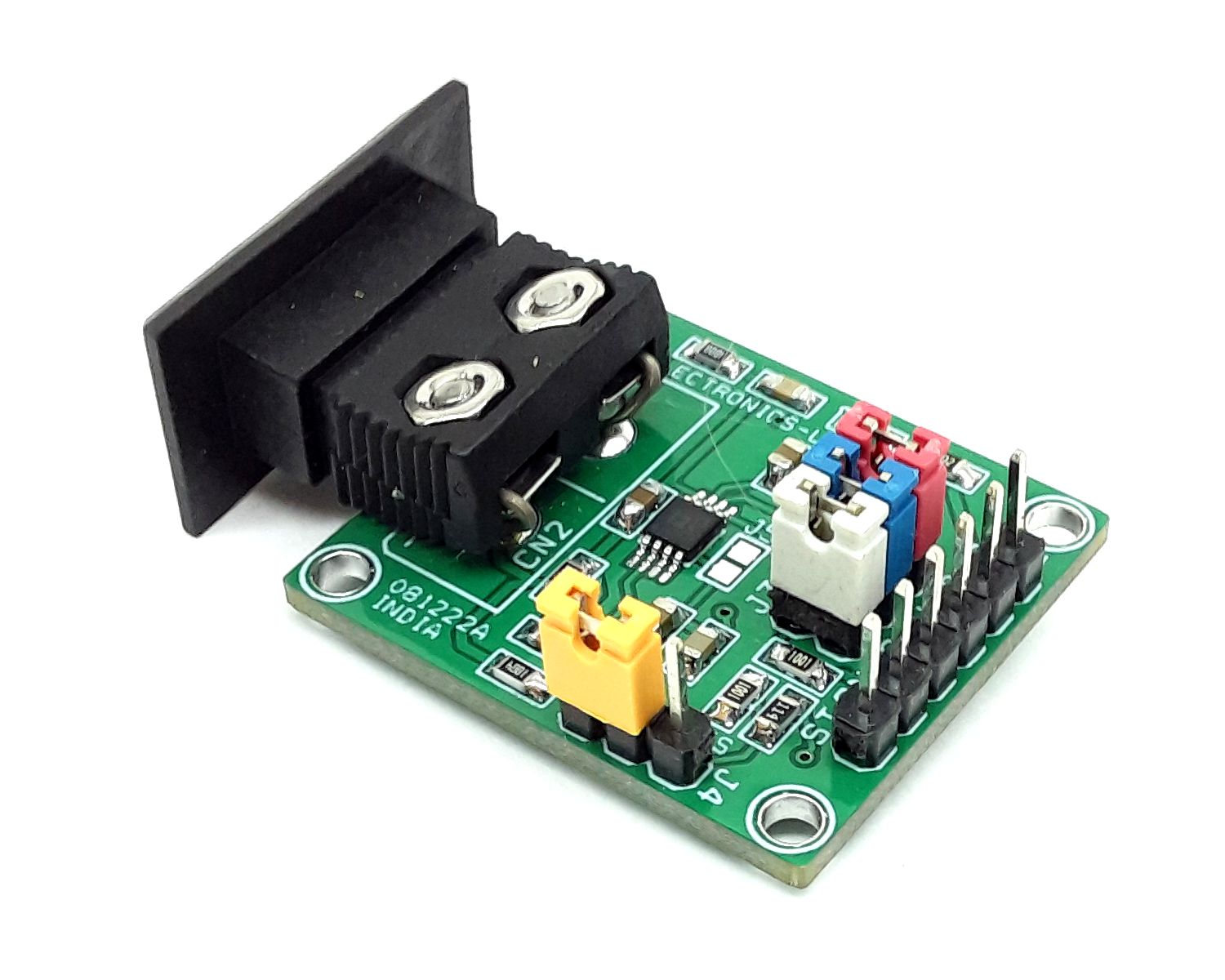
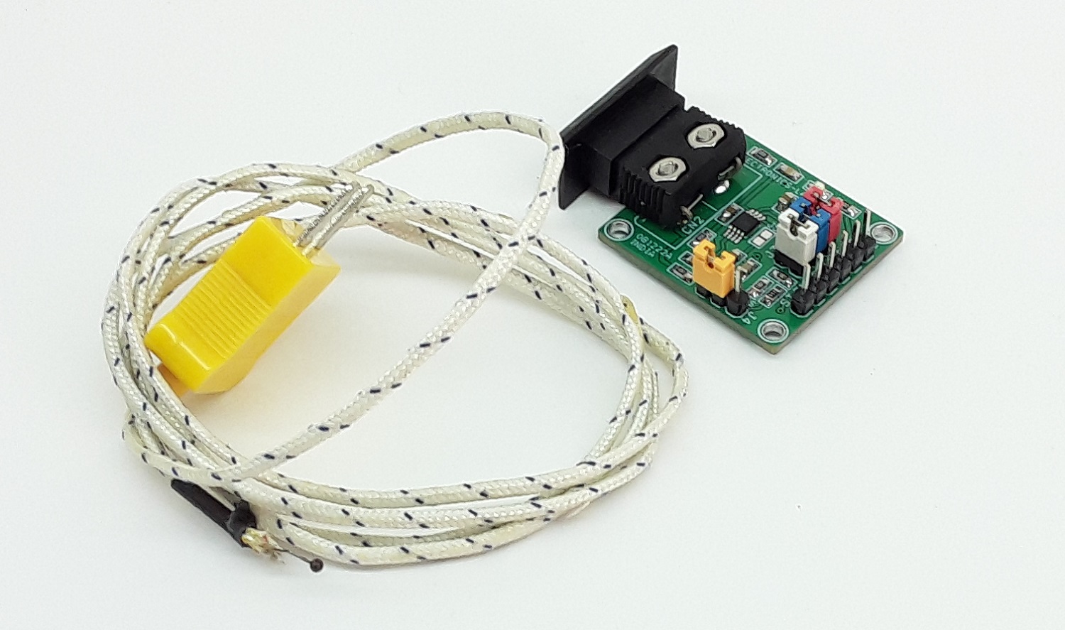
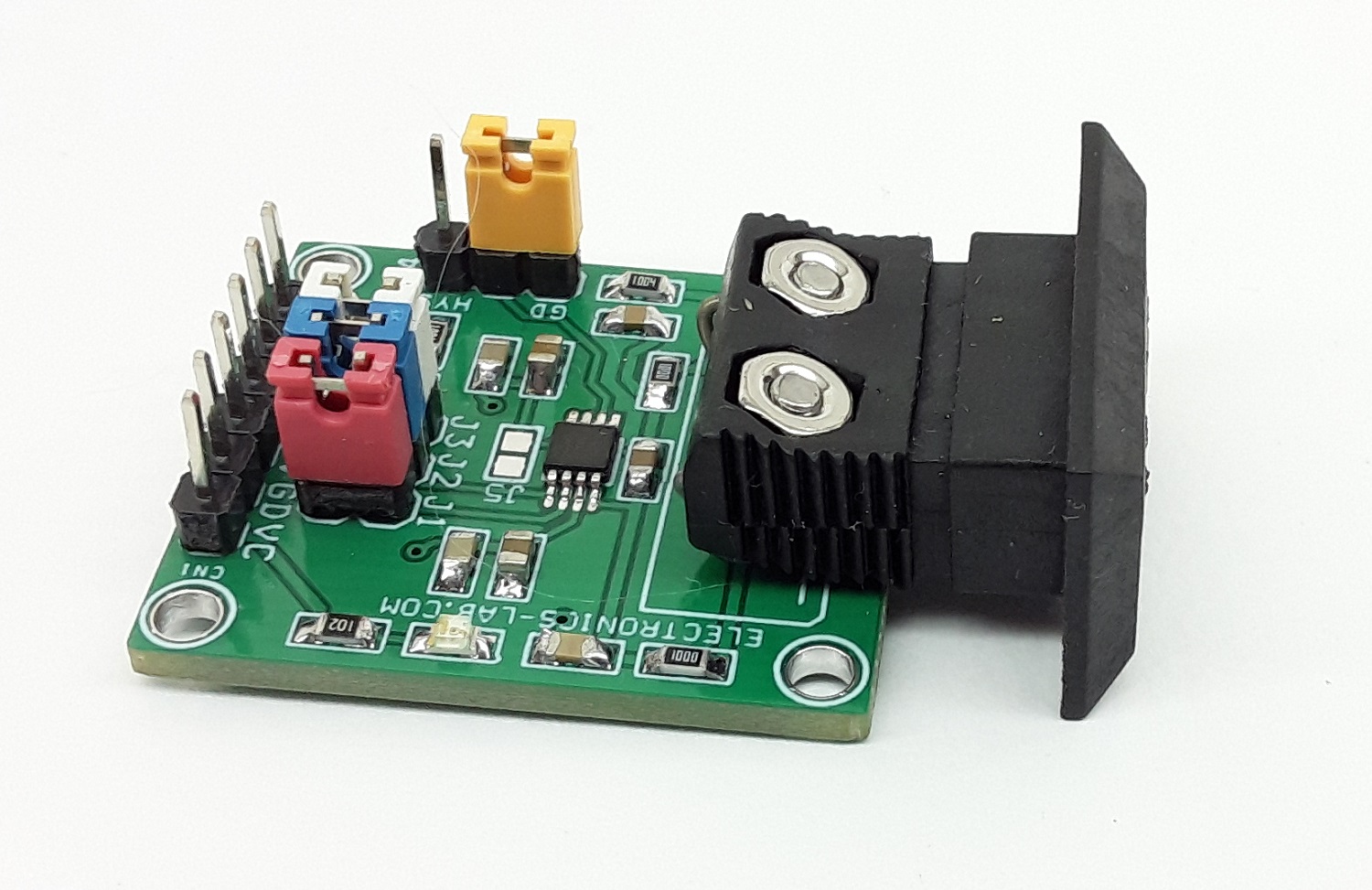
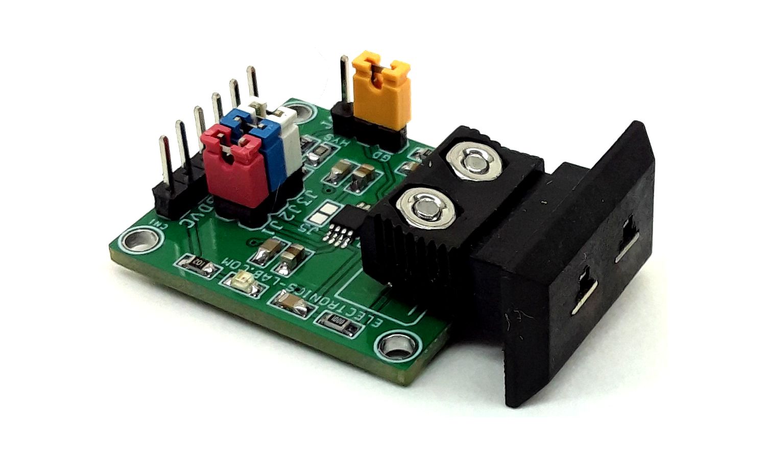
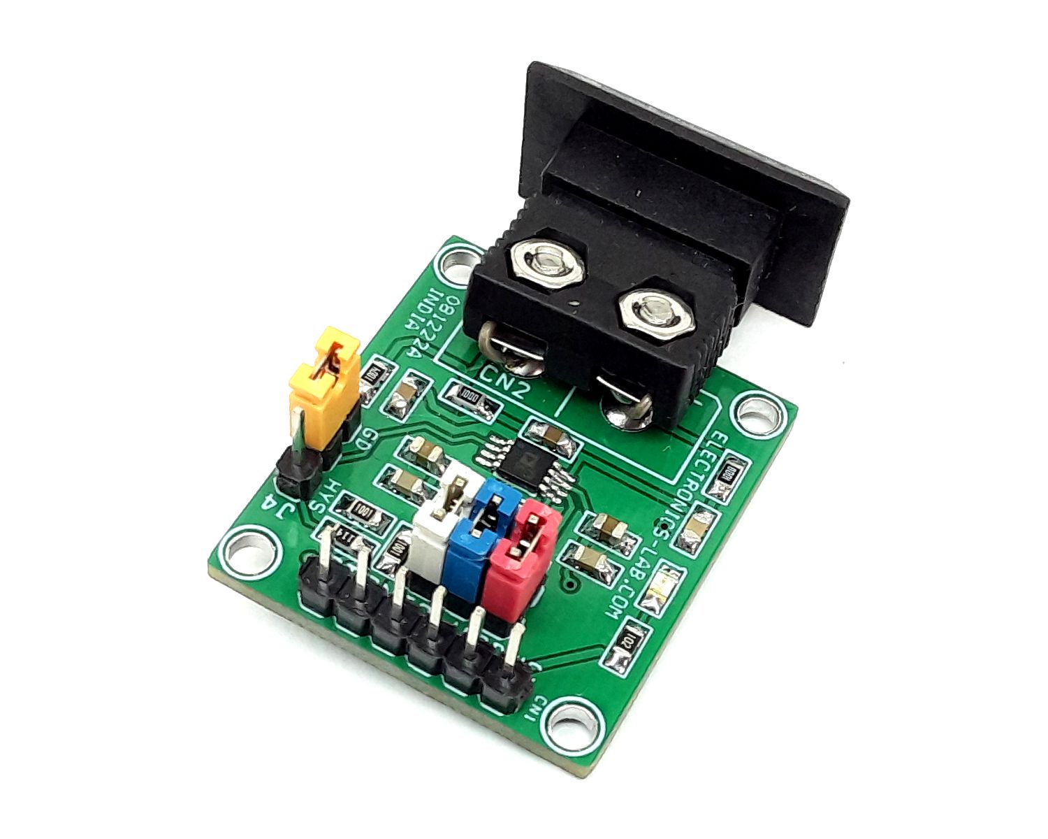
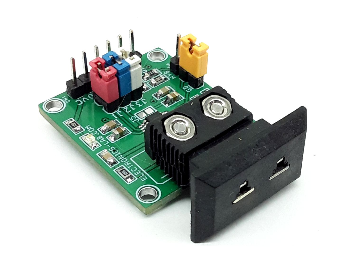
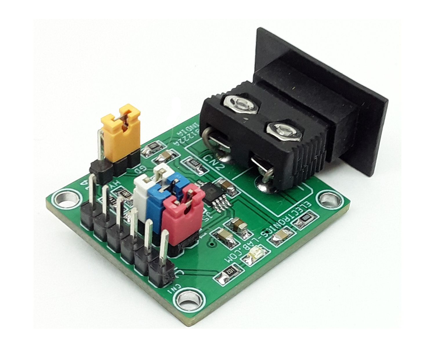
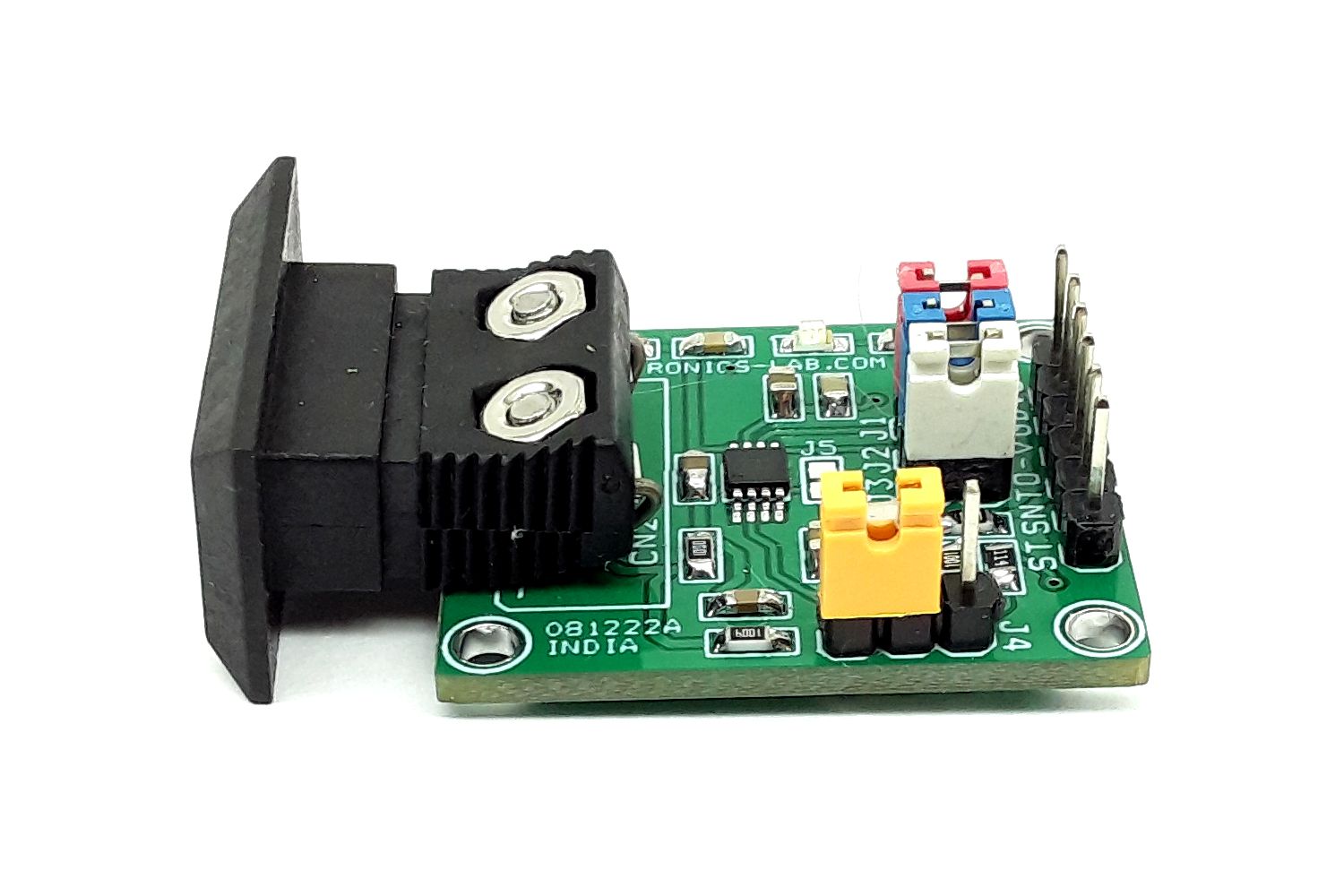
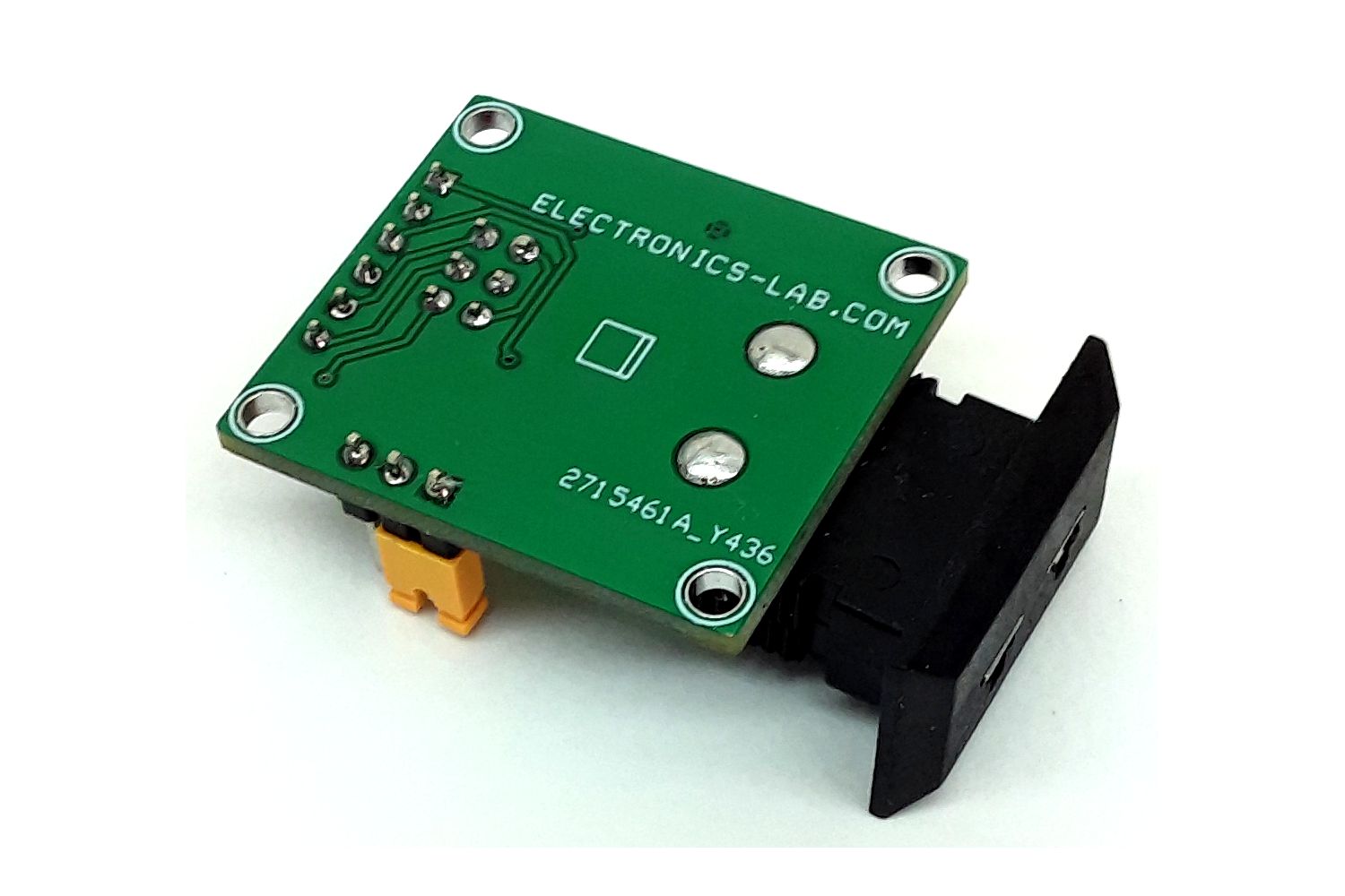
Photos