Nvidia has brought IGX edge AI developer kit for industrial applications

Nvidia IGX Orin developer kit

As edge computing has witnessed massive adoption from enterprises to bring digital transformation and expand their value proposition, they need to get their hands on industrial-grade edge development platforms. Nvidia has introduced the IGX Orin developer kit that combines enterprise-grade hardware, software, and all the necessary tools for application development leveraging edge artificial intelligence.

The Nvidia IGX Orin developer kit is designed to deliver the performance of 275 tera operations per second. The platform also includes an Nvidia Connect-7 smart network interface card with a claimed networking speed of 200 gigabits per second. Inside the IGX Orin module is a 12-core Arm processor with Ampere 1024 Cuda and 64 Tensor GPU.

The IGX Orin integrates a safety microcontroller unit that can program additional safety functions into the IGX software stack. This microcontroller unit can be programmed through software extensions and deliver advanced safety features in autonomous environments.

The core of the IGX stack includes several software components, such as a Linux board support package, drivers for supported input/output (IO) devices, NVIDIA AI inference and acceleration libraries, and reference applications. These components are essential for the functioning of the IGX hardware and provide the necessary support for various input/output (IO) devices.

Nvidia IGX Orin developer kit image

Additionally, the core stack is designed to be flexible and customizable. Customer-specific software components and applications can be added to the core stack to meet specific customer needs. This allows customers to tailor the IGX stack to their specific use cases and requirements.

The Nvidia IGX Orin developer board will be equipped with extra components and software to facilitate remote system management, software updates, and secure booting. These components will include a board management controller (BMC) and a software stack to enable remote system management and software updates, as well as a secure boot controller to ensure system integrity during the boot process by providing an external root of trust.

Some embedded manufacturers include ADLINK, Advantech, Dedicated Computing, Kontron, Leadtek, MBX, Onyx, Portwell, Prodrive Technologies, and YUAN, who will showcase their IGX Orin design to serve the industrial and medical sector. The developer kit is currently available on PNY Technologies and Arrow Electronics.

AAEON Announce the World’s First Fanless Mini PC with Intel Core i3 Processor N-series

UP Squared Pro 7000 Edge combines the reliability of a fanless design with the power of Intel® Core™ i3 Processor N-series, Atom® Processor X Series, and Intel® Processor N-series platforms.

Converting the ingenuity of the UP Squared Pro 7000 board to its edge system range, AAEON’s UP Squared Pro 7000 Edge is the first mini PC to harness the power of Intel® Core™ i3 Processor N-series, Atom® Processor X Series, and Intel® Processor N-series processors in a fanless chassis.

The first fanless mini PC to utilize the processor platforms, the UP Squared Pro 7000 Edge provides developers with the same performance boost as its board counterpart, but with a more convenient route to market. The device’s heatsink offers effective heat dissipation without the obvious drawbacks of a fan-based cooling system, opening the door to deployment in more settings, such as smart manufacturing and healthcare.

Key Features:

  • Alder Lake-N processor platform
  • Removable heatsink for easy 5G, Wi-Fi 6, and AI expansion module installation
  • 2.5GbE x 2, USB 3.2 Gen 2 x 3, RS-232/422/485 x 2, 40-pin GPIO
  • 3 simultaneous 4K displays

A multipurpose design, the UP Squared Pro 7000 Edge’s heatsink contains a removable section for users to access the PC’s expansion slots. This makes the installation of 5G, Wi-Fi 6, and AI expansion modules much more efficient and convenient. In keeping with the UP system range’s previous iterations, the device’s rear I/O also houses a 40-Pin GPIO for further expansion.

The UP Squared Pro 7000 Edge presents improvements across its external I/O, with both LAN ports supporting 2.5GbE, compared to only one in the case of its predecessor. Further, a USB 3.2 Gen 2 Type-C port joins two USB 3.2 Gen 2 Type-A ports; while two COM ports supporting RS-232/422/485 have been added across all SKUs, a feature which until now had been limited to one COM port available only on SKUs powered by Intel Atom® CPUs.

For more information about the UP Squared Pro 7000 Edge, please visit our product page or contact an AAEON representative directly.

9V @ 45mA Boost Converter Output with Input 2.1V to 5.5V

The project shown here is a boost converter that provides 9V DC output from 2.1V to 5.5V input. It is a good choice for battery-operated devices where the converter can be connected to 2x 1.5V, 3 x 1.5V Battery, 1 x Li-ion, 2 x NICAD, 2 x NIMH, and provide 9V Output. The board is built using BD8158FVM chip and the pin configuration is the same as TO220 78xx LDO and the size is also the same. Output is very accurate and provides approx. 85% efficiency at an operating frequency of 1.2Mhz.

Features

  • Input 2.1V to 5.5V (2 X NIMH Battery, 2 X NICAD Battery, 1X Li-Ion Battery 3.6V, 2X AA/AAA battery)
  • 3 Pin Header Pitch 2.54MM for Output and Input (Pin Configuration same as TO220 LDO Such as LM7805)
  • Output 9V DC
  • Output Current 45mA
  • 85% Efficiency
  • Output Voltage +/-1%
  • Current Mode PWM System
  • Built-In Under-Voltage Lockout Protection Circuit
  • Built-In Over-Current Protection Circuit
  • Built-In Thermal Shutdown Circuit
  • PCB Dimensions 20.16 x 9.05mm

Protection Circuit (UVLO/TSD) UVLO (under-voltage lockout protection circuit) shuts down the circuit when the voltage is equal or lower than 1.8V. Thermal shutdown circuit shuts down IC’s operation at 175°C and recovers at 160°C.

Over-Current Protection Circuit (OCP) Current flowing to the power FET is detected by voltage at the CURRENT SENSE and the Over-Current protection operates at 3A. When the Over-Current protection activates, the switching is turned OFF and the SS pin capacity is discharged.

Soft-Start Circuit Since the output voltage rises gradually while restricting the current at the time of start-up, it is possible to prevent the output voltage overshoot or the inrush current.

Connections

CN1: Pin 1 = Input 2.1V to 5.5V, Pin 2 = GND, Pin 3 = Output 9V DC – 45mA

Schematic

Parts List

NOQNTYREF.DESCMANUFACTURERSUPPLIERSUPPLIER PART NO
11CN13 PIN MALE HEADER RIGHT ANGLE PITCH 2.54MMWURTHDIGIKEY
21C1100PF/25V CERAMIC SMD SIZE 0805MURATA/YAGEODIGIKEY
31C23.3nF/25V CERAMIC SMD SIZE 0805MURATA/YAGEODIGIKEY
41C310nF/25V CERAMIC SMD SIZE 0805MURATA/YAGEODIGIKEY
51C410uF/25V CERAMIC SMD SIZE 1206MURATA/YAGEODIGIKEY
61D1SS34 SMD FAST SWITCHING DIODETAIWAN SEMIDIGIKEY1801-SS34TR-ND
71L110uH/SMD 8MM EATONDIGIKEY283-SDCH1V6028-100M-RCT-ND
81R15.1K/1% SMD SIZE 0805MURATA/YAGEODIGIKEY
91R2110K/1% SMD SIZE 0805MURATA/YAGEODIGIKEY
101R318K/1% SMD SIZE 0805MURATA/YAGEODIGIKEY
111U1BD8158FVM-TRROHMDIGIKEYBD8158FVMCT-ND
121C510uF/25V CERAMIC SMD SIZE 0805MURATA/YAGEODIGIKEY

Connections

Gerber View

Photos

Video

BD8158FVM Datasheet

3.3V-5A Output DC-DC Converter with 10 to 24V Input

The project published here is a synchronous step-down DC/DC converter based on the RT7258 chip. The chip has integrated high-side internal power MOSFET and gate driver for a low-side external power MOSFET. The board delivers 3.3V DC – 5A output current from 10V to 24V input supply. The RT7258‘s current mode architecture allows the transient response to be optimized over a wide input voltage and load range. Cycle-by-cycle current limit provides protection against shorted outputs and softy-start eliminates input current surge during start-up.

Features

  • Supply 10V to 24V DC
  • Output 3.3V DC
  • Load Current 5Amps
  • Current Mode Control
  • Switching Frequency 600Khz
  • Up to 90% Efficiency
  • Cycle-by-cycle Current Limit
  • Input Under Voltage Lockout
  • Output Under Voltage Protection
  • Thermal Shutdown Protection, Threshold 150°C
  • Output Power LED
  • 4 x 2.5mm Mounting Holes
  • PCB Dimensions 51.44 x 24.13 mm

Soft-Start (SS): An internal current source charges an internal capacitor to build the soft-start ramp voltage (VSS). The VFB voltage will track the internal ramp voltage during the soft-start interval. The typical soft-start time is 2ms.

Over Temperature Protection

The RT7258 features Over Temperature Protection (OTP) circuitry to prevent overheating due to excessive power dissipation. The OTP will shut down the switching operation when the junction temperature exceeds 150°C. Once the junction temperature cools down by approximately 20°C, the converter will resume operation. To maintain continuous operation, the maximum junction temperature should be lower than 125°C.

Connections

  • CN1: Pin 1 = 10V to 24V DC Input, Pin 2 = GND
  • CN2: Optional Connector for TO220 MOSFET
  • CN3: Pin 1 = 3.3V / 5Amps Output, Pin 2 = GND
  • D1: Output Power LED

Schematic

Parts List

NO.QNTY.REF.DESC.MANUFACTURERSUPPLIERSUPPLIER'S PART NO
12CN1,CN32 PIN SCREW TERMINAL PITCH 5.08MMPHOENIXDIGIKEY277-1247-ND
21CN2DNP
35C1,C3,C4,C5,C622uF/25V CERAMIC SMD SIZE 0805YAGEO/MURATADIGIKEY
42C2,C71uF/25V CERAMIC SMD SIZE 0805YAGEO/MURATADIGIKEY
51D1LED RED SMD SIZE 0805OSRAMDIGIKEY475-1278-1-ND
61L12.2uH/10A SMD OR THT 12X12MMCHILISIN ELECTRDIGIKEY553-BPRR001010512R2TA0TR-ND
71Q1FDD8876CTON SEMIDIGIKEYFDD8876CT-ND
81R162K 1% SMD SIZE 0805YAGEO/MURATADIGIKEY
91R21K 5% SMD SIZE 0805YAGEO/MURATADIGIKEY
101R320K 1% SMD SIZE 0805YAGEO/MURATADIGIKEY
111R449.9K 1% SMD SIZE 0805YAGEO/MURATADIGIKEY
121R510.2K 1% SMD SIZE 0805YAGEO/MURATADIGIKEY
131U1RT7258 SOIC8RICHTEK USA INCDIGIKEY1028-1214-1-ND

Connections

Gerber View

Photos

Video

RT7258 Datasheet

21-Watt Universal AC LED Driver with Accurate Average-Mode Constant Current Control

The project presented here is an average current mode control LED driver operating in a constant off-time mode. The project consists of a bridge rectifier followed by a buck converter operating with a fixed off-time of 20µs. The circuit provides accuracy, and line and load regulation of the LED current. The output LED current accuracy is +/-4%. The project is built using HV9961 chip which is equipped with a current limit comparator for hiccup-mode output short circuit protection. A PWM dimming input is provided that accepts an external control of a TTL-compatible signal. Connect the PWMD terminal to the VDD terminal using the jumper provided to enable the LED driver.

HIGH VOLTAGE: Dangerous voltage exists until the power is off. Wait at least 1 minute after the input power is disconnected before touching the board and discharging HV capacitors.

Features

  • Supply 90V to 265V AC 50Hz/60Hz
  • Output 20 to 60V, 350mA
  • Full Load Efficiency Up to 92%
  • Switching Frequency 38Khz
  • Fast Average Current Control
  • PWM Dimming Input (Jumper J1)
  • Output Short-Circuit Protection with Skip Mode
  • PCB Dimensions 74.93 x 40.64mm
  • 4 x 4MM Mounting Holes

Connections and Other Details

  • CN1: Pin 1 = AC Live Input, Pin 2 = AC Neutral Input (90V to 265V AC Input)
  • CN2: Pin 1 = DC 20V to 60V DC @ 350mA Output (+LED), Pin 2 = -LED
  • Jumper J1: Pin 1 = VDD, Pin 2 = PWM In/Enable, Pin 3 = GND, Connect to VDD = Enable, Use as PWM input for Dimmer Function
Typical LED Cluster

PWM Dimming

The circuit is capable of being PWM dimmed by applying a square wave TTL compatible signal between PWMD and GND terminals of Jumper J1. However, since there is no galvanic isolation on the board, care must be taken to prevent damage to the PWM dimming source and/or the circuit.

The LED driver features tight regulation of the LED current within a few milliamps over the entire range of the input AC line and the output LED string voltage. The LED current accuracy is almost insensitive to the passive component tolerances, such as the output filter inductance or the timing resistor. The accuracy of the LED current is mainly determined by the internal 275mV ± 3% reference voltage of the HV9961 control IC and by the external current sense resistor R4 and R5 tolerance. The output current can be adjusted down to 60mA using the onboard resistor R3. However, accurate current control is only achieved with continuous conduction of the filter inductor, i.e., when the LED current is greater than the inductor ripples current amplitude.

Note: The linear dimming input of the HV9961 disables switching when its voltage falls below a 200V threshold. Expect the LED driver to shut off when the LED current falls below 50 to 55mA. The HV9961 features protection from an output short circuit condition. Open LED protection is inherent since the output filter capacitor can accept the fully rated rectified AC line voltage.

Schematic

Parts List

NO.QNTY.REF.DESC.MANUFACTURERSUPPLIERSUPPLIER'S PART NO
11CN12 PIN SCREW TERMINAL PITCH 5.08MMPHOENIXDIGIKEY277-1247-ND
21CN22 PIN SCREW TERMINAL PITCH 5.08MMPHOENIXDIGIKEY277-1247-ND
31C10.1uF/275VX2KEMETDIGIKEY399-9651-ND
41C247uF/450V DIA 12 TO 16MMELITEDIGIKEY4191-VJ2W470MNN1625A6-ND
52C3,C40.47uF/275VX2KEMETDIGIKEY399-12701-ND
61C5DNP
71C6100nF/50V CERAMIC SMD SIZE 0805YAGEO/MURATADIGIKEY
81C72.2uF/16V CERAMIC SMD SIZE 0805YAGEO/MURATADIGIKEY
91D1W04G/1.5A BRIDGE RECTIFIERVISHAYelement14.com1497577
101D2MURS360 DIODE INCORPDIGIKEY31-MURS360CT-ND
111J1JUMPER3P- 3 PIN MALE HEADER PITCH 2.54MMWURTHDIGIKEY732-5316-ND
121L14.7mH INDUCTOR RENCO RL-1292-4700RENCODIGIKEYrencousa.com
131Q1DNP- OPTIONAL FOR Q2 TO220
141Q2STD5NM50AG DIGIKEYST497-STD5NM50AGCT-ND
151RT1CL140-NTCAMPHENOLDIGIKEYKC014L-ND
161R1464K 1% SMD SIZE 0805YAGEO/MURATADIGIKEY
172R2,R70E SMD SIZE 0805YAGEO/MURATADIGIKEY
181R3100K 5% SMD SIZE 0805YAGEO/MURATADIGIKEY
191R41E SMD SIZE 2512YAGEO/MURATADIGIKEY
201R53.3E SMD SIZE 2512YAGEO/MURATADIGIKEY
211R61K 5% SMD SIZE 0805YAGEO/MURATADIGIKEY
221U1HV9961MICROCHIPDIGIKEYHV9961NG-G-ND
231J1-SSHUNT FOR JUMPER J1SULLINS CONNECTDIGIKEYS9001-ND

Connections

Gerber View

Photos

Video

HV9961 Datasheet

5V – 4A Buck Converter using NR110E

This powerful buck converter can efficiently produce 5 V@4A with an input voltage between 7V to 31V. The project is built using the NR110E chip from Sanken Semiconductor. The IC integrates the power MOSFET. With current mode control, ultra-low ESR capacitors, such as ceramic capacitors are used. The ICs have protection functions such as Overcurrent Protection (OCP), Undervoltage Lockout (UVLO), and Thermal Shutdown (TSD). An adjustable Soft-start by an external capacitor C4 prevents the excessive inrush current at start-up. The feature of increasing efficiency at light loads allows the project to be used in energy-saving applications. Due to the ICs integrating phase compensation circuit the number of external components count is low. Screw terminal provided for easy input and output connections. D2 Power LED indicates the output. The project provides an efficiency of up to 94%.

Features

  • Input Supply 7V to 31V
  • Output 5V DC
  • Maximum Load 4 Amps
  • Operating Frequency 350Khz
  • Efficiency Up to 94%
  • Current Mode PWM Control
  • Soft Start Function
  • Over Current Protection (Drooping) Auto Restart – Threshold 5.5Amps
  • Thermal Shutdown (Auto Restart) – Threshold 165 Degree Cent.
  • Thermal Shutdown Restart Hysteresis of Temperature 20 Degree Cent.
  • Undervoltage Lockout
  • PCB Dimensions 43.18 x 43.18mm
  • 4 X 2.5MM Mounting Holes

Connections and Other Details

  • CN1: Pin 1 = 7V to 31V DC Input, Pin 2 = GND
  • CN2: Pin 1 = 5V DC Output, Pin 2 = GND
  • D2 LED: Output LED

Schematic

Parts List

NOQNTY.REF.DESCMANUFACTURERSUPPLIERSUPPLIER PART NO
12CN1,CN22 PIN SCREW TERMINAL PITCH 5.08MMPHOENIXDIGIKEY277-1247-ND
22C1,C210uF/35V CERAMIC SMD SIZE 1210MUARATA/YAGEODIGIKEY
31C30.1uF CERAMIC SMD SIZE 0805MUARATA/YAGEODIGIKEY
41C510uF/16V CERAMIC SMD SIZE 1210MUARATA/YAGEODIGIKEY
51C647uF/16V CERAMIC SMD SIZE 1210MUARATA/YAGEODIGIKEY
63R6,C7,C8DNP
71D1B560CQ FAST DIODEDIODE INCORPDIGIKEYB560CQ-13-FDICT-ND
81D2LED RED SMD SIZE 0805OSRAMDIGIKEY475-1278-1-ND
91L110uH/10ACHILISIN ELECTRONICSDIGIKEY553-BFSI00090908100M05TR-ND
101R1510K 1% SMD SIZE 0805MUARATA/YAGEODIGIKEY
111R222E 5% SMD SIZE 0805MUARATA/YAGEODIGIKEY
121R31K 5% SMD SIZE 0805MUARATA/YAGEODIGIKEY
131R418K 1% SMD SIZE 0805MUARATA/YAGEODIGIKEY
141R53.3K 1% SMD SIZE 0805MUARATA/YAGEODIGIKEY
151U1NR111 SOIC8SANKENDIGIKEYNR111ECT-ND
161C40.1uF/50V CERAMIC SMD SIZE 1206MUARATA/YAGEODIGIKEY

Connections

Gerber View

Photos


Video

NR110E Datasheet

Raspberry Pi time-lapse Camera Setup

This tutorial will walk you through setting up your own Raspberry Pi time-lapse Camera setup from beginning to end.

Hardware components

Hardware Setup

To install the camera use the ribbon cable and press the side of the connector and pull up.

Software Setup

To start this Raspberry Pi time-lapse project you will need a copy of Raspbian installed. And for this complete tutorial, we are going to use SSH only. So make sure to install any one serial terminal software.

In this, I’m going to use MobaXtream, which is a more convenient tool to use SSH.

Next, let’s move to the programming part. Power on the Raspberry Pi and log in to SSH using the tool.

Then update the software by using these commands.

sudo apt-get update
sudo apt-get upgrade

Next, we have to enable the camera interface in the Pi. Use the following commands to enter the Raspberry Pi configs.

sudo raspi-config

And select option 3, and enable the camera.

And enable that.

That’s all next just reboot and log in again to the SSH.

Testing the Camera

Use the following command to test the camera.

raspistill -o cam.jpg

You can see this command will take a picture, and it will save that.

Just double-click on the image and check the image.

Python to take an image

So, now our camera is working fine, the next step is to take multiple images and convert them, to a video.

Use the following command to create a new Python file.

touch timelapse.py

Next, open and edit the python file.

Use the following command to edit the python file.

nano timelapse.py

And these codes in it. You can access the GitHub repository of the project from here

from picamera import PiCamera
camera = PiCamera()
camera.start_preview()
for i in range(5):
camera.capture('image{0:04d}.jpg'.format(i))
camera.stop_preview()
print("Done")

Then save the file using ctrl+x.

Note: Make sure the intentions.

Next, run the script by using “python timelapse.py”.

Once it finished the process, it will print “Done”. And you can see all the captured images.

Creating Time-lapse

Next, create two new folders in the name of Pictures and Video. We are going to use these two folders to capture and store the images and videos. You can access the GitHub repository of the project from here

from picamera import PiCamera
from os import system
import datetime
from time import sleep
tlminutes = 1
secondsinterval = 1 #number of seconds delay between each photo taken
fps = 60 #frames per second timelapse video
numphotos = int((tlminutes*60)/secondsinterval) #number of photos to take
print("number of photos to take = ", numphotos)
dateraw= datetime.datetime.now()
datetimeformat = dateraw.strftime("%Y-%m-%d_%H:%M")
print("RPi started taking photos for your timelapse at: " + datetimeformat)
camera = PiCamera()
camera.resolution = (1024, 768)
system('rm /home/pi/Pictures/*.jpg') #delete all photos in the Pictures folder before timelapse start

for i in range(numphotos):
camera.capture('/home/pi/Pictures/image{0:06d}.jpg'.format(i))
sleep(secondsinterval)

print("Done taking photos.")
print("Please standby as your timelapse video is created.")
system('ffmpeg -r {} -f image2 -s 1024x768 -nostats -loglevel 0 -pattern_type glob -i "/home/pi/Pictures/*.jpg" -vcodec libx264 -crf 25 -pix_fmt yuv420p /home/pi/Videos/{}.mp4'.format(fps, datetimeformat))

print('Timelapse is complete'.format(datetimeformat))

In this code, you can define how long you want a video and frames per second.

Next, just run the script. Once the time-lapse is done it will show this message.

Navigate to the pictures you will see the captured images.

Same as in the videos folder

Getting Started with TivaWare Launchpad

Program a 32-bit Tivaware Board (TM4C123x series) from Texas Instruments using Embedded C from scratch. Includes TM4C123G ARM-cortex MCU.

Things used in this project

What is Tivaware?

Texas Instruments, also known as TI, is an embedded design company, that designs, manufactures, and sells embedded systems. These systems include semiconductors, integrated circuits, development boards, etc, for industrial, commercial, automotive, and personal electronics. Tivaware is an initiative by TI to manufacture a series of MCUs that support a common SDK.

Get PCBs For Your Projects Manufactured – SPONSOR

You must check out PCBWAY to order PCBs online for cheap!

You get 10 good-quality PCBs manufactured and shipped to your doorstep for cheap. You will also get a discount on shipping on your first order. Upload your Gerber files onto PCBWAY to get them manufactured with good quality and quick turnaround time. PCBWay now could provide a complete product solution, from design to enclosure production. Check out their online Gerber viewer function. With reward points, you can get free stuff from their gift shop.

Getting Started

The TivaWare for software development kit (SDK) provides all of the components necessary for engineers to evaluate and develop applications for the Texas Instruments TM4C Arm Cortex – M4F device family. Based on Embedded C language, it allows developers to get started quickly, and uses already-tested development methods and drivers that take less time to build and create.

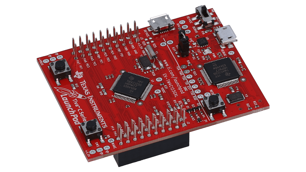
In our case, we’ll be using a basic microcontroller board TM4C123GXL, which has the same properties as an STM Nucleo Board. TI Boards for this series are termed as ‘Launchpad’ due to their ability to support other booster drivers and boards that’ll give extra support to provide more features.

Hardware Section

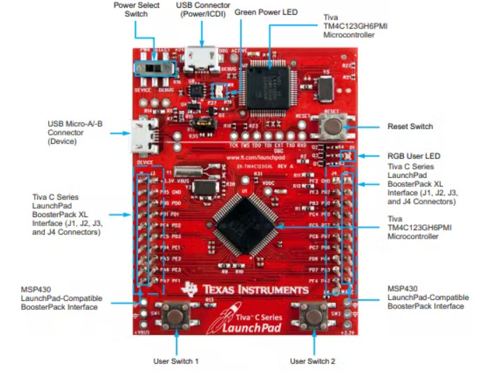
This Tivaware Launchpad (TM4C123GXL) has the following features :

Tiva TM4C123GH6PMI microcontrollerMotion control PWMUSB micro-A and micro-B connectors for USB device, host, and on-the-go (OTG) connectivity RGB user LEDTwo user switches (application/wake)Available I/O brought out to headers on a 0.1-in (2.54-mm) gridOn-board ICDISwitch-selectable power sources: – ICDI – USB device reset switch Preloaded RGB quickstart application.

Let us check more about the TM4C123GH6PMMCU :

  • 80MHz 32-bit ARM Cortex-M4-based microcontrollers CPU
  • 256KB Flash
  • 32KB SRAM
  • 2KB EEPROM
  • Two Controller Area Network (CAN) modules (requires CAN transceivers)
  • USB 2.0 Host/Device/OTG + PHYDual
  • 12-bit 2MSPS ADCs
  • motion control PWMs
  • 8 UART
  • 6 I2C
  • 4 SPI

This board provides more features than any other Arduino Board. What’s special about it, is the 32-bit MCU taking control of the board.

Software Requirements

To be able to upload and run codes on the Tiva launchpad, we need to download the IDE and library, then make a couple of configurations. Below are the software to be downloaded –

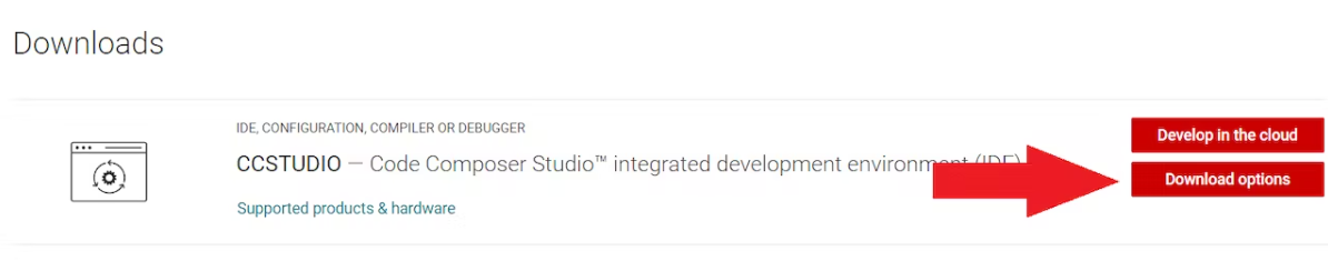
Download and Install Code Composer Studio from here. Then click on ‘Download Options‘ > select ‘Windows single file (offline)

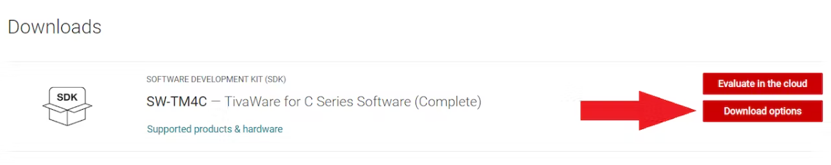
Now, Download the library for TM4Cxx family – SW-TM4C from here. Then click on ‘Download Options‘ > select ‘TivaWare for TM4C Series

Move the downloaded library file to a separate folder. It can also be kept inside the Code Composer Studio folder after its installation. Note the location of this file. There are other libraries for the particular board. Even though I used the EK-TM4C123GXL board in this article. You can use any other board, and hence download the whole library, instead of a particular board series.

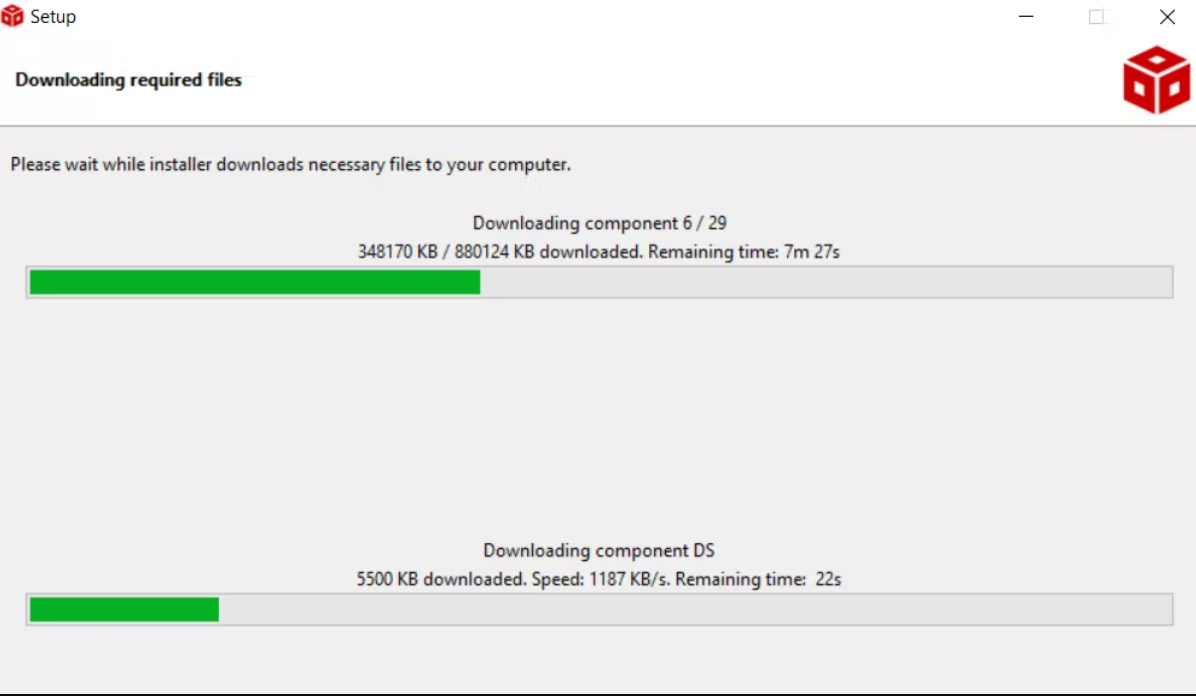
Installing Code Composer Studio

Run the CCS (Code Composer Studio) setup file. Choose the Location to install the CCS. Tip – All the code files are saved in that location. Choose ‘Custom Installation‘, since we will only be using the TM4C123GXL board, select ‘TM4C12x ARM Cortex M4F core-based MCU

Running CCS forTM4C Library –

Open CCS and create a new project > select Device – TM4C123GH6PM, connection – Stellaris ICD > Create a project with main.c fileNow, right-click on the project > and select properties > go to Build > go to the ARM Compiler section > click on the Include Options > click the icon with green plus sign to add file > browse to the downloaded library file (previously noted location)Now, let us use the ARM Linker > go to File Search Path > add the driverlib.lib file here (found at CCS installed location -..\..\TivaWare_C_Series-v.er.sion\driverlib\ccs\Debug\driverlib.lib).Once done, click ‘Apply and Close’ to continue with the build.

Alright! We can now begin with Write – Build – Upload to the Launchpad

We can also follow the Documentation for guidance on the functions used for the peripherals of the board. Download the documentation TivaWare™ Peripheral Driver Library for C Series User’s Guide(Rev. E).

PORTs – How to use them?

Ports are the peripheral pins on an embedded system, or SoC to communicate with the external environment. Whenever a port receives a HIGH or LOW signal, it communicates throughout the system.

A PORT is usually bit-packed, i.e. each port is represented with an 8-bit binary number. The number count starts from right to left. So when we mention a pin’s address as 0x0E – it means we are pointing at the pins which are O according to the below representation –X X X X O O O X
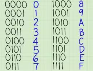
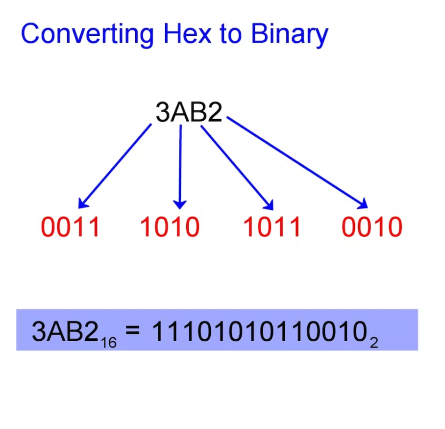
If we convert 0x0E to binary number, it becomes – 00001110. Here pins 1, 2, and 3 are pointed at to be controlled. Because the pin counting goes reverse – 7 6 5 4 3 2 1 0 (8 pins) And therefore it looks similar to the above representation. When we mention GPIO_PIN_1, we mean 0x02, in binary – 0000 0010. This turns pin 1 on port F to emit a HIGH signal. For example, if we have enabled port A, which has 8 pins. And we require the use of only 2 of the pins on that port. To enable those 2 pins according to their arrangement, we can use an 8-bit number to assign them. PortA – X X X X O X O X, which means – 0x0AWe have enabled PIN 1 and PIN 3. You can access the Github Repository of the project from here. Above we can see that O represents the pins we require to enable. We can use hexadecimal format to assign.

Therefore we shall be using the function as GPIOPinTypeGPIOOutput(GPIO_PORTA_BASE, 0x0A); Similarly, if we require to turn ON the LEDs on this port alternatively, we can use the below command:

while(1)
{
GPIOPinWrite(GPIO_PORTA_BASE,0x0A, 0x02);
SysCtlDelay(1333333);
GPIOPinWrite(GPIO_PORTA_BASE,0x0A, 0x08);
SysCtlDelay(1333333);
}

As you can see above, when the command with value 0x02 is run, only PIN 1 will be given a HIGH signal – 0000 0010 When the command with value 0x08 is run, only PIN 3 will be given a HIGH signal – 0000 1000In both commands, the other LED will turn off since it has 0 on its pin.

Congratulations! You can now understand other functions that use the ports, directly from the documentation by TI.

First Project – LED Blinking

We shall be using the inbuilt RGB LED present on the board itself. The LEDs are internally connected to GPIO 1 on Port F.

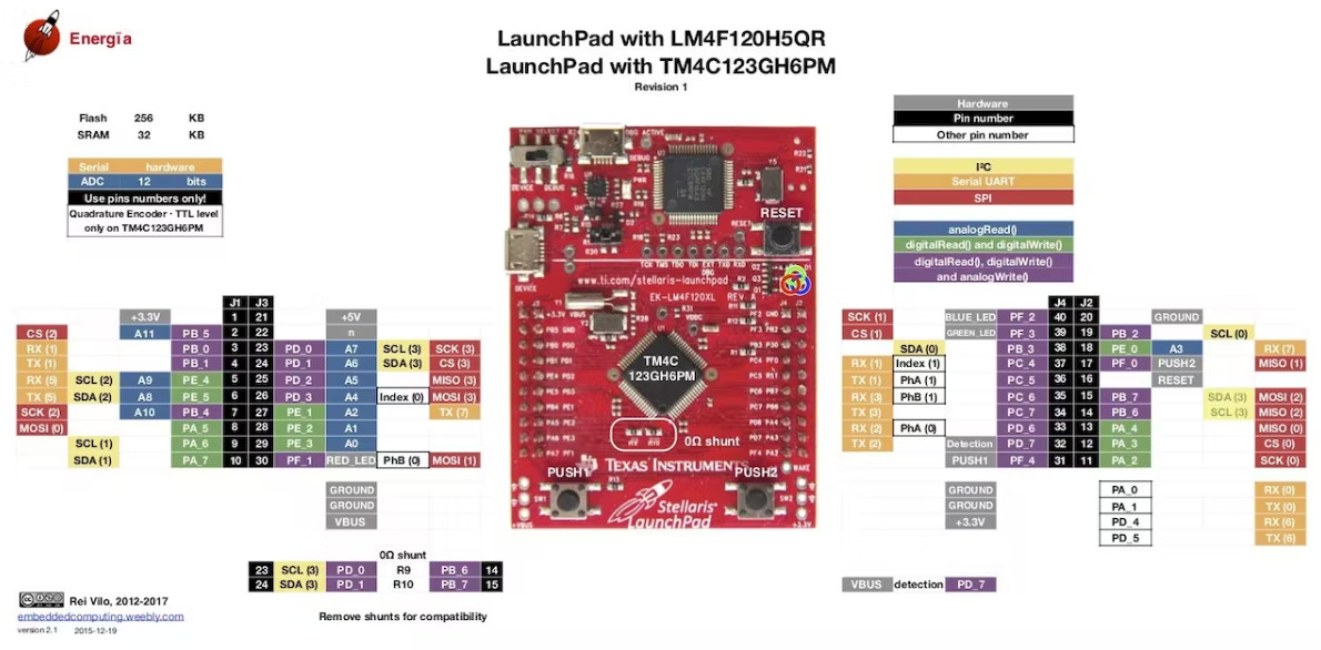
We can see from the above diagram, the pin we are trying to control has an inbuilt RED LED. If you look carefully, the pin name is PF_1. Rest PF_2 and PF_3 are Blue and Green LED respectively. You can access the Github Repository of the project from here. Also, we require to set the System Clock Frequency to 40 MHz. Therefore, we’ll use the below parameters (in sequence) — SYSCTL_XTAL_16MHZ – Precise Internal OSC- SYSCTL_USE_OSC – Forwarding the OSC- SYSCTL_USE_PLL – Generates 400 MHz, then divided by 2 = 200 MHz- SYSCTL_SYSDIV_5 – OSC divided by 5 = 40MHzUsing the SysCtlClockSet() function, we can set the clock configuration required – Final Clock frequency = 40 MHz

Code

SysCtlClockSet(SYSCTL_SYSDIV_5 | SYSCTL_XTAL_16MHZ | SYSCTL_USE_PLL | SYSCTL_USE_OSC);

Let us enable the peripheral for the GPIO of the port to be used. We’ll be enabling port F for use.

SysCtlPeripheralEnable(SYSCTL_PERIPH_GPIOF);

Enable pin 1 to be used as OUTPUT Pin:

GPIOPinTypeGPIOOutput(GPIO_PORTF_BASE, GPIO_PIN_1);

To turn ON the GPIO, use the command:

GPIOPinWrite(GPIO_PORTF_BASE,0x0E, GPIO_PIN_1);

Using the delay command is simple, use the below formula to calculate the delay in terms of clock cycle – SysCtlDelay(DelayTimeInSeconds*Clk/30)); In case we require a 1-sec delay, 1*40000000/30 = 1333333.33 loops. To test the function, use below code:

#include <stdint.h>
#include <stdbool.h>

#include "inc/tm4c123gh6pm.h"
#include "inc/hw_memmap.h"
#include "inc/hw_types.h"

#include "driverlib/sysctl.h"
#include "driverlib/gpio.h"
/**
* main.c
*/
int main(void)
{
SysCtlClockSet(SYSCTL_SYSDIV_5 | SYSCTL_XTAL_16MHZ | SYSCTL_USE_PLL | SYSCTL_USE_OSC);
SysCtlPeripheralEnable(SYSCTL_PERIPH_GPIOF);
GPIOPinTypeGPIOOutput(GPIO_PORTF_BASE, GPIO_PIN_1);
while(1)
{
GPIOPinWrite(GPIO_PORTF_BASE,0x0E, GPIO_PIN_1);
SysCtlDelay(1333333);
GPIOPinWrite(GPIO_PORTF_BASE,0x0E, !(GPIO_PIN_1));
SysCtlDelay(1333333);
}
}

We have learned another Microcontroller Board – TivaC Launchpad (32-bit Microcontroller).

AMD Ryzen Embedded R2000 Powered Mini-ITX Motherboard

IBASE Technology Inc., a world leader in the manufacture of embedded boards and solutions, rolls out the 5G-enabled MI993 Mini-ITX motherboard based on the powerful AMD Ryzen™ Embedded R2000 series processor that is capable of delivering 8 cores and 16 threads, allowing users to experience faster rendering times and overall system performance. With a host of robust features including an independent display with two HDMI ports and two DisplayPort, it is an ideal choice for digital signage, interactive kiosks, and other applications that require multiple displays.

MI993 FEATURES:

  • AMD Ryzen™ Embedded R2000 series APU on board
  • 2x DDR4 SO-DIMM sockets, Max. 32GB
  • Dual Intel® 2.5G LAN
  • 2x HDMI + 2x DisplayPort
  • 5x USB 3.1, 2x USB 2.0, 4x COM, 1x SATA III
  • 1x PCI-E (x8), 3x M.2 (B-key, E-key and M-Key)
  • Watchdog timer, Digital I/O, TPM (2.0)

The MI993 boasts two DDR4 sockets with a capacity of 32GB of memory, ensuring smooth multitasking without slowdowns. It is equipped with dual Intel 2.5G LAN for high-speed and reliable connectivity, five USB 3.1 and two USB 2.0 ports to connect to a wide range of peripherals, as well as interface options with four serial ports, one SATA port, and three M.2 sockets to support legacy devices and add expansion options as needed.

“The high-performance MI993 motherboards with AMD Ryzen R2000 processors deliver unparalleled performance and speed for powerful embedded solutions,” said Archer Chien, Director of Solution Product Planning Dept. at IBASE. “Its TPM 2.0 feature also enables hardware-based security against threats such as malware and firmware attacks.”

The MI993 is now available with AMD Ryzen R2544, R2514, R2314, or R2312 APU on board. For more information, please email sales@ibase.com.tw or visit our website at www.ibase.com.tw.

TOP PCB Companies