Advanced Multi-Camera Solutions for the Qualcomm Robotics RB5 Kit

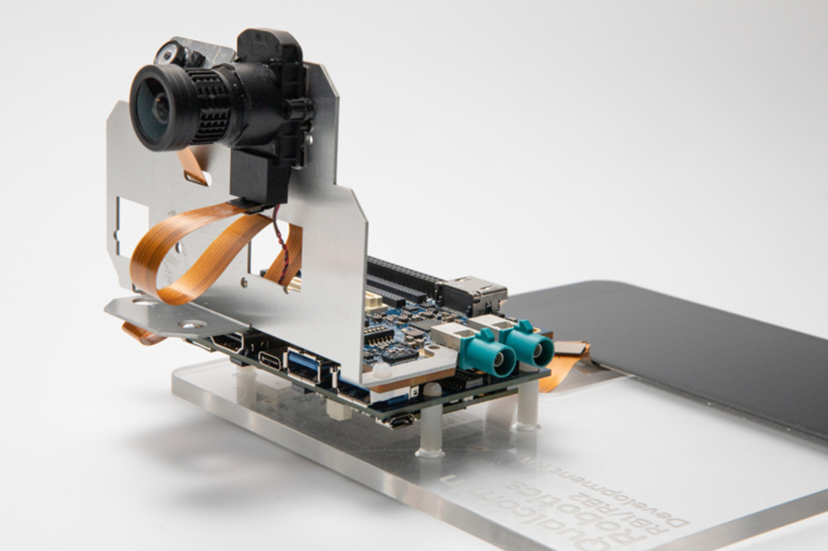
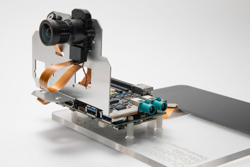
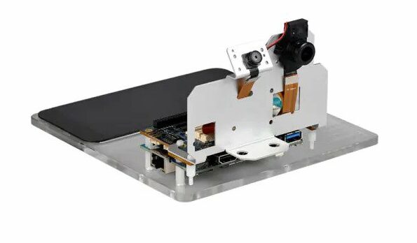
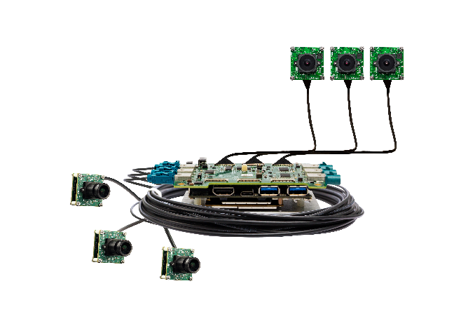
e-con Systems™, with over two decades of experience in designing, developing, and manufacturing OEM cameras, recently launched an extensive multi-camera solution to fully unlock the RB5 Kit’s potential. This solution allows connecting up to 6 cameras (MIPI or GMSL2 or a combination of both) simultaneously. e-con Systems’ cutting-edge camera solution, along with Qualcomm’s high compute power of 15 TOPS, low power consumption, and thermal dissipation, is the perfect choice for applications such as drones, delivery robots, and autonomous shopping systems.

“Qualcomm® QRB5165 processor with impressive 15 TOPS of compute power and low power consumption has opened new horizons for robotics applications. These applications demand advanced camera solutions to leverage the full potential of this RB5 Robotics kit. Recognizing this need, e-con Systems has taken the initiative to develop an innovative solution that bridges the gap and empowers the RB5 kit with robust multi-camera capabilities. Leveraging the partnership with Qualcomm, we’re confident in providing camera solutions with wide compatibility and flexibility to match our customers’ diverse needs.”, said Gomathi Sankar, Business Unit Head- Industrial at e-con Systems™.

Highlights

  • Multi-camera Support – Connect up to 6 cameras, either MIPI or GMSL2 or a combination of both, to enable imaging from multiple angles/perspectives.
  • Camera Portfolio Compatibility – Ensure compatibility with different resolutions, shutter types, chroma, HDR and NIR.
  • Full Product Development – Get a complete solution in the form of full product development, thereby simplifying the lifecycle.

Qualcomm ISP Tuning – Use e-con Systems’ solid ISP expertise for fine-tuning the Qualcomm ISP for AE, AWB, HDR, color reproduction, etc.

Video

If you are interested in evaluating this multi-camera solution, please visit the online web store and purchase the product.

Customization and integration support

e-con Systems, with deep expertise in and knowledge of various camera interfaces, provides the necessary customization services and end-to-end integration support for this solution. Unique application requirements can easily be met. So, if you are looking for any customization or integration support, please write to camerasolutions@e-consystems.com

more information: https://www.e-consystems.com/cameras-for-qualcomm-robotics-rb5-kit.asp

Banana Pi Centi S3 development board has ESP32-S3 SoC for extended wireless connectivity

Banana Pi Centi S3 development board

Banana Pi, a well-known name in the single-board computer market, has launched its latest offering, the Banana Pi Centi S3 development board. This compact embedded board has a range of capabilities, thanks to its integration with the Espressif Systems’ ESP32-S3 system-on-chip, which makes it ideal for developing projects around color display, interactive control, wireless communication, and sensor data acquisition.

As mentioned earlier, the Banana Pi Centi S3 has a powerful ESP32-S3 processor, which combines a dual-core Xtensa LX7 CPU with Wi-Fi and Bluetooth connectivity. This processor provides necessary AI acceleration through its support for vector instructions in the MCU, giving developers the ability to take advantage of these capabilities through ESP-DSP and ESP-NN libraries.

Banana Pi Centi S3 Development Board Front View

The Banana Pi Centi S3 development board comes with a 1.9-inch TFT LCD display with a resolution of 170 x 320 pixels and a rotary encoder, enabling users to interact with their projects in an intuitive and user-friendly manner. The display allows for easy visual feedback, while the rotary encoder provides a convenient means of navigation and input control.

Specifications of the Banana Pi Centi S3:

  • Processor: ESP32-S3 SoC with dual-core Xtensa LX7
  • Memory: 2 MB PSRAM
  • Storage: 8 MB flash storage
  • Wireless connectivity: Wi-Fi: 802.11 b/g/n (2.4 GHz) and Bluetooth v5.0
  • Display: 1.9-inch TFT LCD with 170×320 resolution and 8-bit 8080 parallel port
  • Encoder: Rotary encoder for input control
  • GPIOs: 9x GPIOs have been exported to the JST SH socket
  • Peripherals: I2C, SPI, PWM, UART, RMT, I2S
  • USB: USB Type-C for power and data transfer
  • Power: 5V via USB Type-C

The Banana Pi Centi S3 development board supports both USB and external 3.7V lithium battery power supply, providing users with flexibility and convenience for their projects. It features an automatic switching power supply function when dual power sources are available. This means that when both USB and a 3.7V lithium battery are connected to the board, it can seamlessly switch between the power sources based on their availability and priority.

The Banana Pi Centi S3 development board offers extensive software support as it is compatible with popular programming languages and development environments such as MicroPython. The manufacturer has provided documentation and sample code with some demo videos available through its official Wiki page.

Orange Pi 5 Plus SBC is equipped with Rockchip RK3588 SoC

Orange Pi 5 Plus SBC

The Orange Pi 5 Plus SBC has recently made its debut, offering a powerful computing solution for enthusiasts and professionals alike. Inside the Orange Pi 5 Plus SBC is the popular Rockchip RK3588 processor, which provides high performance and power efficiency.

The RK3588 is a highly capable processor featuring an octa-core Arm Cortex-A76/A55 CPU and an Arm Mali-G52 GPU, enabling the board to handle demanding heavy workloads. With this processing power, users can extend their use case into a wide range of applications, from media streaming and gaming to AI and machine learning projects.

Specifications of the Orange Pi 5 Plus SBC:

  • Processor: Rockchip RK3588 with an octa-core Arm Cortex-A76/A55 CPU and Arm Mali-G52 GPU
  • Memory: Up to16 GB LPDDR4 RAM
  • Storage: Up to 256 GB eMMC module can be attached, MicroSD card slot for up to 128 GB, QSPI Nor Flash up to 32 MB, and M.2 2280 slot for NVMe SSDs (PCIe 3.0 x4) up to 2,000 MB/s
  • Video: 2x HDMI 2.1 output with up to 8K resolution support at 60 fps, 1x MIPI DSI TX 4 Lane with up to 4K at 60 Hz.
  • Camera: MIPI-CSI interface for connecting cameras
  • Audio: 3.5mm audio jack, onboard microphone
  • Connectivity: Gigabit Ethernet and M.2 slot supporting 2230 Wi-Fi 6, Bluetooth module
  • Power: Supports USB Type-C power supply and 5V at 4A.
  • Software: OrangePi OS (Droid), OrangePi (Arch), Ubuntu 22.04, Debian 11, and Android 12

The Orange Pi 5 Plus SBC offers multiple operating system options, including Android and various Linux distributions such as Ubuntu and Debian. This allows users to choose the OS that best suits their needs and preferences according to the application.

The board provides several connectivity options, ensuring seamless integration into various projects. With its PCIe and M.2 slots, users have the flexibility to expand the capabilities of the SBC by adding additional peripherals such as SSDs or other expansion cards.

The Orange Pi 5 Plus SBC can be purchased on Amazon for $138.99 USD for the 16 GB RAM variant.

Qualcomm Robotics RB1 and RB2 development kits for next-generation robotics and IoT applications

Qualcomm Robotics RB1 and RB2 platform

Qualcomm Technologies has recently launched the Qualcomm Robotics RB1 and RB2 development kits, designed to accelerate the development and deployment of advanced robotic systems and IoT applications, enabling developers to create advanced solutions with ease. The devices are optimized with smaller form factors and lower power consumption, making them effective for the targeted industry.

The new Qualcomm QRB2210 processor powers the Qualcomm Robotics RB1, and the RB2 development kit has Qualcomm QRB 4210 processor. These high-performance processors offer excellent computing performance and power efficiency. The advanced Adreno GPU ensures superior graphics rendering capabilities, enabling developers to create visually immersive robotic applications.

The Qualcomm Robotics RB1 development kit is equipped with a customized 64-bit Arm Cortex-A53 quad-core processor clocked up to a frequency of 2.0 GHz and is integrated with Qualcomm Adreno GPU 702 at 845 MHz. It supports IEEE 802.11a/b/g/n/ac Wi-Fi connectivity along with Bluetooth 5.0.

One of the standout features of the Qualcomm Robotics RB1 platform is its ability to support machine vision. With the capability to accommodate up to two cameras, this platform enables the onboard intelligence to seamlessly merge visual data with other high-precision sensors from TDK. This integration empowers robotic systems to harness the power of machine vision, enabling applications such as autonomous navigation.

Qualcomm Robotics RB1 and RB2 development kits

The Qualcomm Robotics RB2 platform takes AI processing to the next level by incorporating a dedicated Digital Signal Processor (DSP). This DSP enables on-device AI processing, providing a high-performance solution for executing AI algorithms efficiently. With support for all major AI frameworks and networks, developers can leverage the power of AI to enhance the capabilities of their robotic systems.

“Qualcomm Technologies is committed to fueling innovation, creating new business opportunities, enabling the next generation of 5G connectivity and premium edge- AI — and that starts with ensuring accessibility and performance across the ecosystem,” said Dev Singh, Vice President, Business Development and Head of Building, Enterprise & Industrial Automation, Qualcomm Technologies, Inc.

The platform incorporates advanced features such as multi-frame noise reduction (MFNR) for capturing snapshots with reduced noise, temporal noise reduction for capturing high-quality videos, and electronic image stabilization (EIS) for smooth and stable footage.

In addition to the powerful hardware, the Qualcomm Robotics RB1 and RB2 Development Kits offer a range of other notable features. These kits provide developers access to a comprehensive set of tools, libraries, and software frameworks to facilitate rapid prototyping and development.

Adafruit Feather RP2040: Another feather board but with a Raspberry Pi microcontroller

Adafruit Feather RP2040

The Adafruit Feather RP2040 is an embedded device with the popular Feather form factor, designed to cater to the needs of long-range IoT wireless communication. At the heart of the Adafruit Feather RP2040 is the Raspberry Pi RP2040 microcontroller, which ensures high performance and low power.

The famous Raspberry Pi RP2040 microcontroller boasts a dual-core Arm Cortex-M0+ processor, running at 133 MHz, providing sufficient processing power for various applications. With 264 kB of SRAM and 8 MB of SPI flash memory, the RP2040 allows for efficient data storage and quick retrieval, ensuring smooth operation.

Specifications of the Adafruit Feather RP2040:

  • Processor: Raspberry Pi RP2040, featuring dual-core Arm Cortex-M0+
  • Storage: 8 MB of SPI flash memory for program and data storage
  • Memory: 264kB RAM
  • Connectivity: RFM95 LoRa radio for long-range wireless communication
  • GPIOs: 21x GPIO pins with four 12-bit ADCs, two I2C, two SPI and two UART peripherals, 16x PWM outputs, and eight digital non-ADC/non-peripheral GPIO
  • Power: 3.3V operating voltage and a built-in USB Type-C port, along with a 2-pin LiPo battery connector
  • Connector: STEMMA QT connector for easy interfacing or I2C devices
  • Button: Reset and bootloader select button
  • Software: Easy bootloader installation for easy programming
  • Dimensions: 50.8mm x 22.8mm x 7mm

In addition to these specifications, the Adafruit Feather RP2040 offers an array of other features, including a wide range of GPIO pins, allowing users to connect various sensors, actuators, and peripherals. The onboard LoRa radio enables long-range communication, making it suitable for applications requiring remote data transmission over extended distances.

Video

When it comes to software support, the Adafruit Feather RP2040 is backed by Adafruit’s extensive library of Arduino libraries and CircuitPython support. This makes it easy for developers to get started and leverage the vast ecosystem of existing libraries and examples. The RP2040 microcontroller inside the Adafruit Feather RP2040 comes with a built-in USB UF2 bootloader, which is stored in a permanent ROM (Read-Only Memory). This bootloader plays a crucial role when you want to program new firmware onto the board.

Adafruit Feather RP2040 is currently available for purchase at $11.95 USD on its official product page.

Adafruit Metro M7– An Arduino Uno layout board with wireless connectivity

Adafruit Metro M7 board

Adafruit has recently unveiled its Adafruit Metro M7 board, which has an Arduino Uno layout and combines the added convenience of built-in wireless connectivity. With its features and robust hardware, the Metro M7 with AirLift offers a comprehensive platform for a wide range of projects, making it an ideal addition to Adafruit’s extensive lineup of development tools.

At the heart of the Adafruit Metro M7 lies the powerful NXP iMX RT1011 processor. This ARM Cortex-M7-based microcontroller boasts a clock speed of 500 MHz, enabling it to handle complex tasks with ease. The iMX RT1011 processor provides enough processing power for resource-intensive applications, making it a good choice for projects requiring real-time responsiveness and high-speed data processing.

Apart from its powerful processor, the Adafruit Metro M7 board offers a range of other features that enhance its functionality and flexibility. One of its key highlights is the built-in AirLift module, which provides Wi-Fi connectivity. This module is based on the popular ESP32 co-processor, allowing seamless integration with wireless networks and enabling communication with other devices.

Adafruit Metro M7 board vs Coin

Specifications of Adafruit Metro M7 board:

  1. Processor: NXP iMX RT1011 processor featuring Arm Cortex M7 
  2. Co-processor: AirLift WiFi Co-processor with ESP32-WROOM-32 module
  3. Memory: 28KB SRAM
  4. Storage: 8MB of QSPI XIP flash
  5. Power: 6-12VDC barrel jack or USB type-C
  6. Connector: SWD connector for debugging and STEMMA QT connector for interfacing external I2C devices
  7. Dimensions: 53.2mm x 72mm
  8. Weight: 22.5 grams

In terms of software support, the Metro M7 board is compatible with the popular CircuitPython development programming language, making it accessible and user-friendly for both beginners and experienced developers. The same layout as the Arduino Uno means that the user can partially use Arduino Uno accessories for quick and easy integration of various sensors, actuators, and other peripherals into projects, simplifying the prototyping process.

Adafruit has provided detailed documentation on installing the UF2 bootloader on the RT10xx microcontroller to assist users in getting started with the board and leveraging its capabilities.

Adafruit Metro M7 board is currently available for purchase at $29.95 USD on its official product page.

MI997 Mini-ITX Motherboard for 12th Gen Intel Core Processor

IBASE Technology Inc., a leading provider of embedded board and solutions, launches the MI997 Mini-ITX motherboard designed for 12th Gen Intel® Core™ processors (codenamed Alder Lake PS) that supports faster DDR5 memory and takes advantage of a hybrid architecture that combines performance and efficient cores, outperforming previous generations in single-core and multi-core workloads.

The MI997 has two DDR5 SO-DIMM sockets with 64GB capacity, providing higher bandwidth and improved power consumption. M.2 slots (B-key, E-key, 2x M-Key) enable the installation of high-performance storage devices for faster boot and load times, and robust wireless (WiFi, Bluetooth) connections. The MI997 comes with HDMI (2.0a), LVDS, and 2x DisplayPort (1.4a) graphics interfaces, dual Intel 2.5G Ethernet controllers, and an abundance of I/O peripheral connectivity with four USB 3.2, two USB 3.1, and two USB 2.0 ports.

MI997 FEATURES:

  • 12th Gen Intel® Core™ i7/i5/i3 and Celeron® processors (formerly Alder Lake PS)
  • 2x DDR5 SO-DIMM sockets, Max. 64GB
  • Intel® processor integrated graphics supports HDMI (2.0a), LVDS and 2x DisplayPort (1.4a) (DP++)
  • Dual Intel® 2.5G LAN
  • 4x USB 3.2, 2x USB 3.1, 2x USB 2.0, 4x COM, 2x SATA III
  • 1x PCI-E (x1) [Gen.3.0]; 4x M.2 (B-key, E-key and 2x M-Key)
  • Watchdog timer, Digital I/O, iAMT(16.0), fTPM
  • 12V~24V DC input

In addition to its stable performance and advanced connectivity capabilities, the MI997 also features Intel Active Management Technology (iAMT 16.0) for easy remote management, built-in RAID support, fTPM, and 12V to 24V suitable for various industrial environments. Overall, the IBASE MI997 Mini-ITX motherboard is a powerful and reliable IoT edge solution for digital signage, POS/kiosk, and automation control applications.

For more information, please visit www.ibase.com.tw

Join the Open Source Hardware Movement and Fabricate Your Own Wio Terminal for A Chance To Get 2x Free PCBA from Seeed Fusion

Hey Community! Are you ready to unleash your creativity and take the open-source hardware movement to the next level?

We are passionate about open-source hardware and believe that it has the power to transform the world. That’s why we’re taking it to the next level with open manufacturing, making it possible for anyone to reproduce and manufacture the Seeed Studio Wio-Terminal. With the potential to unlock limitless creativity and innovation, the Wio Terminal is more than just a microcontroller – it’s a game-changer!

We are committed to the open-source hardware movement, and in that spirit, we have taken this step further into open manufacturing. We believe that opening the manufacturing process will unlock immense potential for innovation and creativity.

Seeed Studio Wio Terminal is an open-source hardware initiative that we have developed and maintained with passion.

A widely-acknowledged IoT development platform that supports Arduino and MicroPython and equipped with Bluetooth and Wi-Fi, the Wio Terminal has already made its mark in smart homes, industrial automation, education and research.

We are now offering all the production files and documentation required to modify and  manufacture the Wio Terminal, enabling anyone to replicate, produce, and even commercialize their own versions of this amazing device. We believe that open manufacturing will facilitate innovation and encourage more people to participate in hardware design and improvement, collectively promoting the development of hardware technology. We can’t wait to see the amazing things that you will create with the Wio Terminal, and we encourage you to share your designs and ideas on our platform.

Exploring more about Wio-Terminal: Fabricatable Open Source Hardware on Seeed Studio’s Github


These design files are freely available for anyone to access, use and modify. For convenience, we also include these design files in the Wio Terminal wiki .

We are looking for partners who share our philosophy to promote the development of open-source hardware and open manufacturing together. Whether you are a corporation, educational institution, research institution, or individual developer, as long as you have passion and innovation, we welcome you to join us. Let’s build an open, innovative, and fair hardware ecosystem together.

Fusion Quick Pass

In order to give back to our community and make your great ideas a reality, Seeed Studio Fusion is launching the Wio Terminal open source movement to help capable engineers, individual developers turn their designs into real products.

For those who wish to design and manufacture their own versions of Wio Terminal, our SeeedStudio Fusion Agile manufacturing offers quick and high-quality PCB Assembly service. One more thing to clarify is that please make sure that you are capable of designing and have all the production files ready for us. Moreover, once your idea/proposal is approved by us, each person is limited to two PCBA boards 100% completely FREE for one Wio Terminal design, including PCB fabrication, the cost of parts, assembly and free worldwide delivery.

Getting excited? Keep reading to find out more.

How to join the open source hardware movement and fabricate your own wio terminal and get a $30 Cash Prize?


How to join the open source hardware movement and fabricate your own wio terminal?

  • Please fill out the form: https://forms.gle/uic7bVA8SnuJLFR3A to submit your Wio Terminal design proposal.
  • One more thing to clarify is that please make sure that you are capable of designing and have all the production files ready for us. If we approve your design proposal, we will contact you via email & Linkedin as soon as possible, then you can start to prepare your Gerber & BOM file. (Pls note that when preparing your BOM file, please preferentially select materials in Seeed Fusion OPL, which will speed up the production of your order.)
  • All of design files are freely available for anyone to access, use and modify. You can explore more about Wio-Terminal: Fabricatable Open Source Hardware on Seeed Studio’s Github.
  • If you have any questions, please do not hesitate to contact our Seeed Fusion customer support team at fusion@seeed.io for further consultation.

What kind of secondary development and design can you do based on the Wio Terminal?

Here are some initial ideas we’ve provided to help you get started.

1. Modification of Wio Terminal Boards

You can modify the interfaces according to your needs and make suitable changes to the casing. Don’t hesitate to fill out the form and share your design thoughts with us to receive a sponsorship of 2PCS free PCB Assembly. If you share your final project with us and receive over 20 likes on Seeed Studio’s Twitter or LinkedIn, we are willing to offer you a cash prize of $30USD.

2. Wio Terminal Peripheral Accessories Design

Peter, a developer from the community, has designed a QWERTY keyboard for Seeed Studio’s Wio Terminal that operates without an IC. The keyboard matrix is scanned through GPIO and the software is programmed using CircuitPython. We encourage you to submit your innovative ideas for accessory design based on Wio Terminal by filling out the form and sharing them with us.

Scale up your Wio-Terminal Creation with Seeed Studio Co-Create Program!

We will invite well received wio-terminal designs to the Seeed Studio Co-Create Program, where your products can be listed, sold and shipped directly by Seeed on the Seeed Studio Bazaar. We will also support designers to reach thousands of like-minded customers and distributors with Seeed’s global sales channels and social media presence.

Join the Open Manufacturing Movement Together!

Manufacturing and Assembling your Wio Terminal design with the help of Seeed Fusion PCBA Agile Manufacturing Service. Then, publish your Wio Terminal designs on your own platform and we would love to share them on Seeed Studio social media.

 * By participating in this event, you agree to review your experience with us and allow us to share the design with the community on our social media platforms (Facebook, Twitter, Linkedin, discord, blog, etc.). The design does not need to be open-sourced and production files will not be shared with the public (unless you want to).

We’re excited to take this journey with you. Let’s create, innovate, and shape the future of open manufacturing together!

Installation of Casa OS on Raspberry Pi

In this tutorial, I will show you how to build a beautiful home server with Raspberry Pi and CasaOS.

Things Needed

All you need is a Raspberry Pi 4B board, That’s all.

Introduction to Casa OS

CasaOS is a simple, easy-to-use, elegant open-source home cloud system that allows you to run self-hosted apps on your Raspberry Pi or other Linux devices. You can manage your files, share them across the network, protect your private data, and freely add disks and expansion spaces. CasaOS also has an app store with over 20 pre-installed Docker-based apps and 50+ community-verified apps.

If you want to try out the casa os before the installation, use this demo site.

The username is casaos, and the password is also the same.

CasaOS fully supports Raspberry Pi. Also, additional computers and development boards are fully compatible including Ubuntu, Debian, Raspberry Pi OS, and CentOS with one-liner installation.

Get PCBs for Your Projects Manufactured (Sponsor)

It’s recommended to check out PCBWAY for ordering PCBs online for cheap!

You get 10 good-quality PCBs manufactured and shipped to your doorstep for cheap. You will also get a discount on shipping on your first order. Upload your Gerber files onto PCBWAY to get them manufactured with good quality and quick turnaround time. PCBWay now could provide a complete product solution, from design to enclosure production. Check out their online Gerber viewer function. With reward points, you can get free stuff from their gift shop.

Hardware Compatibility

  • amd64 / x86-64arm64armv7

System Compatibility:

  • Debian 11 (✅ Tested, Recommended)
  • Ubuntu Server 20.04 (✅ Tested)
  • Raspberry Pi OS (✅ Tested)

Quick Setup of CasaOS

Now we have enough information about the Casa, let’s try to install it. Before installing the casa, first boot your Raspberry Pi with Raspian OS. Use the Raspberry Pi imager tool to do that.

Once installed, the software opens the tool.

Next, choose the OS type.

Then select the drive. One of the great features of this tool is we can add the SSH and Wi-Fi credentials directly into the OS file, even without turning on the Raspberry Pi. For that, select the settings icon in the tool.

Next, start burning the OS into the SD card.

Once the writing is finished, insert the SD card into the Raspberry Pi.

Then power on the device. The first time it will take some time to boot and connect to Wi-Fi. In about 5–10 minutes look at your router status, and you can see there will be a new device connected to your router.

Next, use serial terminal software to communicate with SSH.

Then run this command to install the CasaOS.

curl -fsSL https://get.casaos.io | sudo bash

You will see this message on the terminal, and the entered command will try to install all the necessary components regarding the CasaOS.

Once the installation is finished, you will see this kind of message also the IP address of the Casa Server.

Next type the IP in your Brower, and you will see the CasaOS on screen.

And then click Go and enter your access details for the CasaOS.

Finally, you will see the beautiful home screen.

Next, click on the app store, and you can see there is a bunch of available apps.


Also, open the file manager, and you will see all the files of your Raspberry Pi,

Not only the system drive, but It will show you the removable drive also.

Wrap-Up

That’s all about the CasaOS, it’s a very beautiful, simple, and lightweight OS, right? And it also includes a bunch of apps, including Pihole, Plex, and many more.

Will see you in another tutorial.

Brushed DC Motor Speed Controller Using Radio Control (RC) Remote

This is a Brushed DC motor controller designed to control one brushed DC motor up to 5A. It can control the speed of the DC motor using a Radio Control (RC) System. This Arduino compatible hardware converts RC PWM signal into 0 to 100% duty cycle PWM which further drives high current load using MOSFET. The project consists of an Atmega328 microcontroller, and a gate driver optocoupler provides isolation between MOSFET and microcontroller circuit to prevent high voltage and noise traveling from the motor and related circuit to the microcontroller. The circuit can drive a motor up to 5A with a power supply of 12V to 40V DC. The board has the option to mount higher voltage and current MOSFET, which can drive higher Voltage and current load. In this case don’t install Q2, install Q1 MOSFET FDH3632, and replace diode D2 with a higher current diode.

Note: This board will work with any standard RC remote. In this project, we tested it with HOTRC DS-600 6CH 2.4GHz Radio System. Standard RC radio outputs is 50Hz – 1mS(1000uS) to 2mS(2000uS)

Arduino Programming

Arduino code is available as a download below and the user will able to test the board using this code. Feel free to modify the code as per requirement.

More info for programming a new Atmega328 chip: https://docs.arduino.cc/built-in-examples/arduino-isp/ArduinoToBreadboard

Power Supply

  • For Motor up to 12-15V the board can work with a single supply. Close jumper J1 and Jumper J2, and use connector CN1 to apply 12V to 15V DC.
  • For Higher Voltage up to 90V (Limited due to DC bus capacitor), the board requires dual supply, one for DC motor load, 2nd for gate driver 12V to 15V on CN3.
  • It is advisable to use 3 separate power supplies for large-size motors such as 90V, 20A. such as 1. Logic supply 5V. 2. Gate Driver Supply 12V to 15V and Load supply 90V DC.
  • Use Connector CN1 for load power supply up to 90V DC, Gate driver requires 12V to 15V power at CN3, and use CN5 Pin 1-5V DC and Pin 3 GND to power the microcontroller.

Features

  • Power Supply up to 40V (Read description for higher power input)
  • Load Current Up to 5Amps
  • Dual Supply 12V-15V DC for Gate driver and 40V for the Load
  • On Board Power LED
  • Optocoupler MOSFET Gate driver for noise immunity and provides isolation between micro-controller and MOSFET
  • Arduino Compatible Hardware to create many applications
  • On Board Connector for Arduino Programming and Boot-Loader burring
  • Barrier Terminal Blocks for easy connection of Motor and power supply
  • Onboard 5V Regulator for single supply operation for lower voltage motor
  • PCB Dimensions 74.45 x 52.23 mm
  • 4 x 3mm Mounting Holes

Connections and Other Details

  • CN1: Pin 1 = + DC Supply for Load, Pin 2 = GND
  • CN2: DC Brushed Motor, Pin 1 = Motor, Pin 2= Motor
  • CN3: Gate Driver Power Supply 12V to 15V, Pin 1 = +12V to 15V, Pin 2 = GND
  • CN4: Programming and Boot-Loader, Pin 1 = TX, Pin 2 = RX, Pin 3 = Reset, Pin 4 = GND, Pin 5 = VCC, Pin 6 = D11, Pin 7 = D12, Pin 8 = D13
  • CN6: RC Receiver, Pin 1 = D3 – RC PWM Input, Pin 2 = VCC 5V, Pin 3 = GND
  • J1: For lower voltage single supply option, Close Jumper 1, Jumper J2, Use CN1 to power 12V to 15V DC.
  • J2: For Lower Voltage motor 12V to 15V Close Jumper J2 to power the Gate driver
  • For Higher Voltage motor such 90V, advisable to use three power supply, Load Supply CN1, Gate driver Supply 12V to 15V CN3, Logic supply 5V CN5, open jumper J1 and J2 in this case
  • CN5: Do not Install
  • D3: Power LED

Schematic

Parts List

NOQNTYREF.DESC.MANUFACTURERSUPPLIERSUPPLIER'S PART N0
11CN12 PIN BARRIER CONNECTOR PITCH 9.53MMTE CONNECTIVITYDIGIKEYA98482-ND
21CN22 PIN BARRIER CONNECTOR PITCH 9.53MMTE CONNECTIVITYDIGIKEYA98482-ND
31CN32 PIN SCREW TERMINAL PITCH 5.08MMPHOENIXDIGIKEY277-1247-ND
41CN48 PIN MALE HEADER PITCH 2.54MMWURTHDIGIKEY732-5321-ND
52CN5,CN63 PIN MALE HEADER PITCH 2.54MMWURTHDIGIKEY732-5316-ND
63C1,C6,C7100nF/50V CERAMIC SMD SIZE 0805YAGEO/MURATADIGIKEY
71C210uF/16V CERAMIC SMD SIZE 0805YAGEO/MURATADIGIKEY
81C3100nF/100V THT FILMCORNELLDIGIKEY160104K160C-F-ND
91C4470uF/100V ELECTROLYTICNICHICONDIGIKEY493-1379-ND
101C5220uF/25V ELECTROLYTICRUBYCONDIGIKEY1189-2913-ND
112SHUNTSHUNT FOR JUMPER J1 AND J2SULINS CONNCTDIGIKEYS9001-ND
123D1,R6,C8DNP
132C9,C1022PF/50V CERAMIC SMD SIZE 0805YAGEO/MURATADIGIKEY
141D2MBR20200CTG TO263ONSEMIDIGIKEYMBR20200CTGOS-ND
151D3LED RED SMD SIZE 0805OSRAMDIGIKEY475-1278-1-ND
162J1,J2JUMPER 2PIN MALE HEADER PITCH 2.54MMWURTHDIGIKEY732-5315-ND
171Q1FDH3632 OPTIONAL TO247 ON SEMIDIGIKEYDO NOT INSTALL
181Q2IRFZ44 INFINEODIGIKEYIRFZ44NSTRLPBFTR-ND
191R110K 5% smd size 0805YAGEO/MURATADIGIKEY
201R2470E 5% smd size 0805YAGEO/MURATADIGIKEY
211R34.7E 5% SMD SIZE 0805YAGEO/MURATADIGIKEY
221R40E SMD SIZE 0805YAGEO/MURATADIGIKEY
231R51M 5% SMD SIZE 0805YAGEO/MURATADIGIKEY
241R71K 5% SMD SIZE 0805YAGEO/MURATADIGIKEY
251U1LM78M05 SMD DPAKTIDIGIKEYMC78M05CDTGOS-ND
261U2ATMEGA328TQPF-32MICROCHIPDIGIKEYATMEGA328PB-AURCT-ND
271U3TLP350/TLP250TOSHIBADIGIKEYTLP350F-ND
281X116MhzECS INCDIGIKEYX1103-ND

Connections

Gerber View

Photos

Video


TLP350 Datasheet

TOP PCB Companies