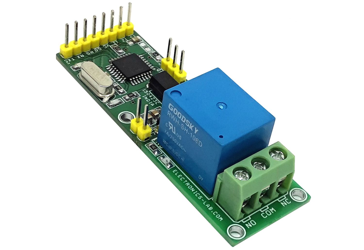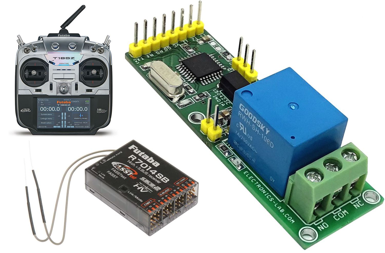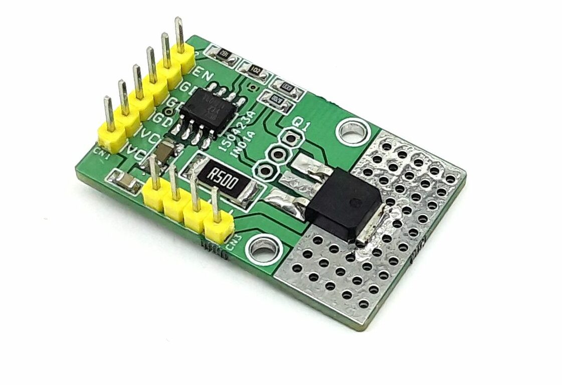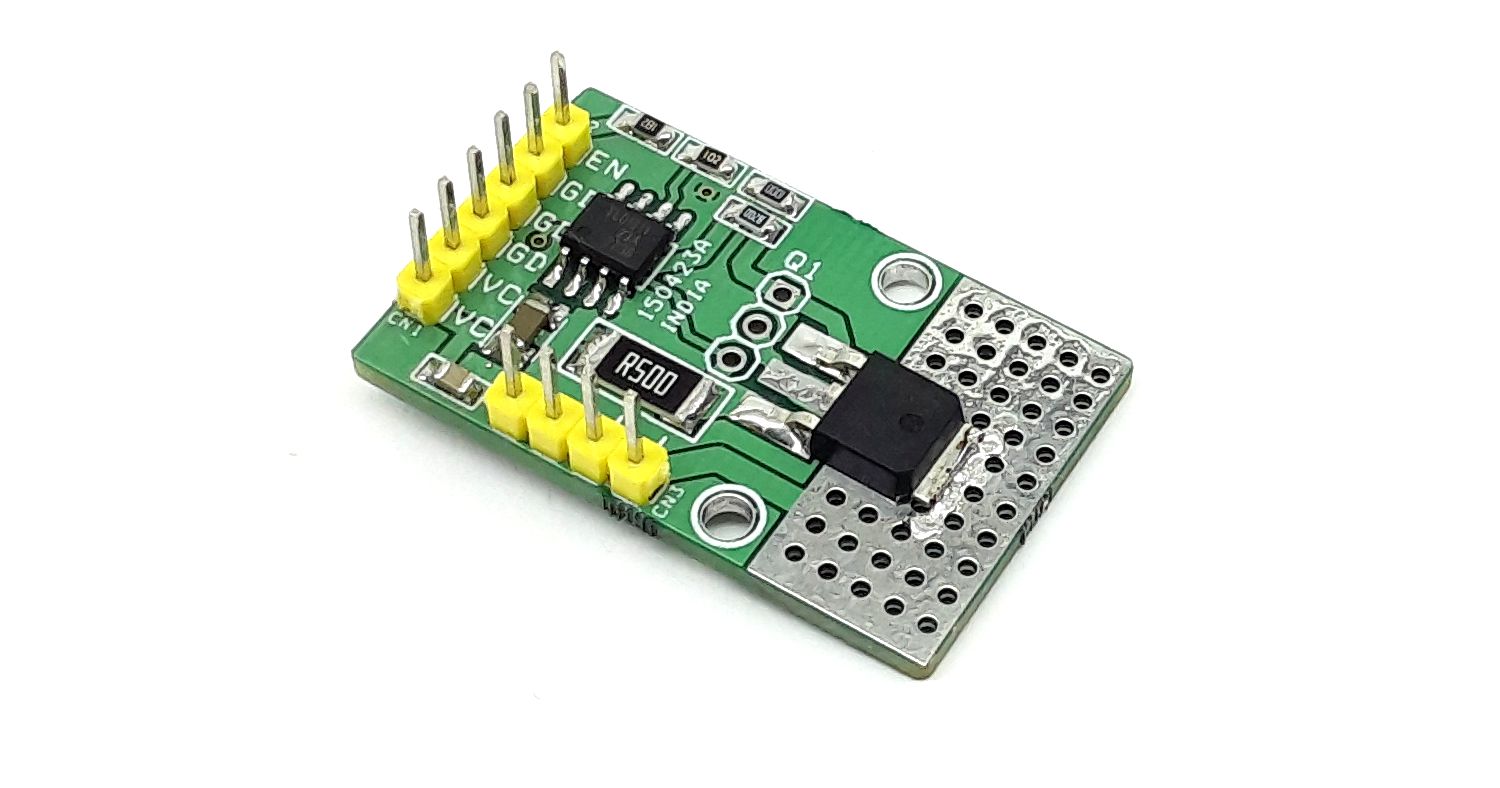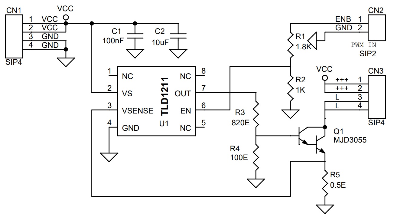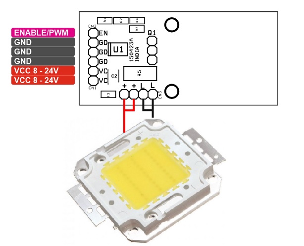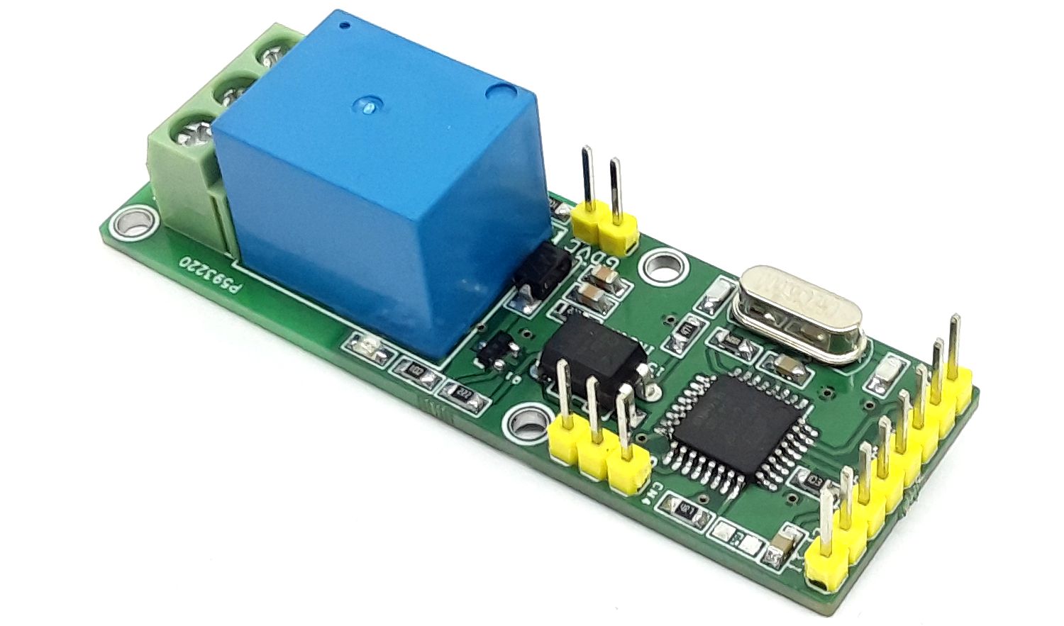
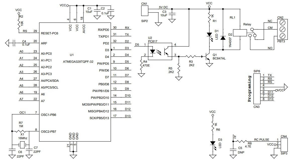
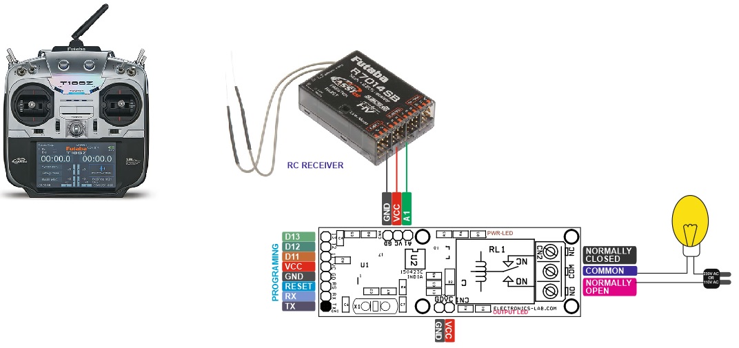
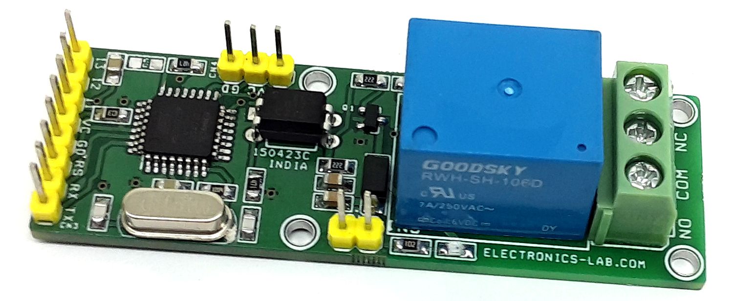
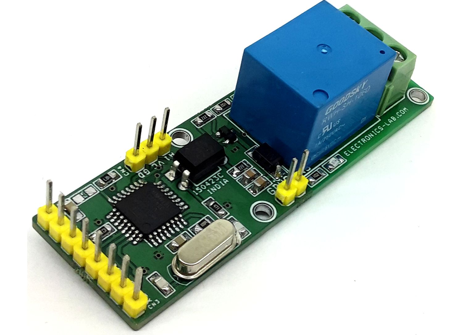
This RC Relay project enables control of large current devices using a Radio Control (RC) System. This RC switch converts hobby radio control (RC) pulses to control the on/off state of the Relay. On board LED indicates the output. The board is Arduino compatible and the example code can be modified as per user requirements. The relay ON/OFF threshold can be set as per user requirements. The Arduino sample code enables momentary ON/OFF control of the relay, but this can be modified for Latch output. The relay can handle a load up to 7A – 30V DC or 7 Amps 230AC Loads such as bulbs, LEDs, motors, fans, heaters etc. The project can be connected to an unused RC channel. It operates with 5V DC and draws 60mA current when the relay is ON. 3 Pin male header helps the user to connect the RC receiver. The project is Arduino compatible and can be programmed using Arduino IDE with the help of an onboard programming connector. The project consists of an Atmega328 microcontroller, programming/bootloader connector, relay, BC847 BJT transistor to drive the relay, freewheel diode for protection from the relay, and U2 PC817 provides isolation between the microcontroller and relay. D1 LED indicates output, D3 LED power LED. connector CN2 relay switch connection, connector CN1 5V supply input.
Arduino Programming
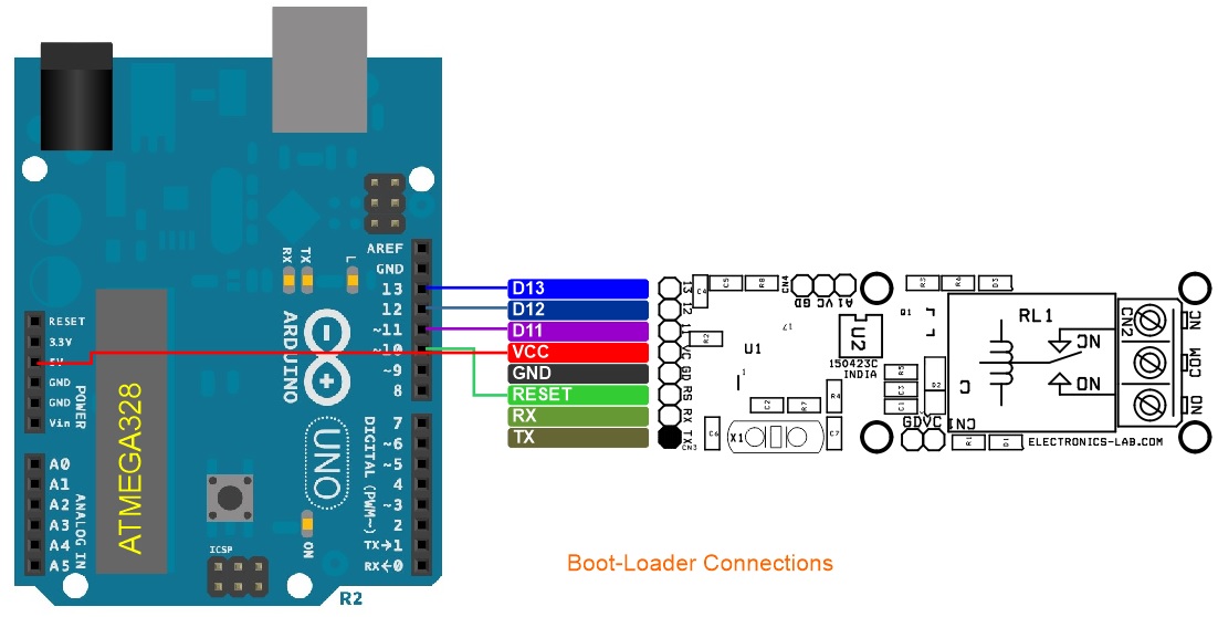
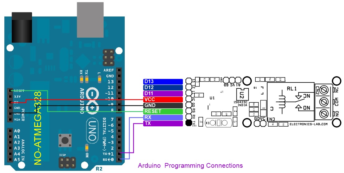
Arduino Code is available as a download below. The user will be able to operate the Relay while the RC radio joystick is pulled down and the pulse width is between 1460 – 1090uS. The user may change this value in the code. Connector CN3 is provided to burn the bootloader and upload the Arduino code. Please refer to the connection diagram for programming.
More info about new Atmega328 chip programming: https://docs.arduino.cc/built-in-examples/arduino-isp/ArduinoToBreadboard
Arduino Code Credits: “Tech Home” YouTube Channel
Features
- Supply 5V DC
- Current 60mA when Relay is On
- RC Signal 1000 to 2000 uS
- Relay Switch Activate Threshold Time 1460 – 1090uS
- Relay Output-Load 230V AC Up to 7Amps, 30V DC up to 7Amps
- On Board Power LED
- On Board Output LED
- Header Connector for RC Receiver Interface
- 4 x 2.5mm Mounting Holes
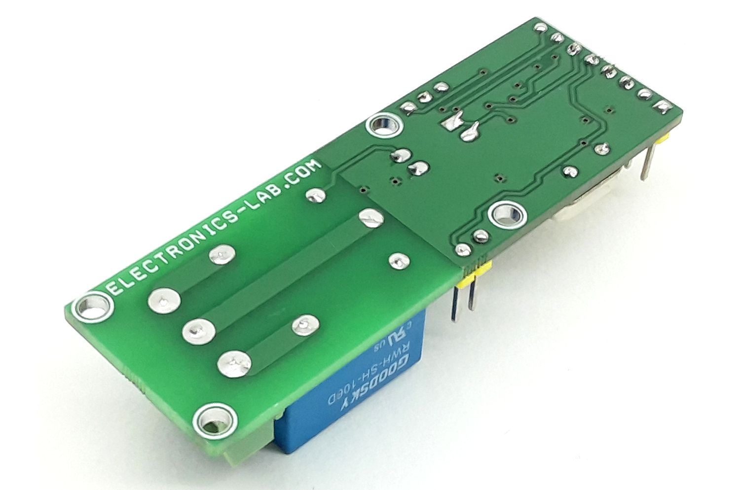
- PCB Dimensions 66.68 x 22.23mm
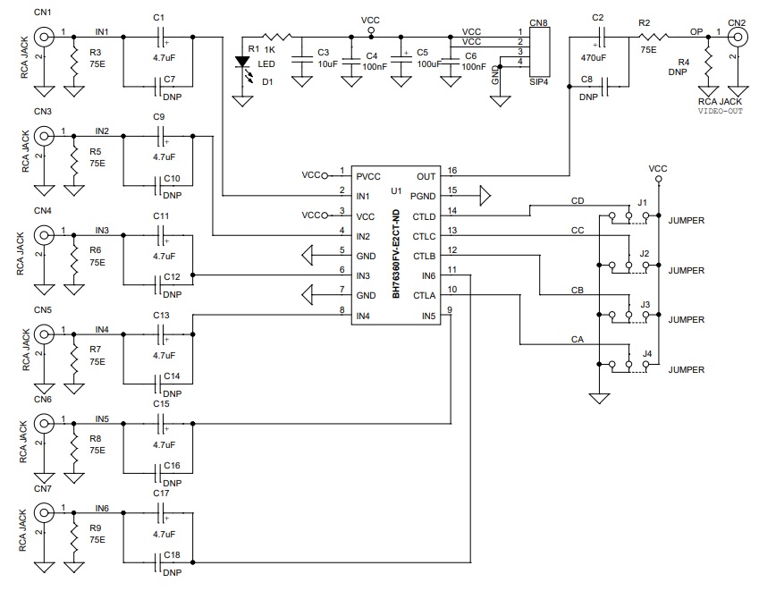
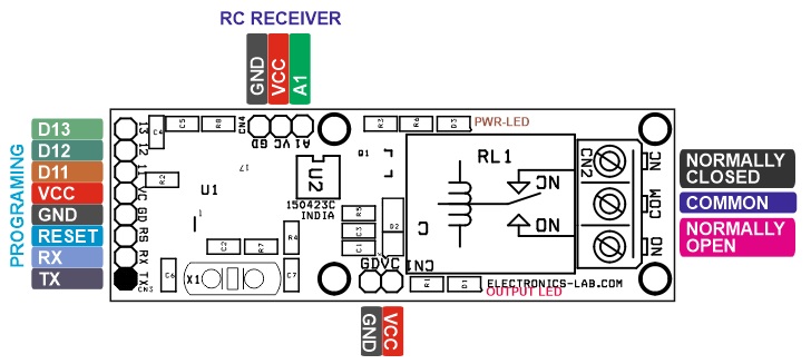
Connections and Other Details
- CN1: Pin 1 = VCC, Pin 2 = GND
- CN2: Relay Switch/Output Pin 1 = Normally Closed, Pin 2 = Common, Pin 3 = Normally Open
- CN3: Programming Connector Pin 1= TX, Pin 2 = RX, Pin 3 = Reset, Pin 4 = GND, Pin 5 = VCC, Pin 6 = D11, Pin 7 = D12, Pin 8 = D13
- CN4: RC Receiver Pin 1 = RC Pulse Input, Pin 2 = VCC, Pin 3 = GND
- D1: Relay Output LED
- D3: Power LED
Schematic
Parts List
| NO | QNTY | REF. | DESC | MANUFACTURER | SUPPLIER | SUPPLIER'S PART |
|---|---|---|---|---|---|---|
| 1 | 1 | CN1 | 2 PIN MALE HEADER PITCH 2.54MM | WURTH | DIGIKEY | 732-5315-ND |
| 2 | 1 | CN2 | 3 PIN SCREW TERMINAL PITCH 5.08MM | PHOENIX | DIGIKEY | 277-1248-ND |
| 3 | 1 | CN3 | 8 PIN MALE HEADER PITCH 2.54MM | WURTH | DIGIKEY | 732-5321-ND |
| 4 | 1 | CN4 | 3 PIN MALE HEADER PITCH 2.54MM | WURTH | DIGIKEY | 732-5315-ND |
| 5 | 2 | C1,C3 | 10uF/16V CERAMIC SMD SIZE 0805 | YAGEO/MURATA | DIGIKEY | |
| 6 | 2 | C2,C4 | 0.1uF/50V CERAMIC SMD SIZE 0805 | YAGEO/MURATA | DIGIKEY | |
| 7 | 1 | C5 | DNP | |||
| 8 | 2 | C6,C7 | 22PF/50V CERAMIC SMD SIZE 0805 | YAGEO/MURATA | DIGIKEY | |
| 9 | 2 | D1,D3 | LED RED-GREEN SMD SIZE 0805 | OSRAM | DIGIKEY | 475-1278-1-ND |
| 10 | 1 | D2 | 1N4007 SMD DIODE | DIODE INCORP. | DIGIKEY | S1MBDITR-ND |
| 11 | 1 | Q1 | BC847AL SMD SOT223 | NEXPERIA | DIGIKEY | 1727-2924-2-ND |
| 12 | 1 | RL1 | Relay 5V | CIT RELAY | DIGIKEY | 2449-J107F1CS125VDC.36-ND |
| 13 | 2 | R1,R6 | 1K 5% SMD SIZE 0805 | YAGEO/MURATA | DIGIKEY | |
| 14 | 1 | R2 | 10K 5% SMD SIZE 0805 | YAGEO/MURATA | DIGIKEY | |
| 15 | 2 | R3,R5 | 2K2 5% SMD SIZE 0805 | YAGEO/MURATA | DIGIKEY | |
| 16 | 1 | R4 | 470E 5% SMD SIZE 0805 | YAGEO/MURATA | DIGIKEY | |
| 17 | 1 | R7 | 1M 5% SMD SIZE 0805 | YAGEO/MURATA | DIGIKEY | |
| 18 | 1 | R8 | 4.7E 5% SMD SIZE 0805 | YAGEO/MURATA | DIGIKEY | |
| 19 | 1 | U1 | ATMEGA328TQPF-32 | MICROCHIP | DIGIKEY | ATMEGA328PB-AURCT-ND |
| 20 | 1 | U2 | PC817 DIP4 | AMERICAN BRIGHT | DIGIKEY | BPC-817(BBIN)-ND |
| 21 | 1 | X1 | 16Mhz | ECS INC | DIGIKEY | X1103-ND |
Connections
Gerber View
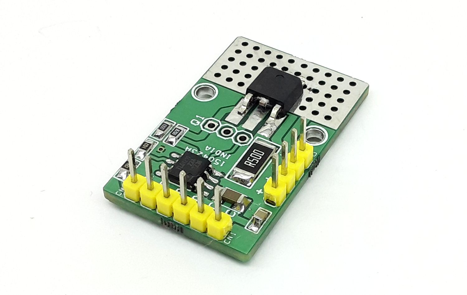
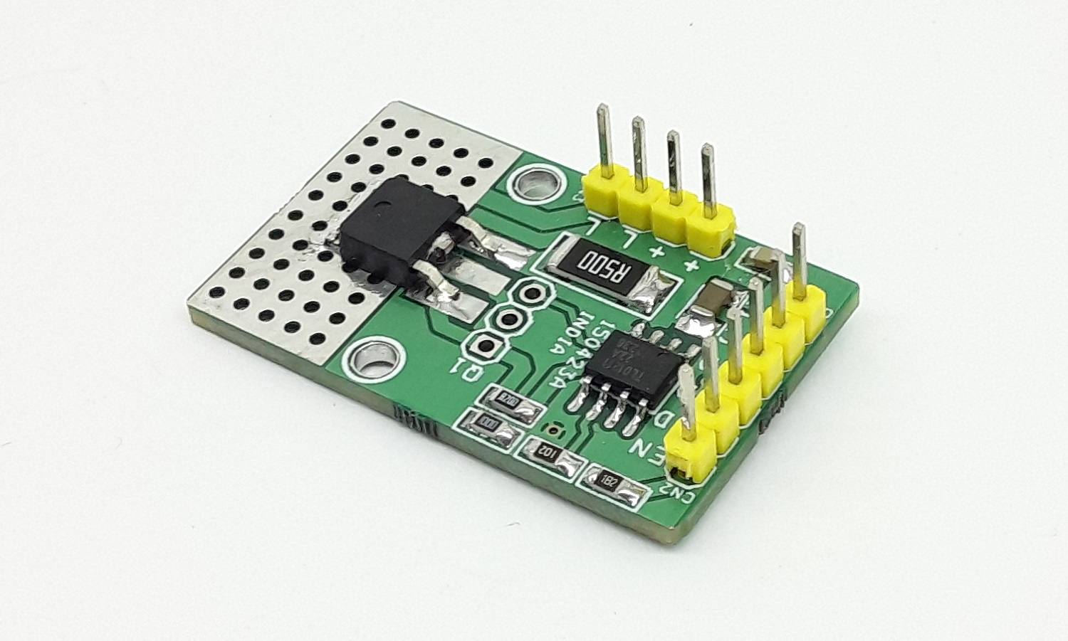
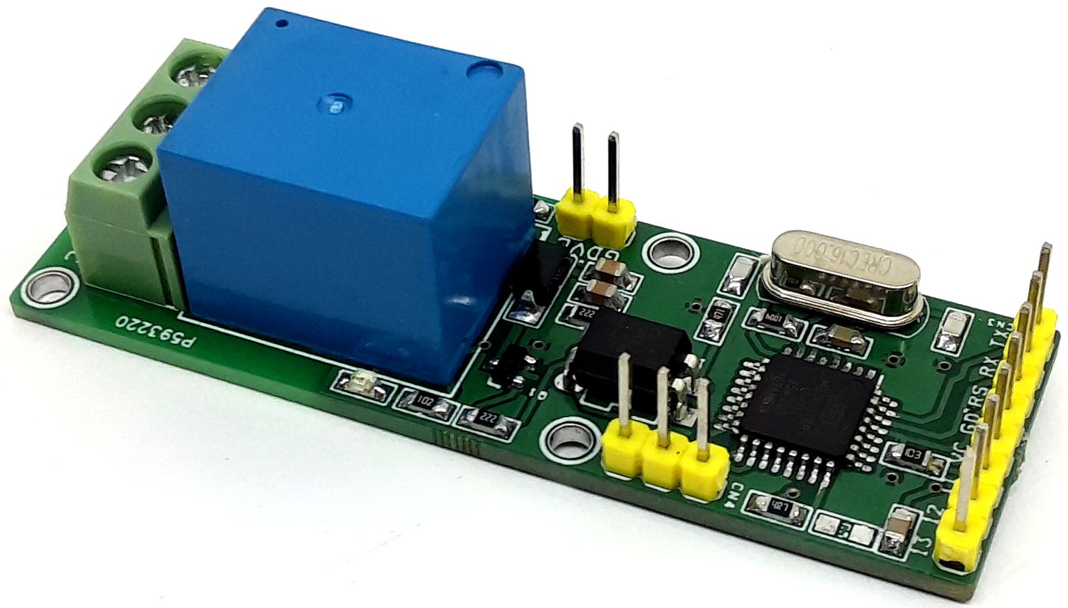
Photos
3