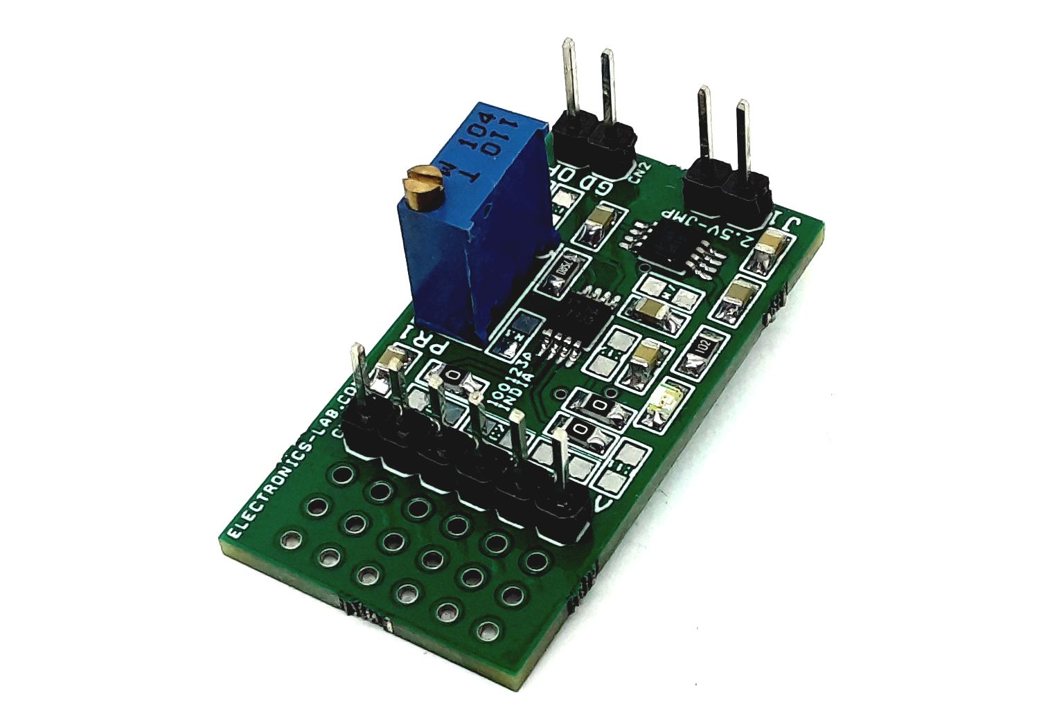
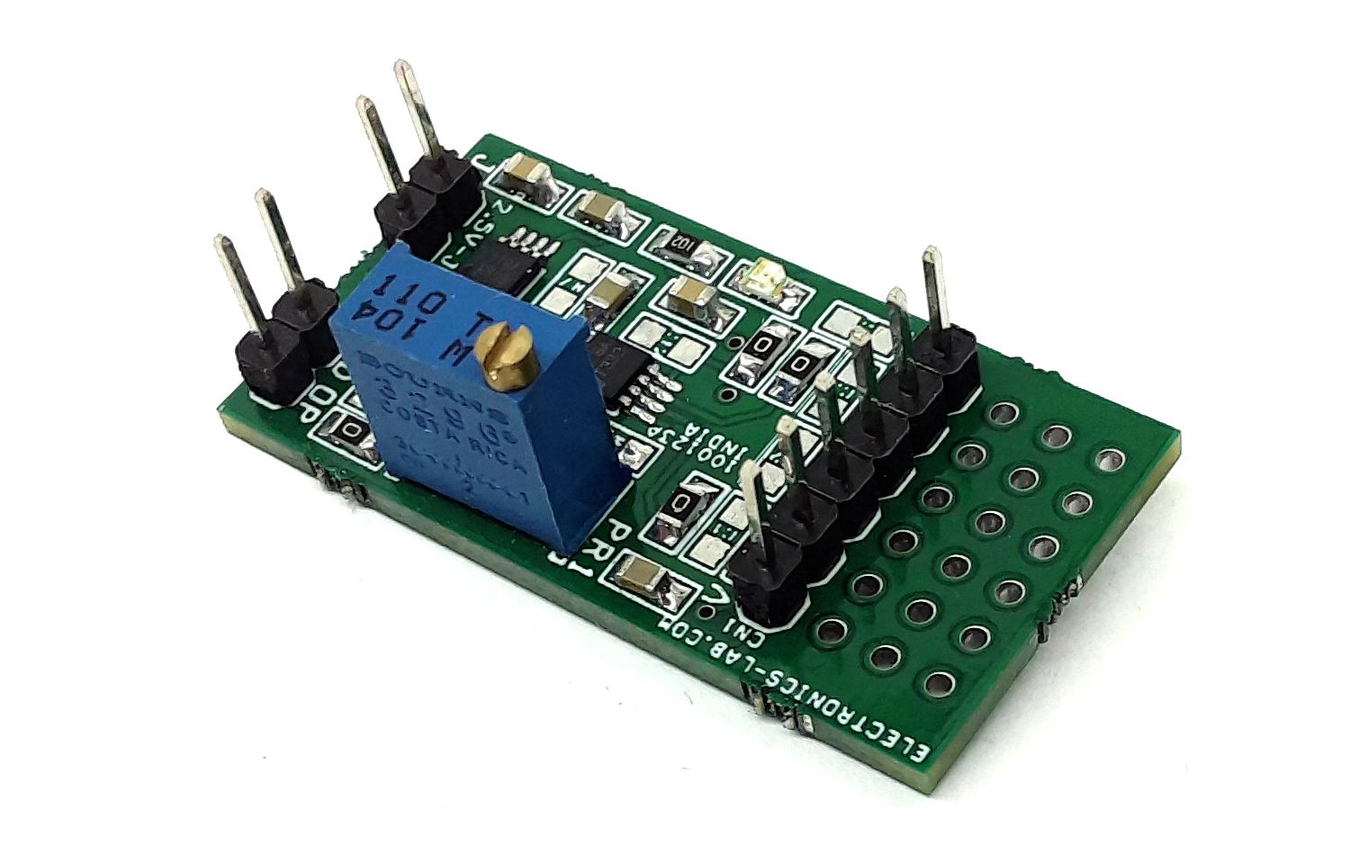
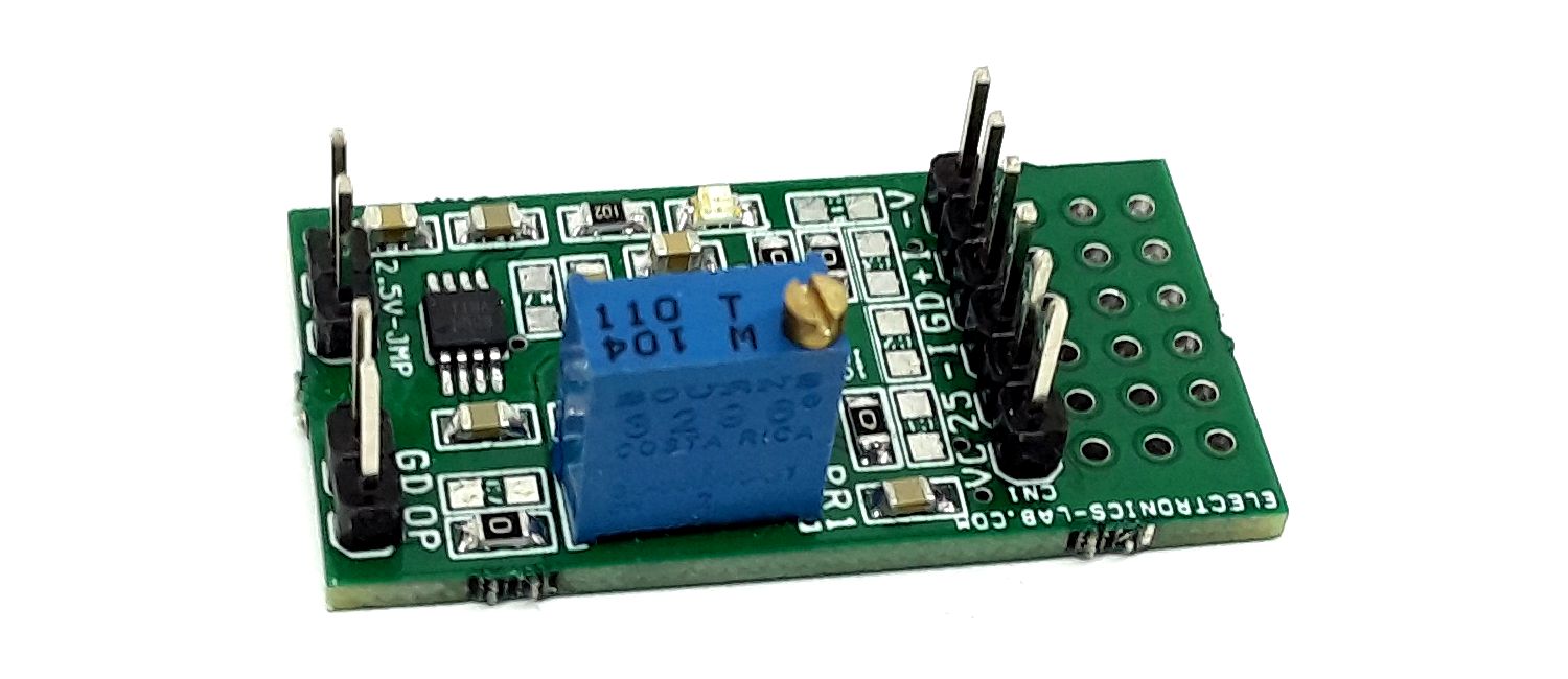
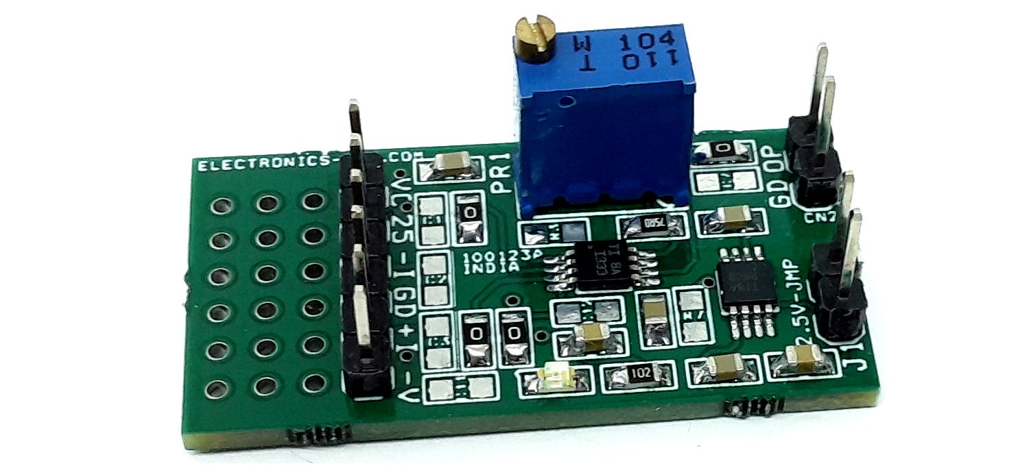
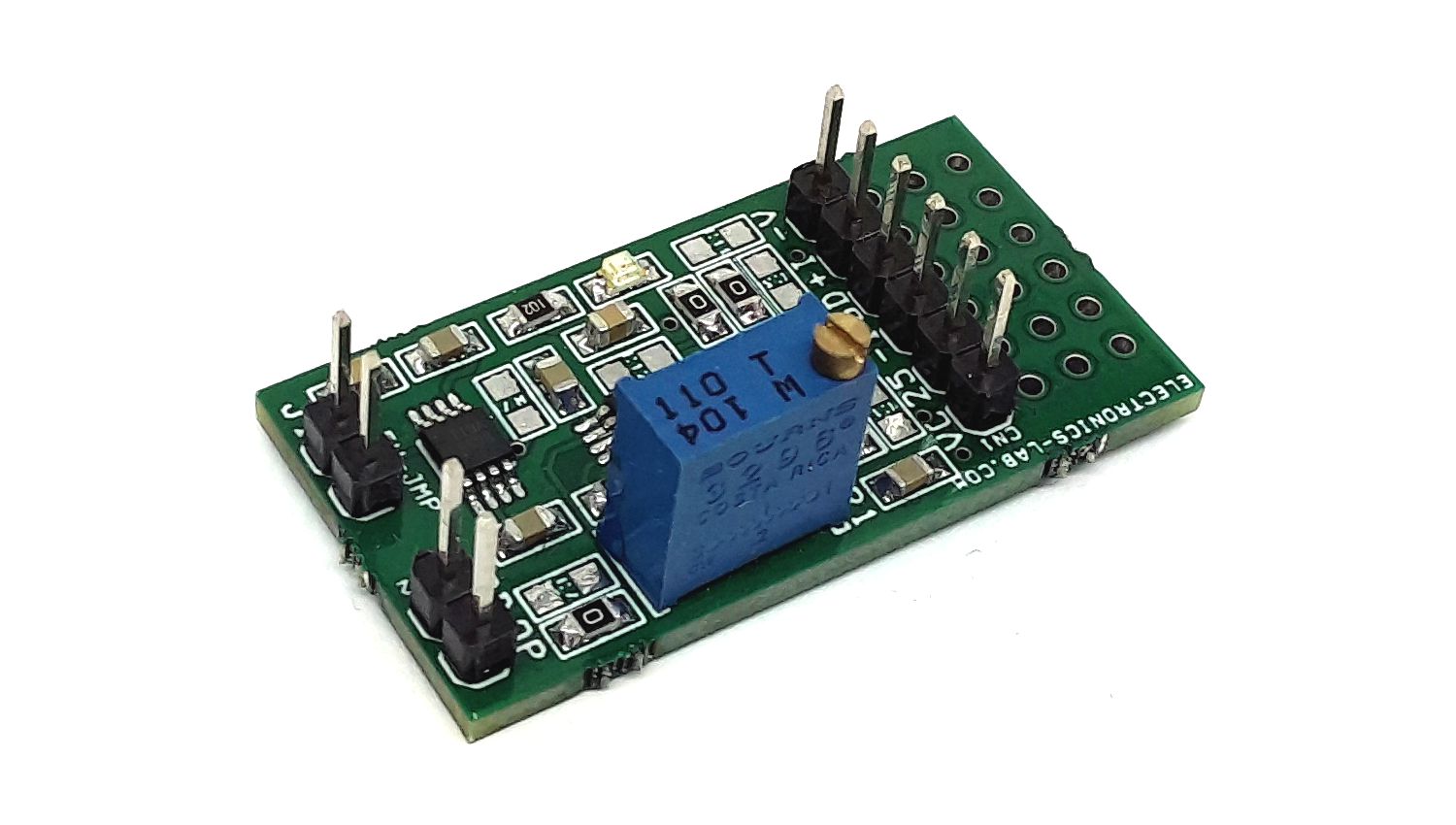
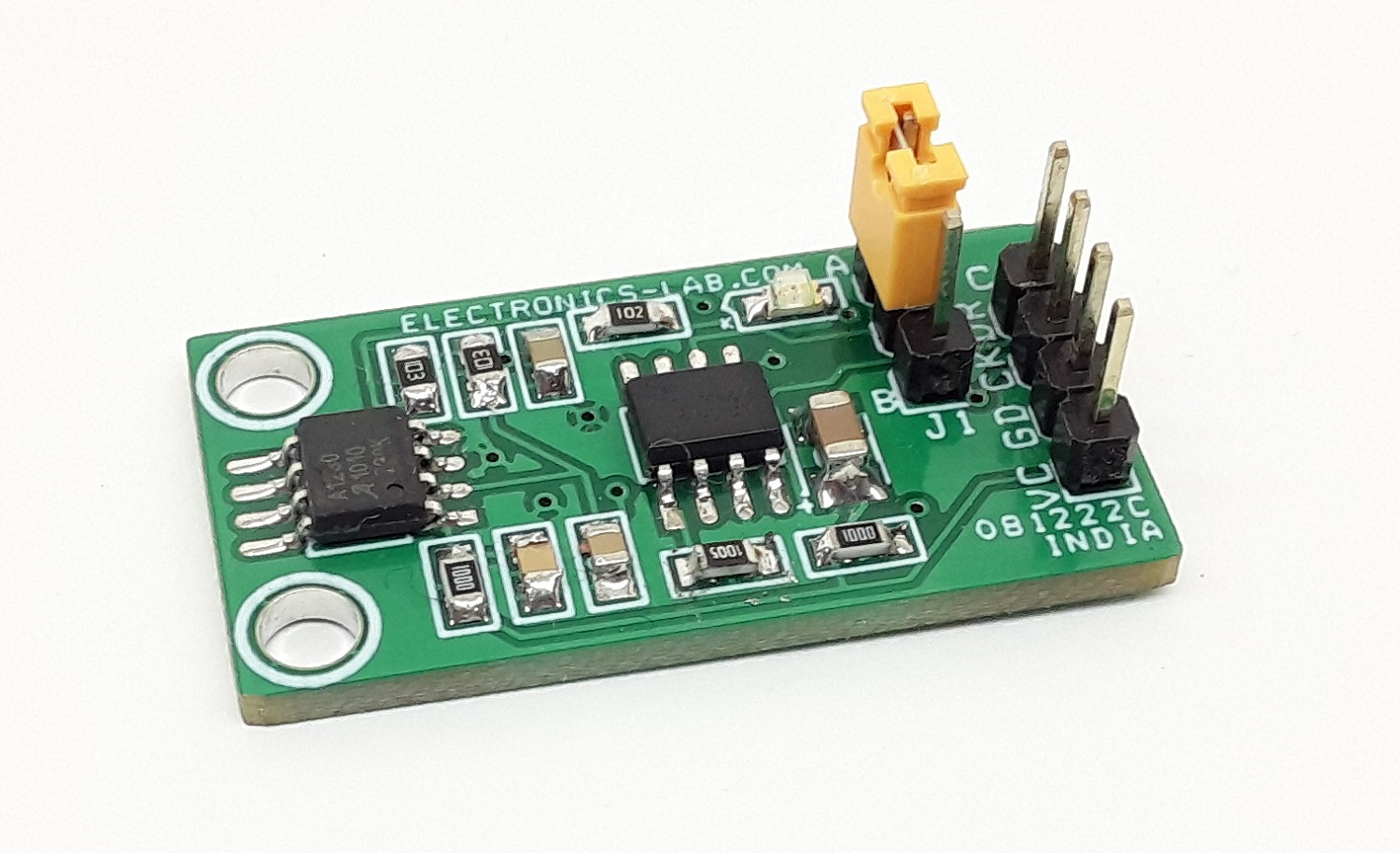
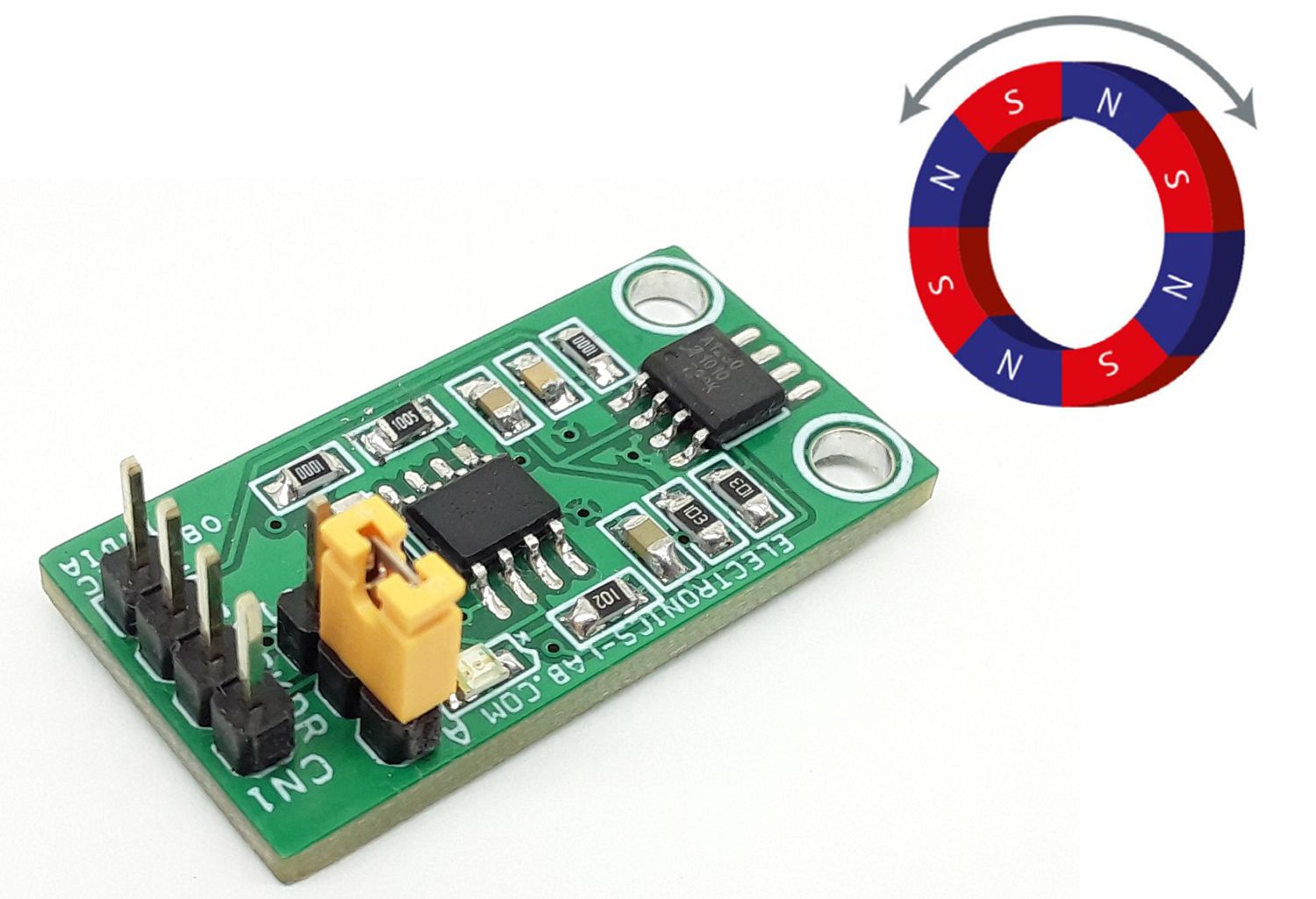
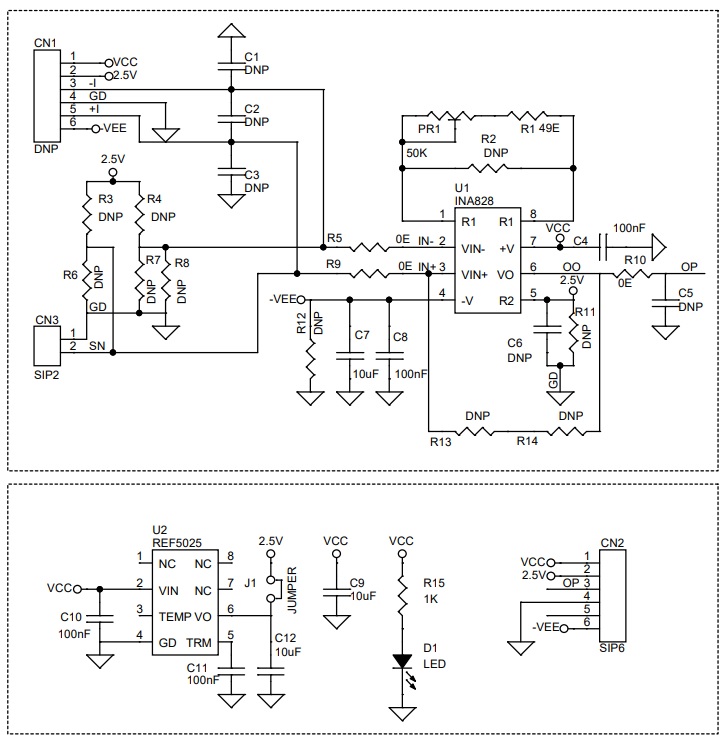
This is a universal instrumentation amplifier module for SOIC8 package. Various configurations are possible by selecting the right components. The board helps users to develop instrumentation amplifier circuits and it can accommodate SOIC8 devices such as INA828 from Texas Instruments. All capacitors are ceramic type size 0805 and resistors are also size 0805. It supports dual supply or single supply, install R12 0 Ohms for a single supply usage. Various capacitors and resistors can be installed as per application requirements. D1 is the Power LED. Board also has 2.5V precision reference voltage chip. Jumper J1 is provided to select the 2.5V reference voltage to the IN828 Amplifier. An external reference voltage can be fed through CN1 or CN2 Pin 2, Open Jumper J1 in this case. The project also consists of resistors R3, R4, R7, and R8 to create bridge configurations for various sensors. CN3 is provided for sensor input.
Features
- Single Supply: 4.5 V to 36 V, Dual Supply: ±2.25 V to ±18 V
- On Board Reference Voltage Generator Chip (Available Reference 2.5V, 5V, 1.2V)
- On Board Power LED
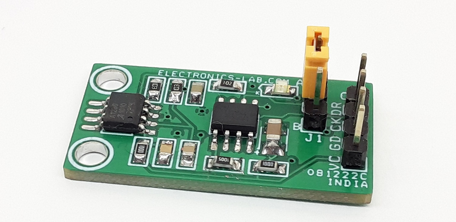
- On Board Jumper J1 for Reference Voltage Selection, External or Internal
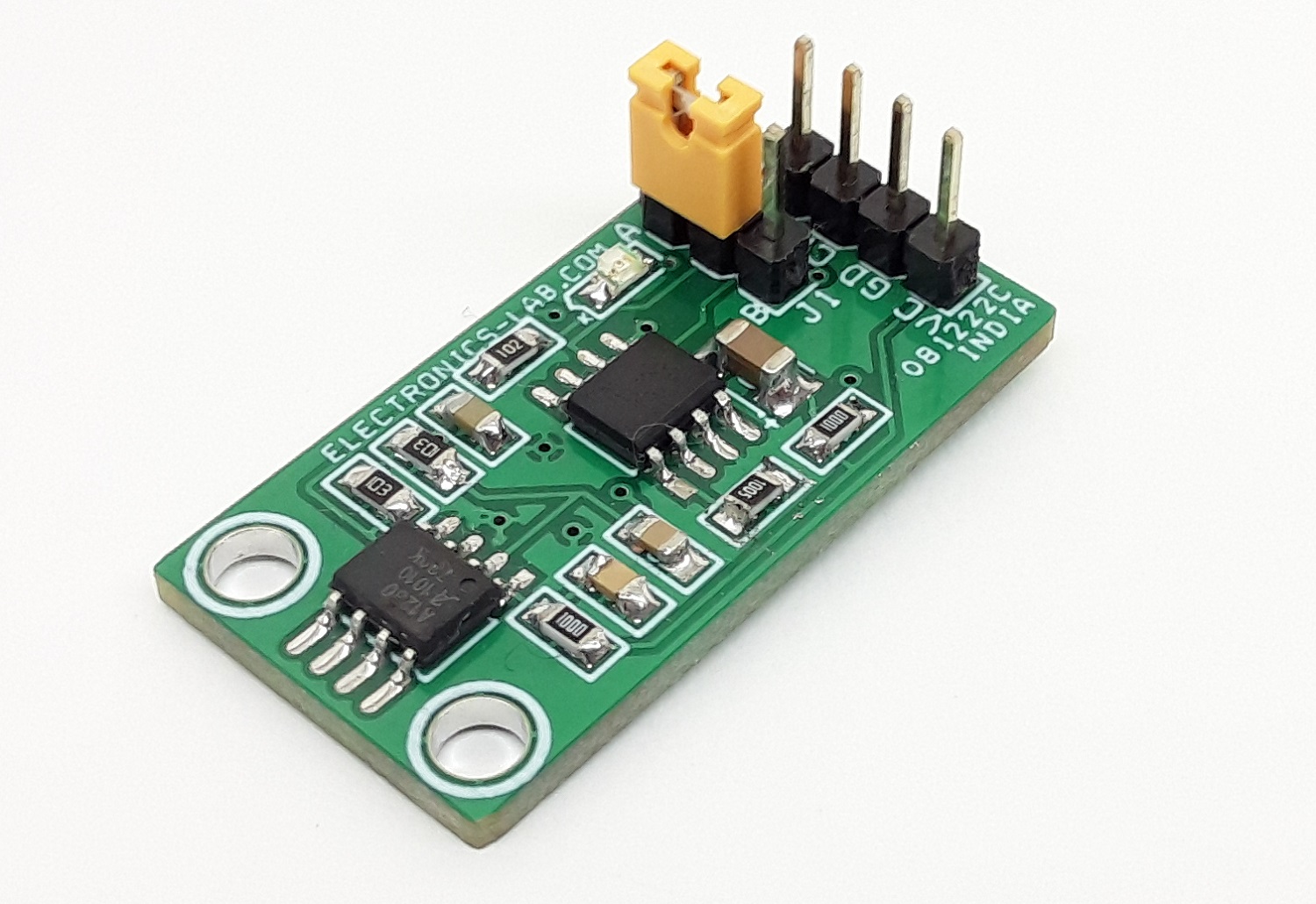
- Header Connector for Inputs, Outputs, and Supply
- Gain Adjustable 1 to 1000 Using Multiturn Trimmer Potentiometer
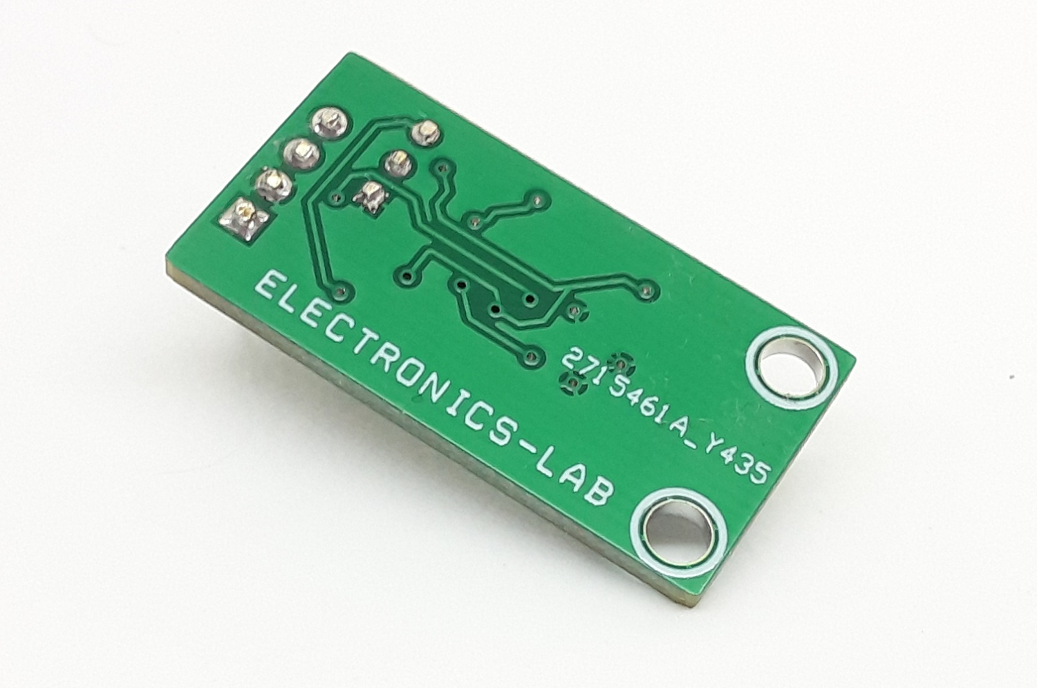
- PCB Dimensions 29.05 x 27.31 mm
Applications
- Bridge Amplifiers
- ECG Amplifiers
- Pressure Sensors
- Medical Instrumentation
- Portable Instrumentation
- Weight Scales
- Thermocouple Amplifiers
- RTD Sensor Amplifiers
- Data Acquisition
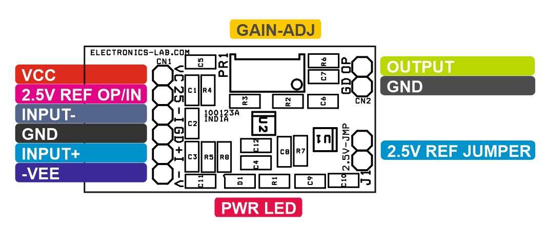
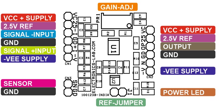
Connections and Other Details
- CN1: Pin1=VCC, Pin2=Voltage Reference 2.5V, Pin3= -Signal Input, Pin4=GND, Pin5= +Signal Input, Pin5=-VEE Supply Input
- CN2: Pin1=VCC + Supply, Pin2=Voltage Reference 2.5V, Pin3= Output, Pin4=GND, Pin5= NC, Pin5=-VEE Supply
- CN3: Sensor Input for Bridge Configuration
- PR1: Multi-Turn Potentiometer for Gain Adjust (Gain 1 to 1000)
- J1: External or Internal Reference Selection (Internal Reference 2.5V)
- D1: Power LED
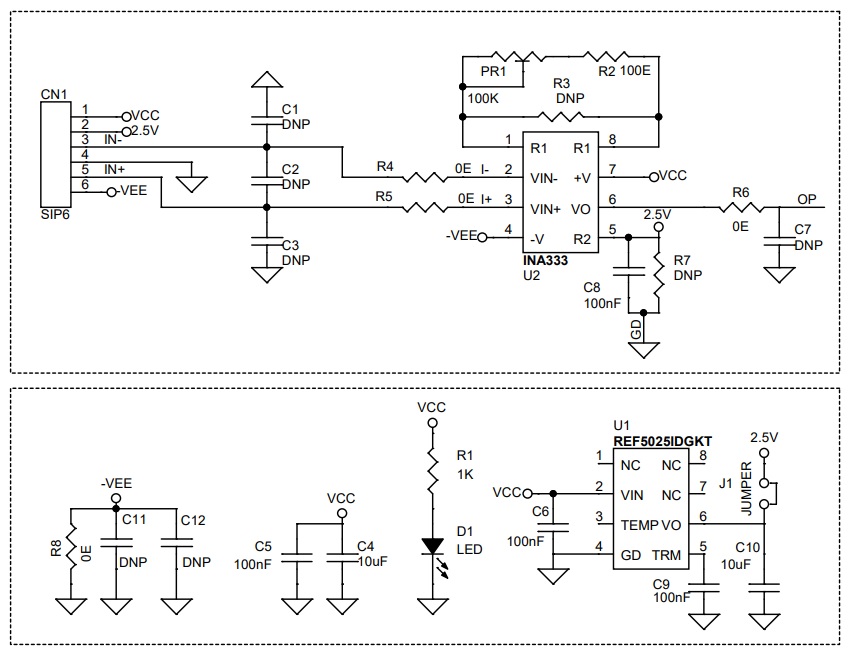
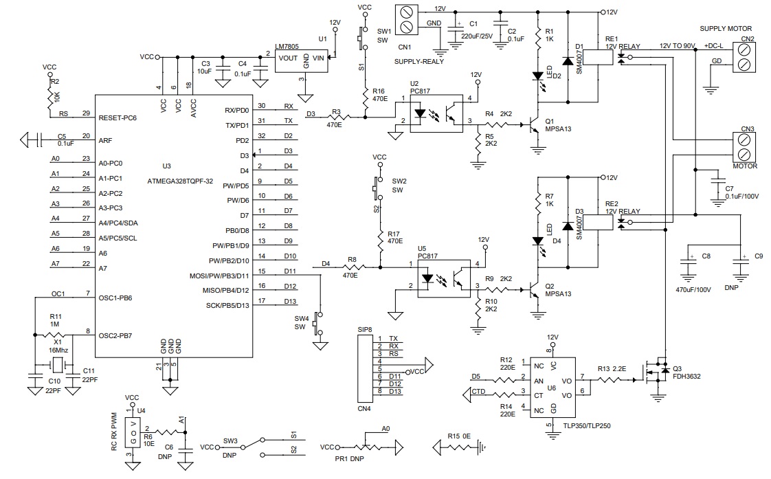
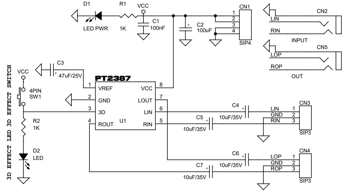
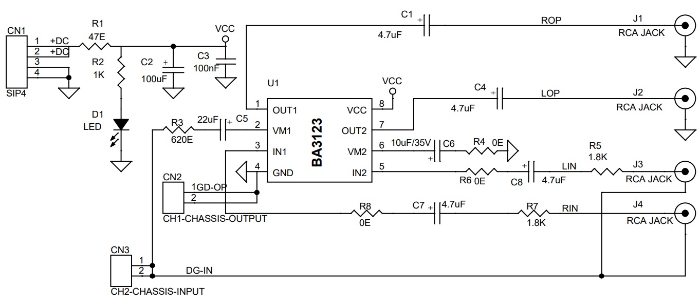
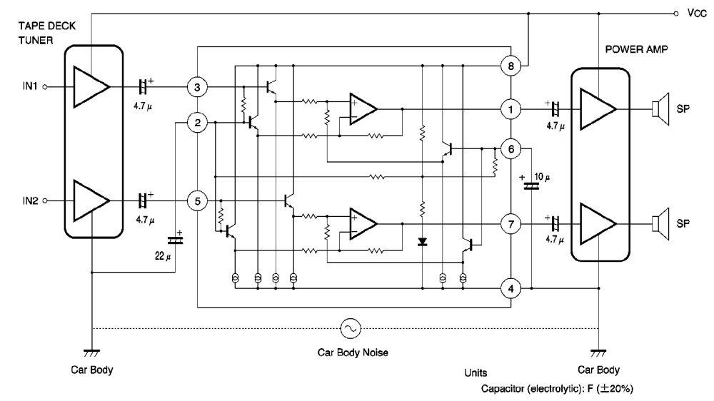
Schematic
Parts List
| NO | QNTY | REF. | DESC | MANUFACTURER | SUPPLIER | SUPPLIER PART NO |
|---|---|---|---|---|---|---|
| 1 | 1 | CN1,CN2 | 6 PIN MALE HEADER PITCH 2.54MM | WURTH | DIGIKEY | 732-5319-ND |
| 2 | 2 | CN3 | 2 PIN MALE HEADER PITCH 2.54MM | WURTH | DIGIKEY | 732-5315-ND |
| 3 | 13 | R1,R3,R4,C1,R2,C2,C3,C5,R6,C6,C8,R11,R12,R13,R14,R8 | DNP/AS PER USER REQUIRMENT | DIGIKEY | ||
| 4 | 5 | C4,C8,C9,C10,C11 | 100nF/50V CERAMIC SMD SIZE 0805 | YAGEO/MURATA | DIGIKEY | |
| 5 | 1 | SHUNT FOR JUMPER-J1 | SHUNT | SULLINS CONNCT | DIGIKEY | S9001-ND |
| 6 | 2 | C7,C12 | 10uF/25V CERAMIC SMD SIZE 0805 | YAGEO/MURATA | DIGIKEY | |
| 7 | 1 | D1 | LED RED SMD SIZE 0805 | OSRAM | DIGIKEY | 475-1278-1-ND |
| 8 | 1 | J1 | JUMPER/2PIN MALE HEADER 2.54MM | WURTH | DIGIKEY | 732-5315-ND |
| 9 | 1 | PR1 | 50K MULTI TURN POT | BOURNS | DIGIKEY | 3296W-503LF-ND |
| 10 | 3 | R5,R9,R10 | 0E SMD SIZE 0805 | YAGEO/MURATA | DIGIKEY | |
| 11 | 1 | R1 | 49.9E 1% SMD SIZE 0805 | YAGEO/MURATA | DIGIKEY | |
| 12 | 1 | R15 | 1K 5% SMD SIZE 0805 | YAGEO/MURATA | DIGIKEY | |
| 13 | 1 | U1 | INA828 SOIC8 | TI | DIGIKEY | 296-48914-1-ND |
| 14 | 1 | U2 | REF5025 VSSOP8 | TI | DIGIKEY | 296-24499-1-ND |
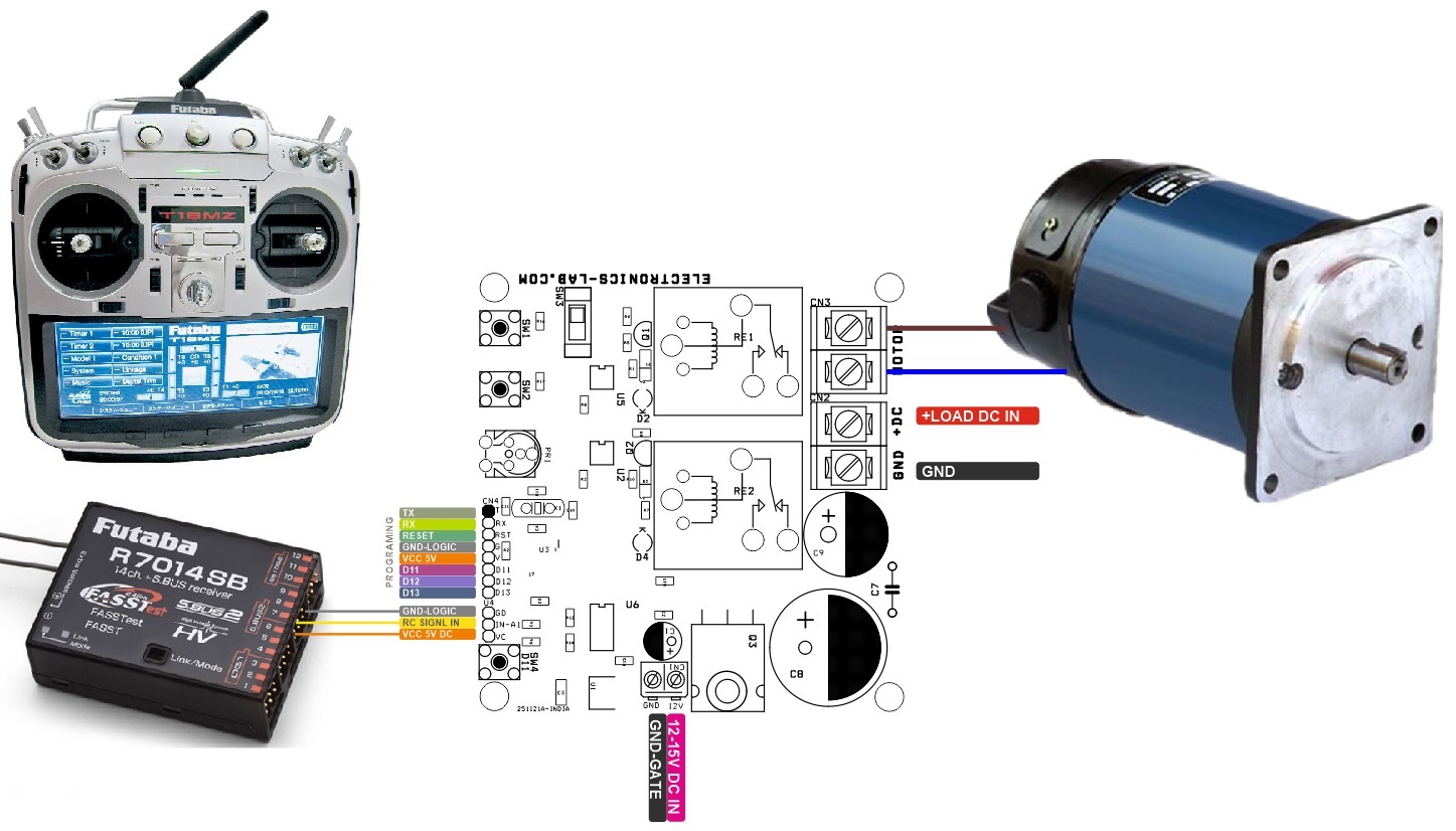
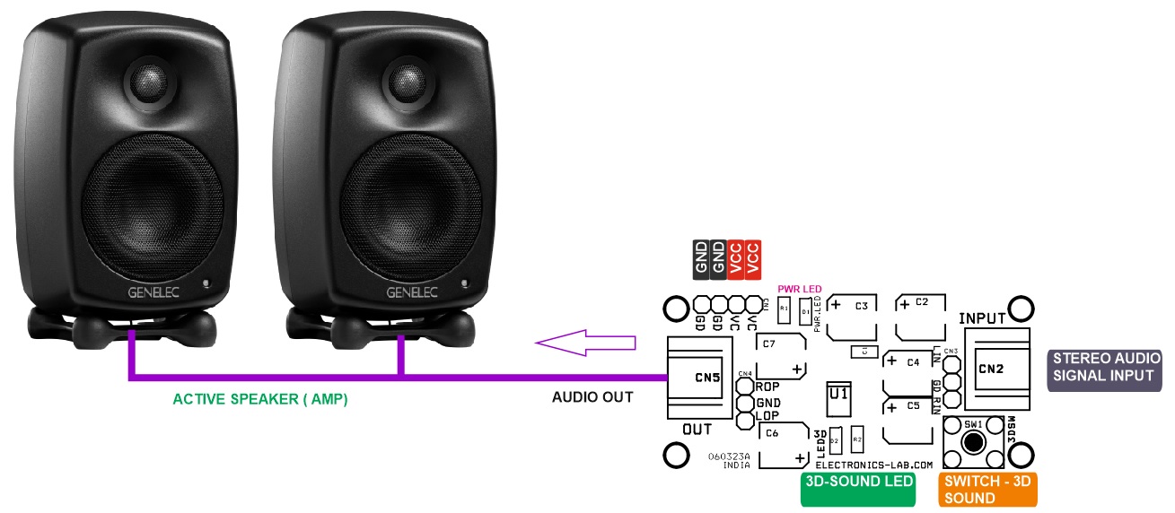
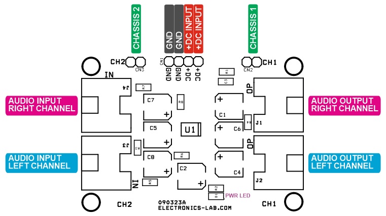
Connections
Gerber View
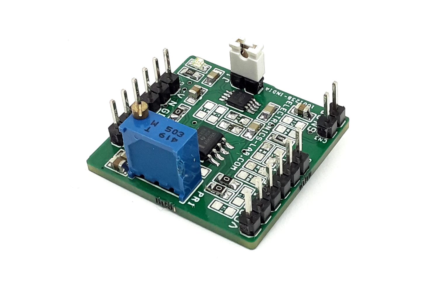
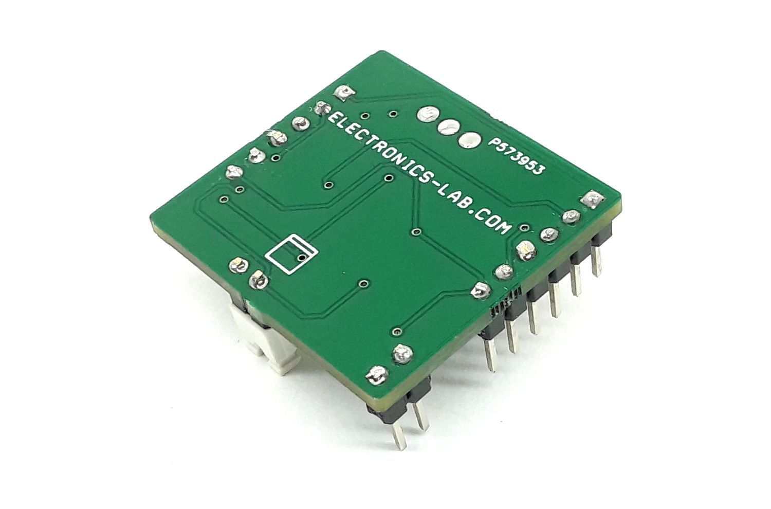
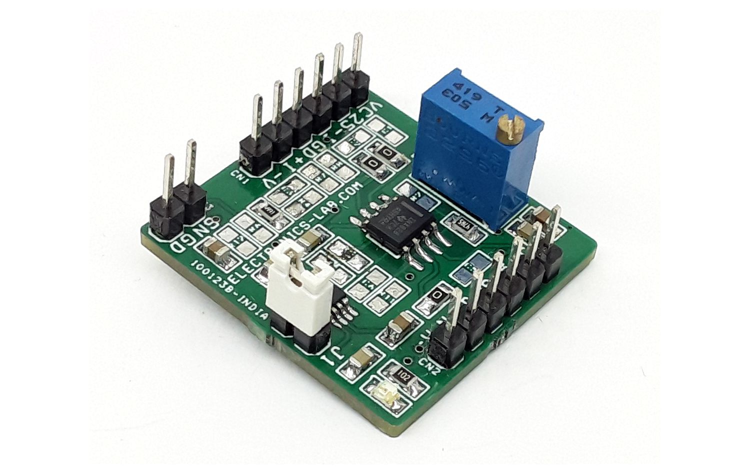
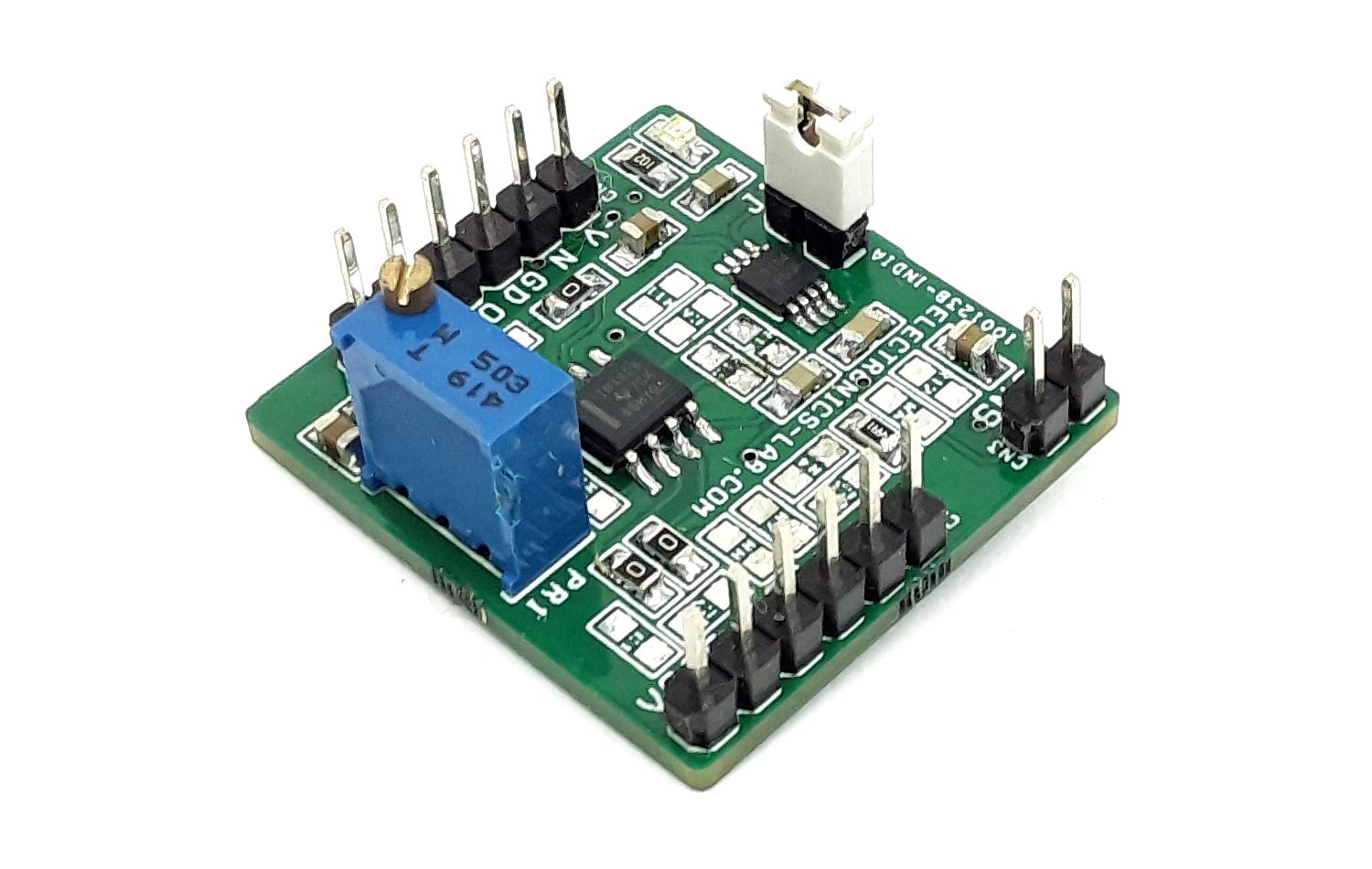
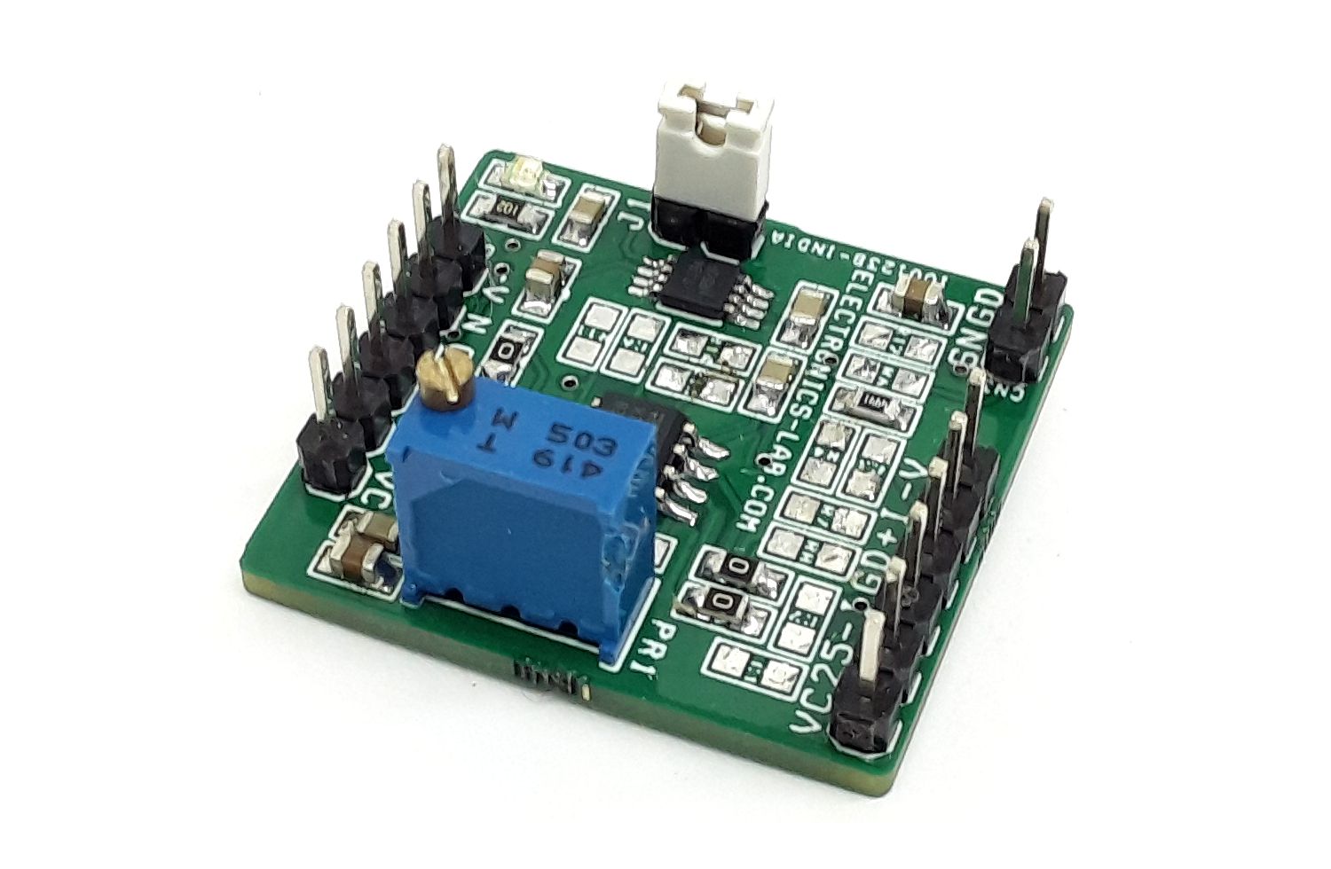
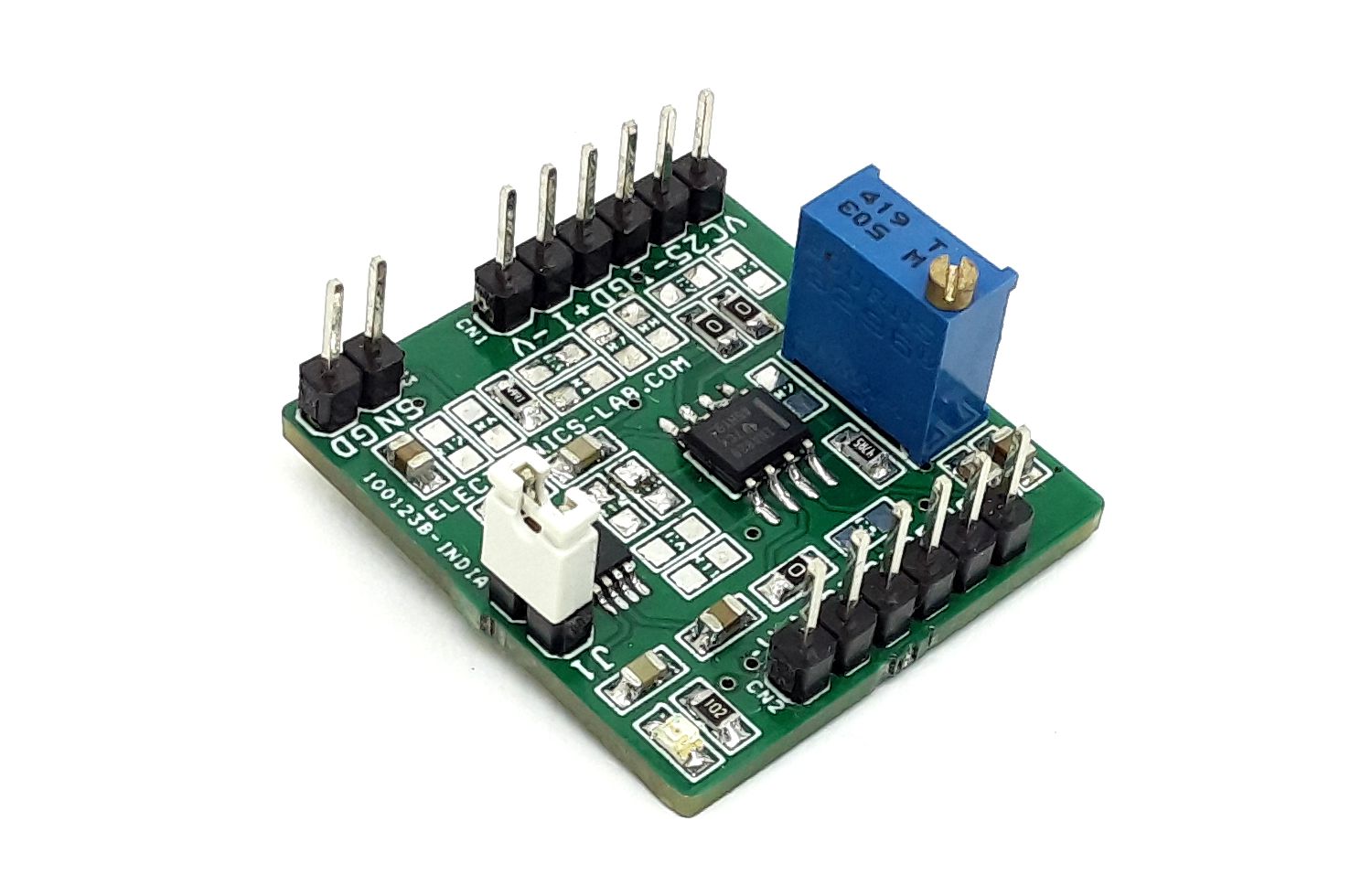
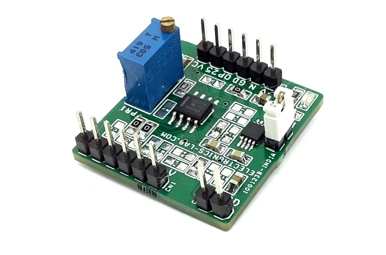
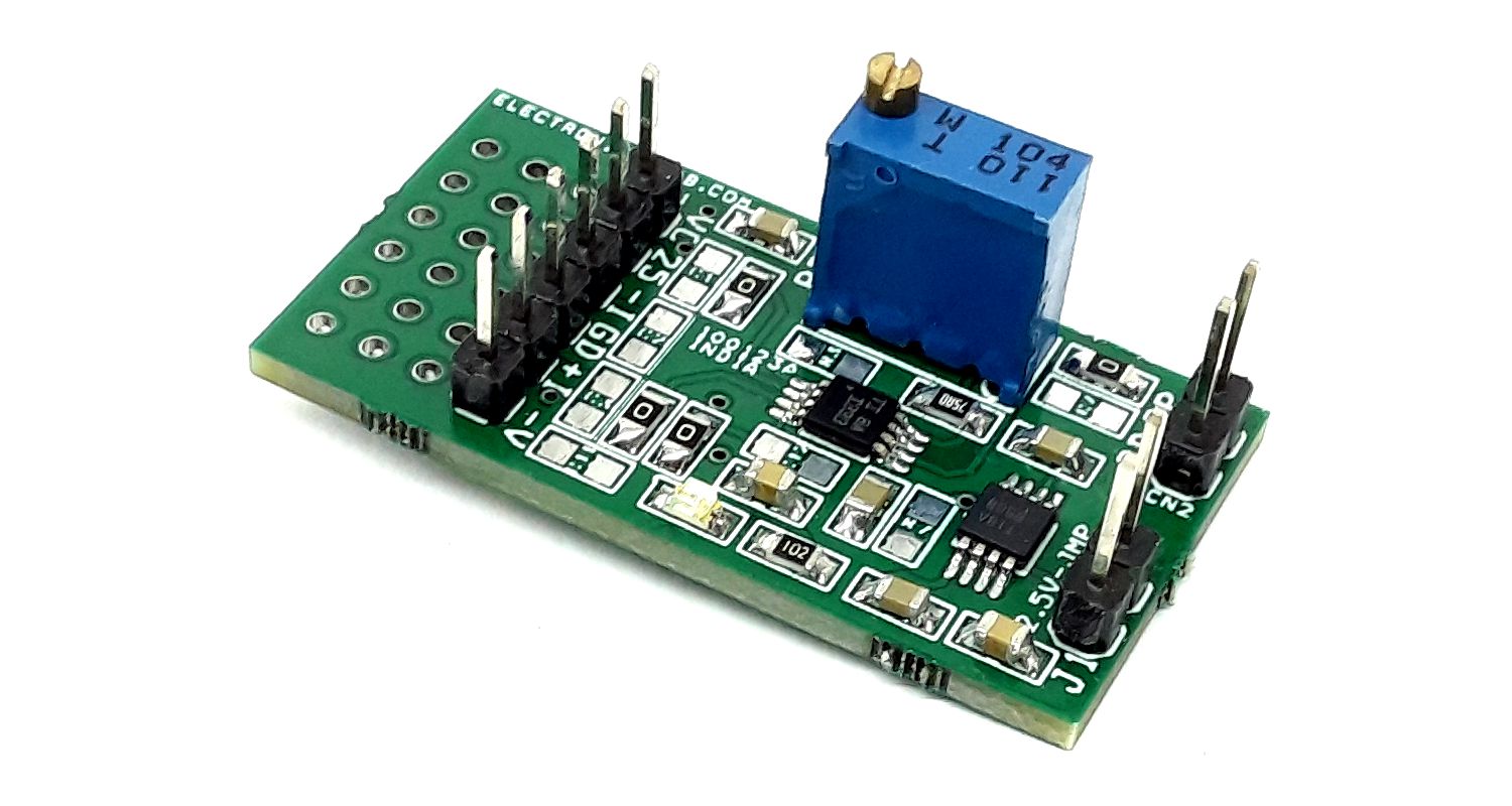
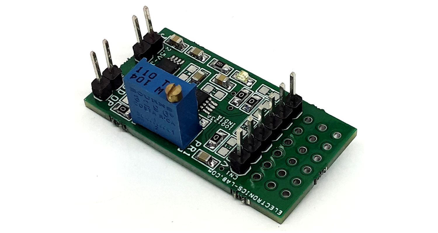
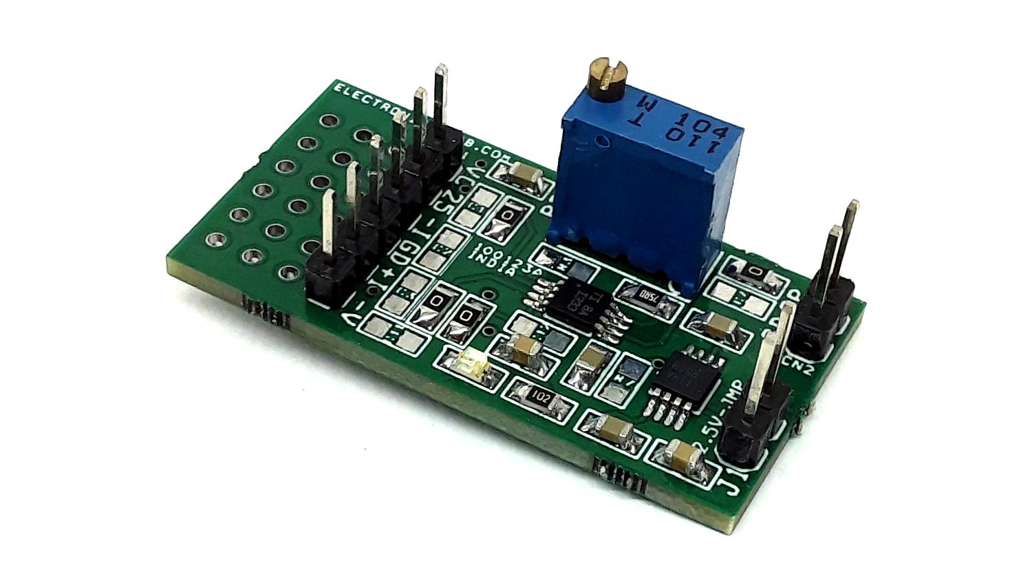
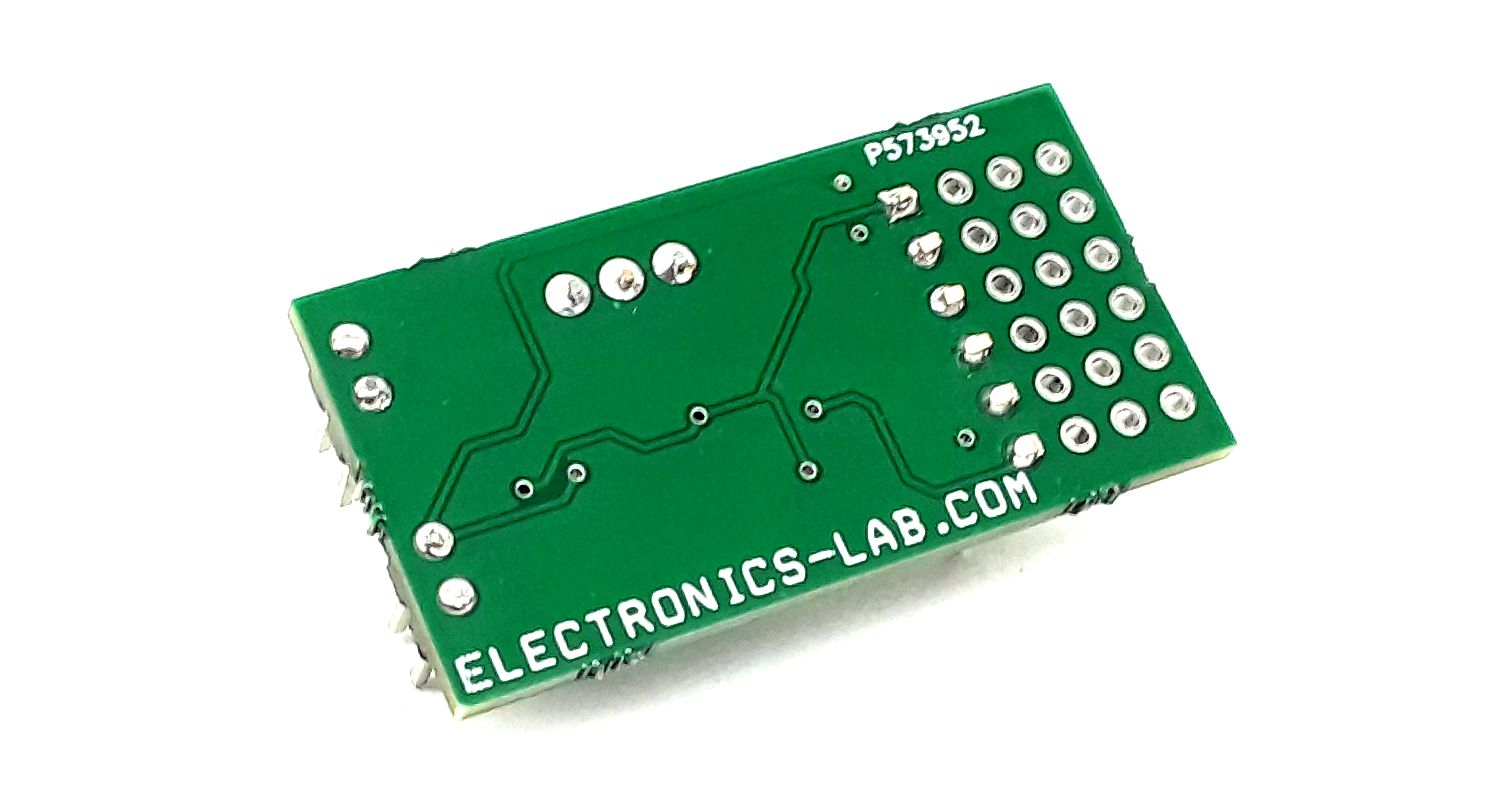
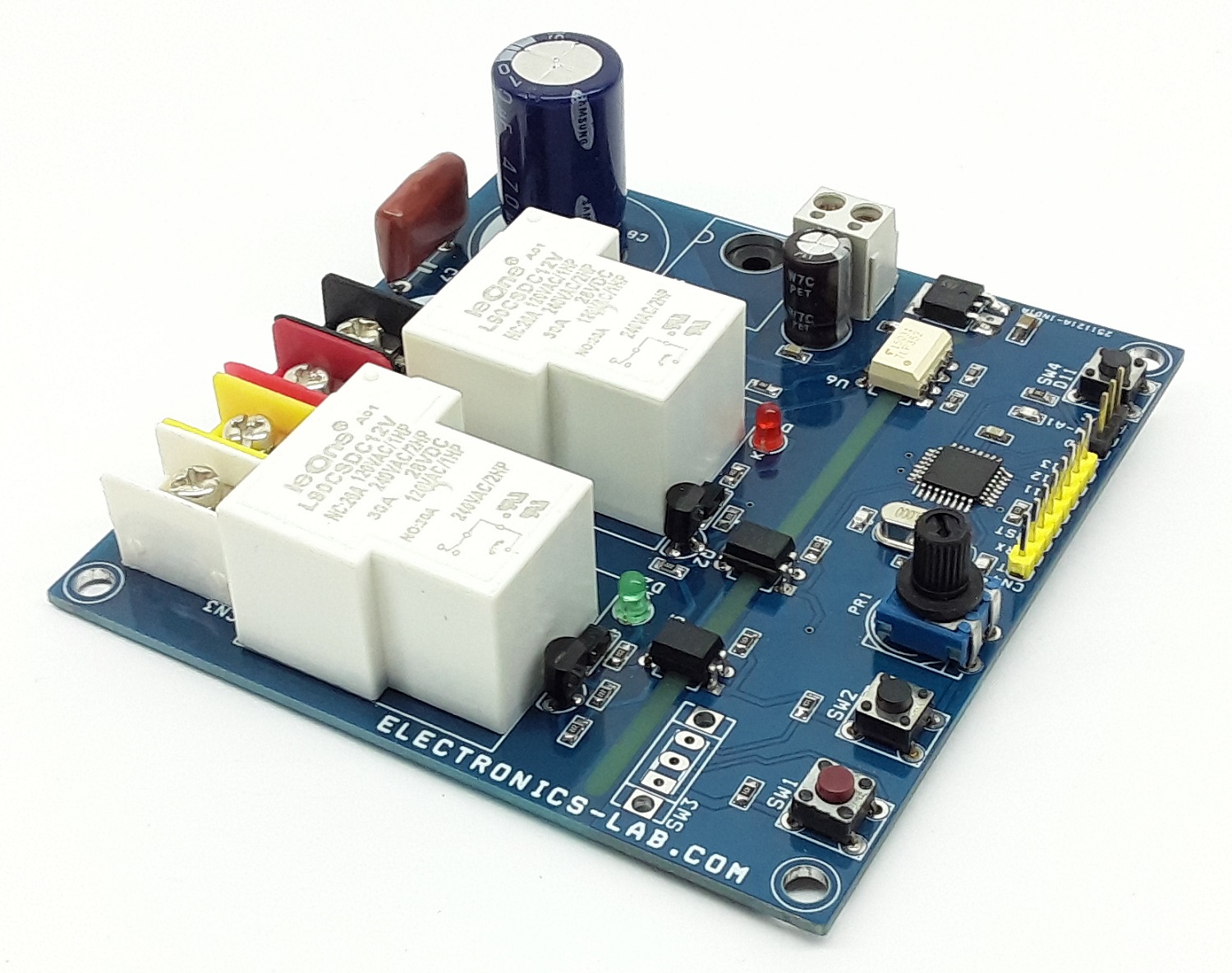
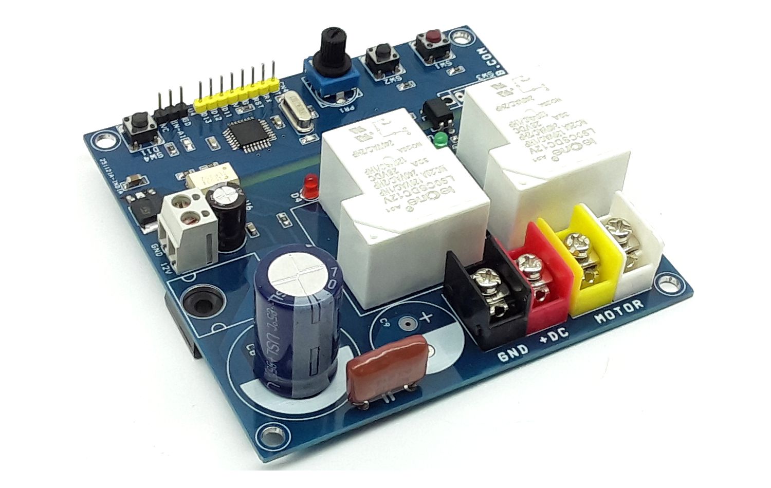
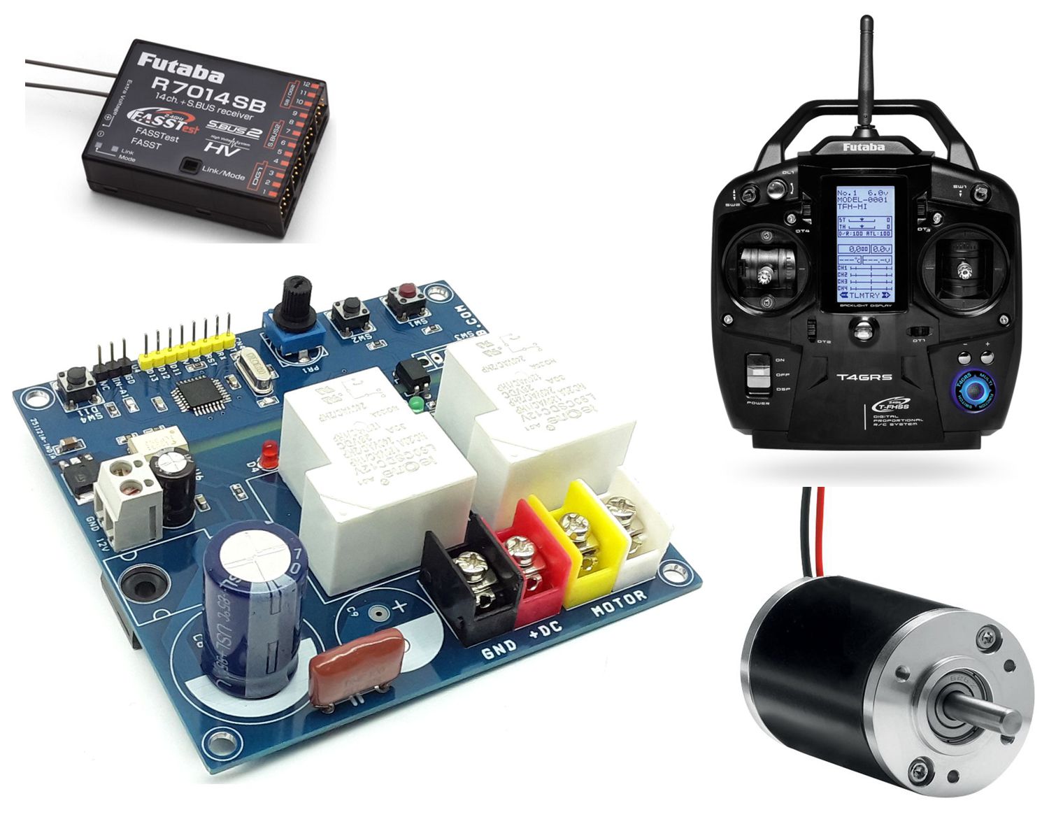
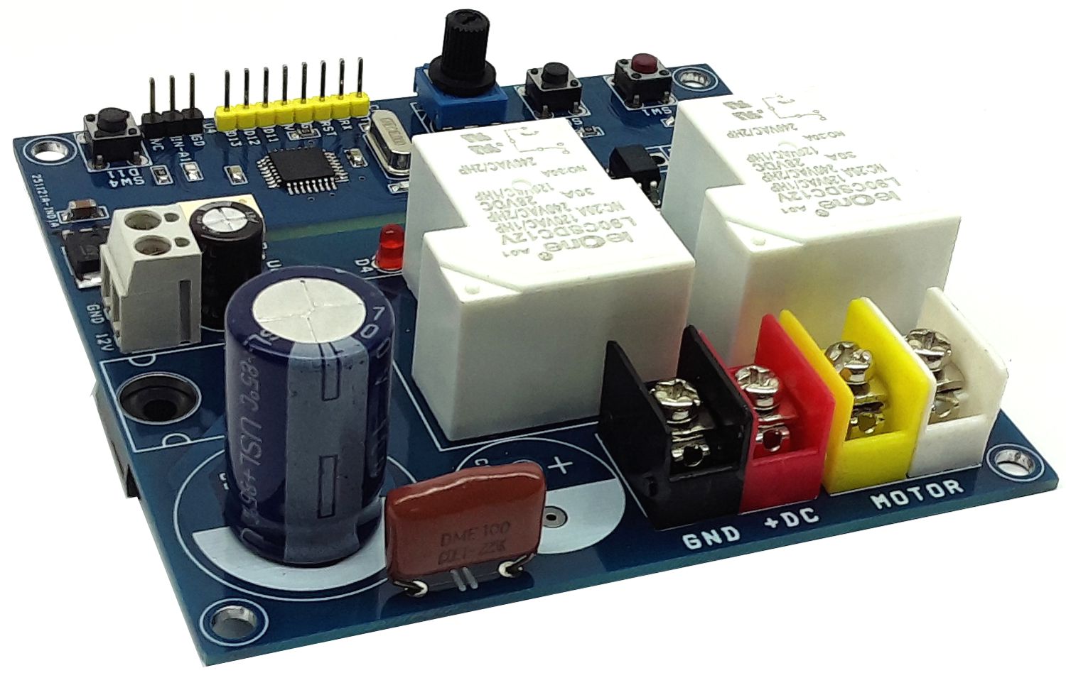
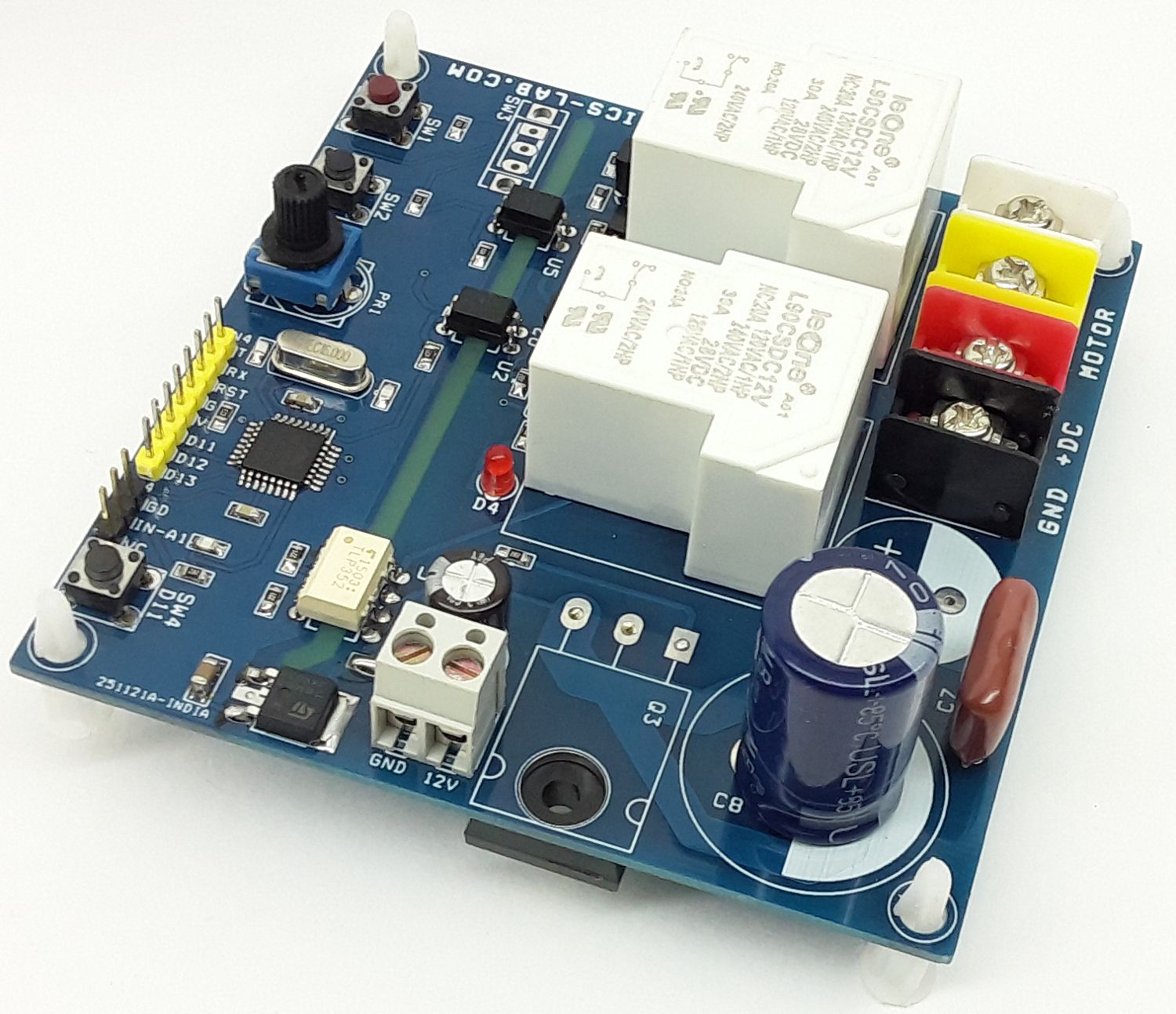
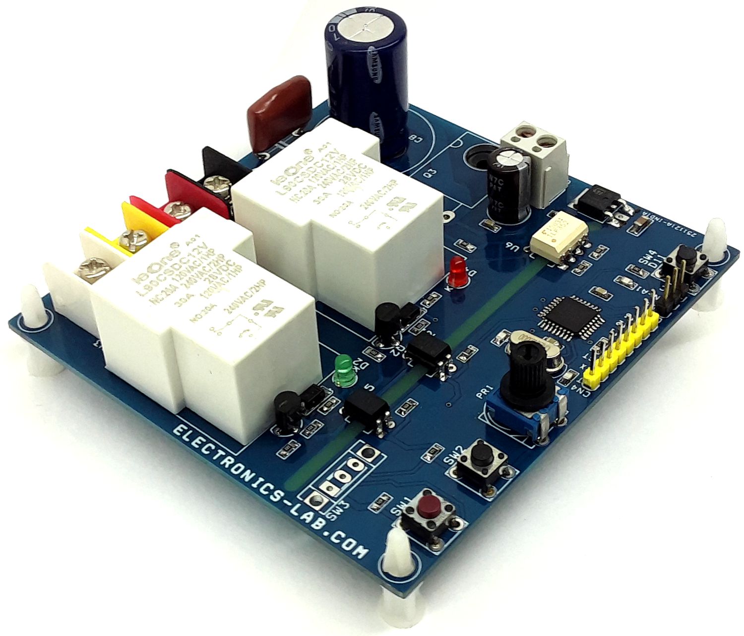
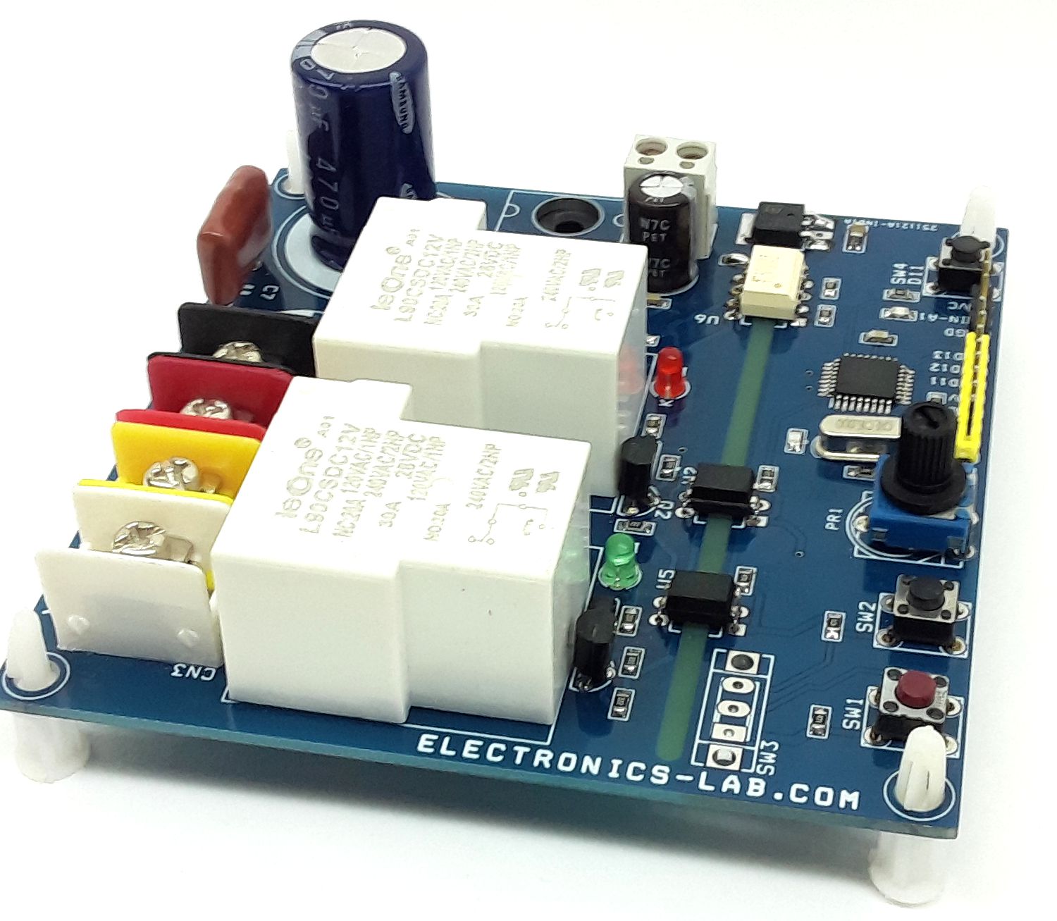
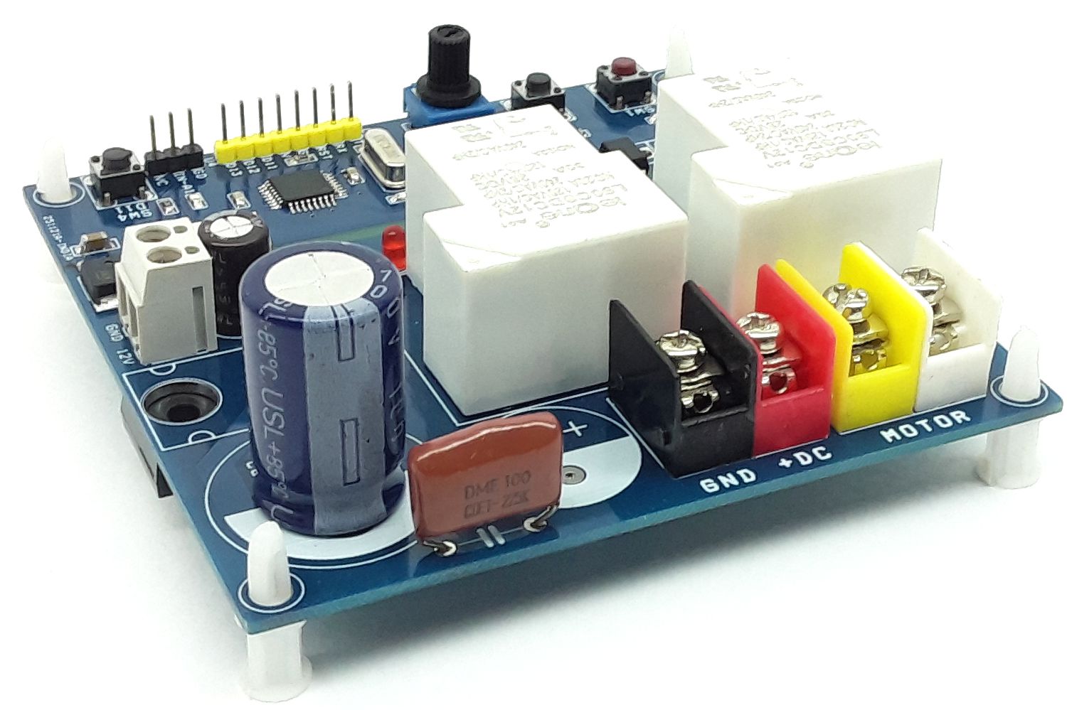
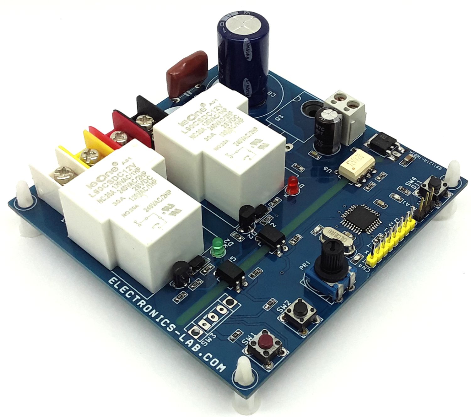
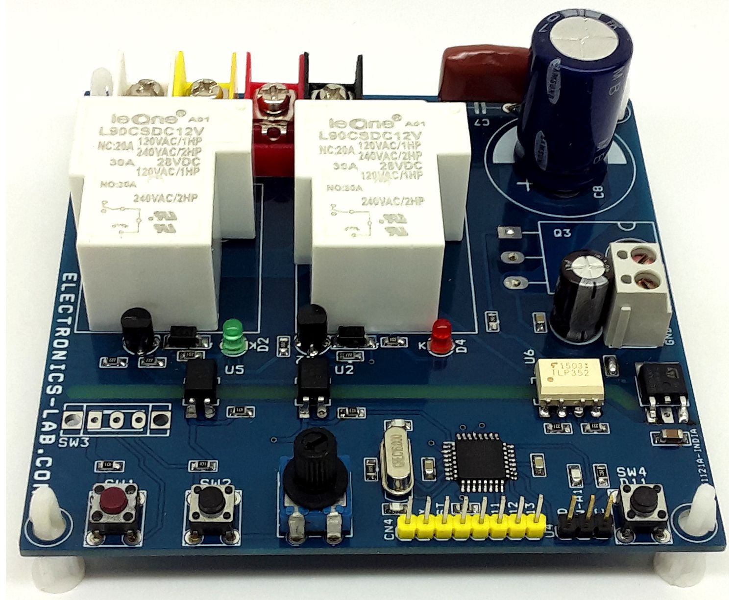
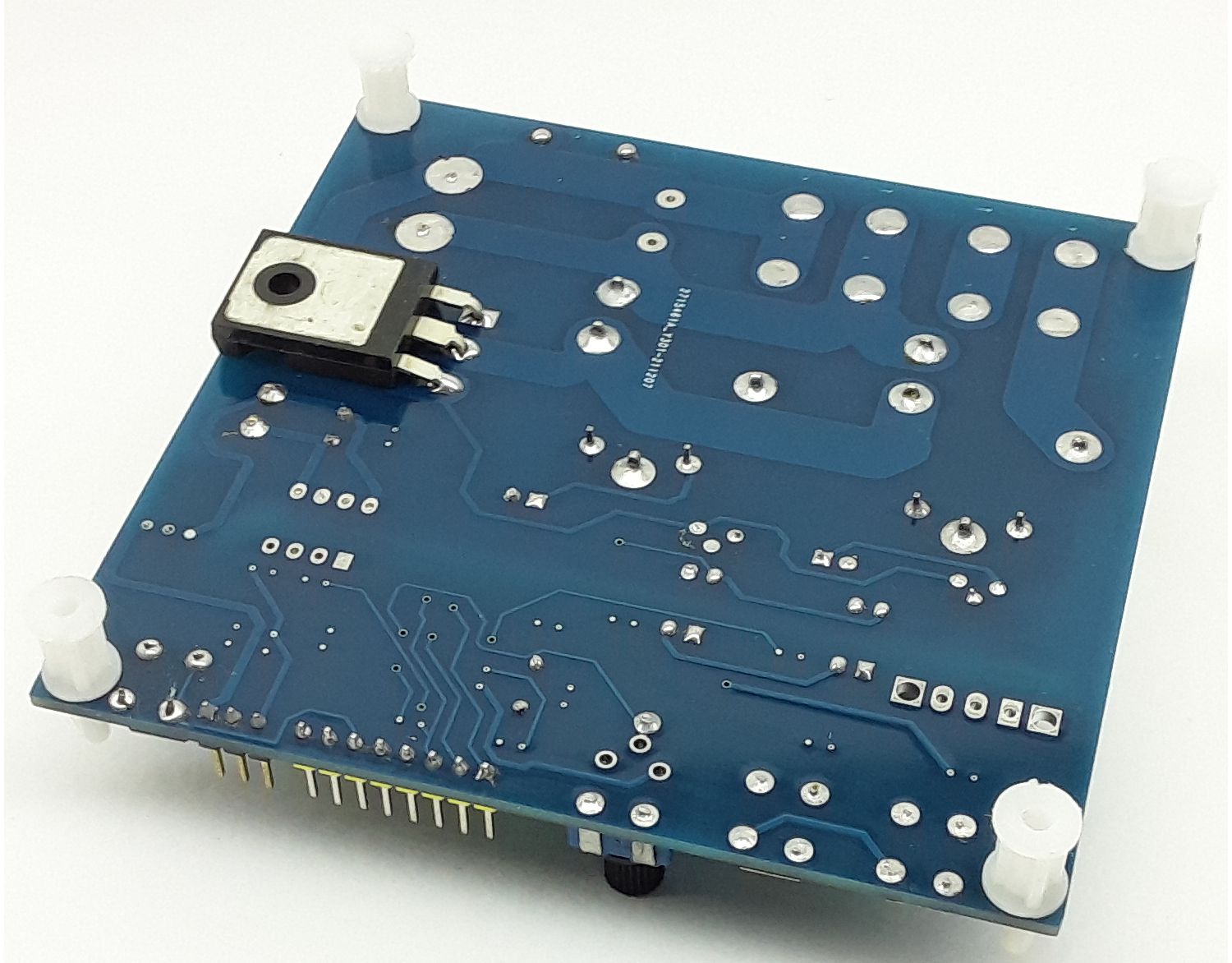
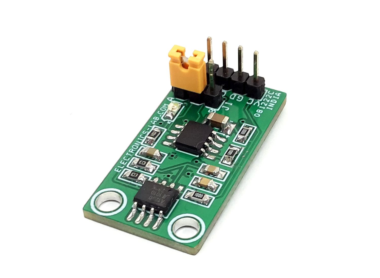
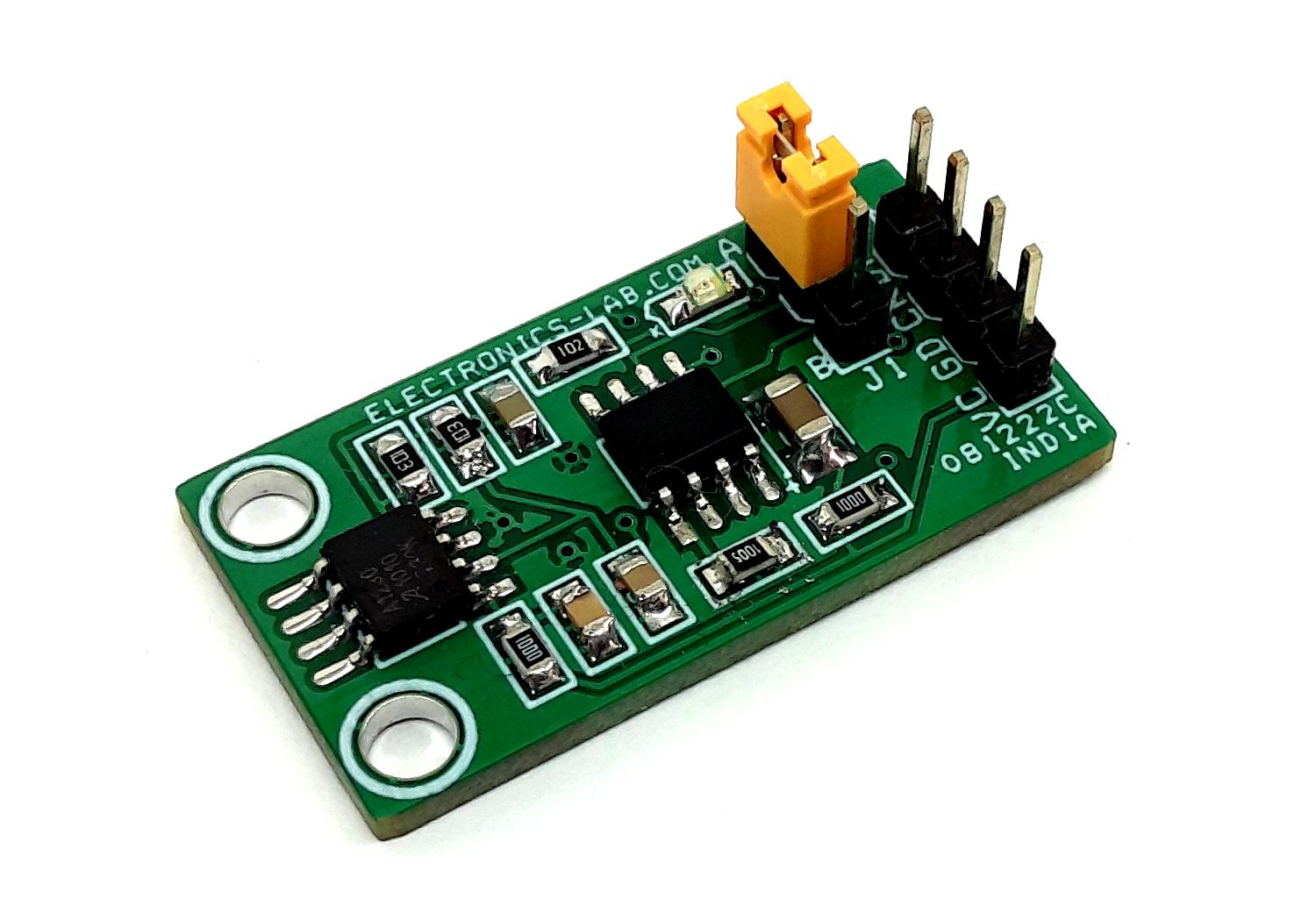
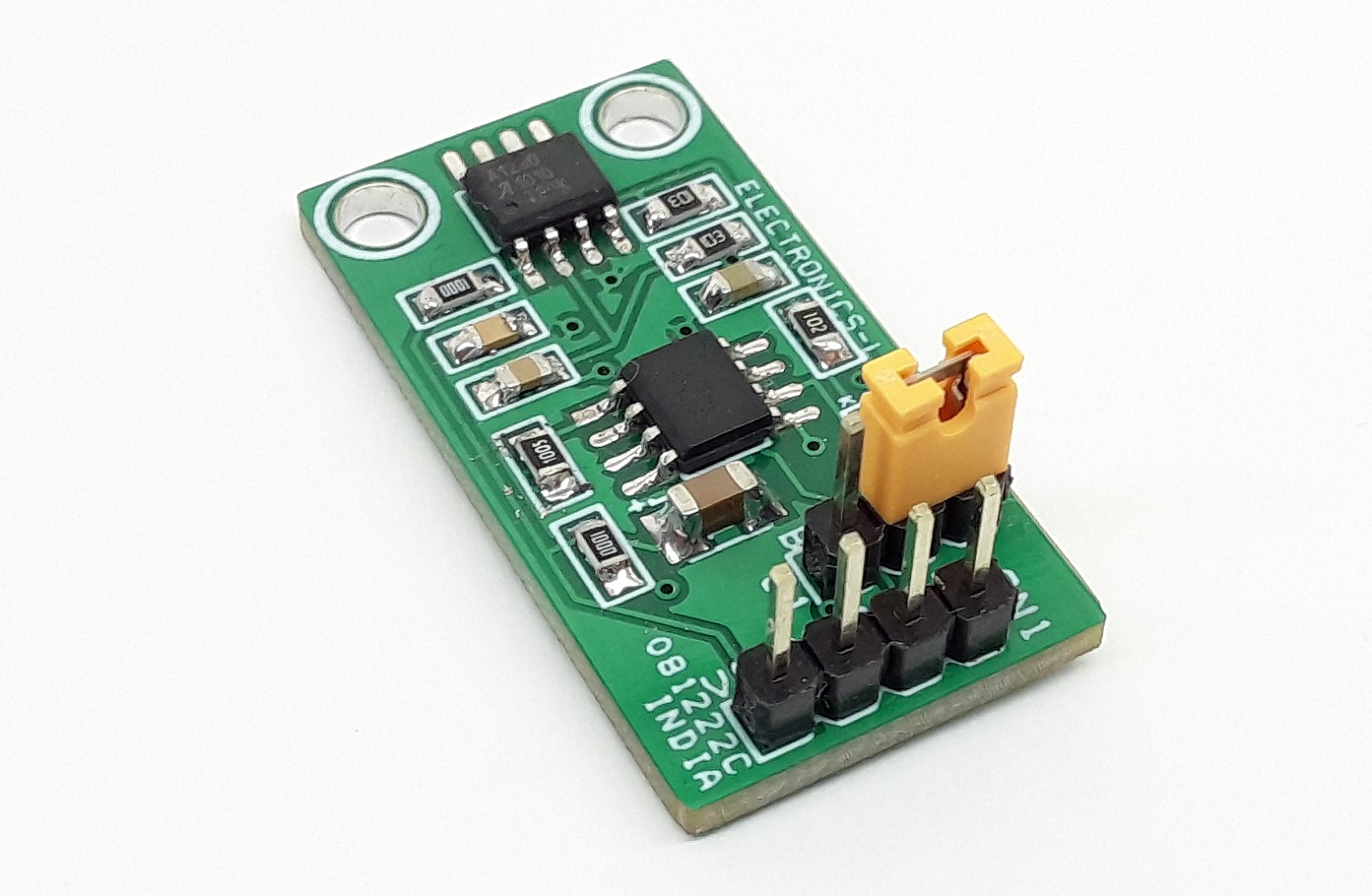
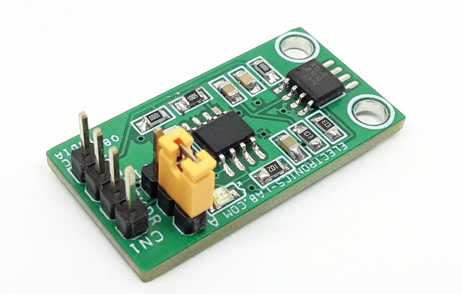
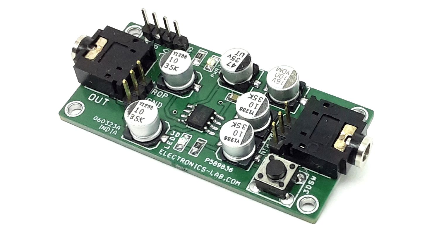
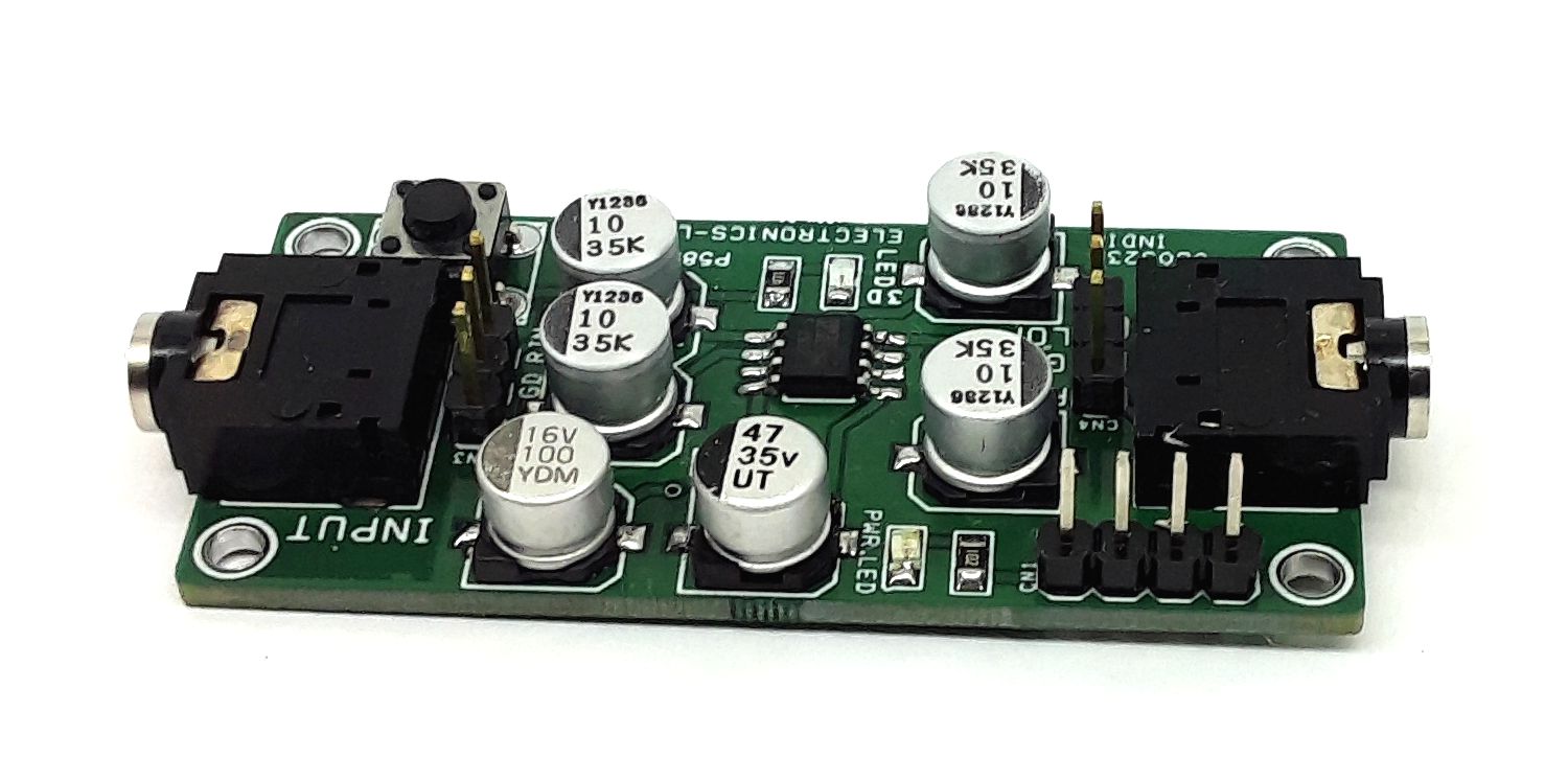
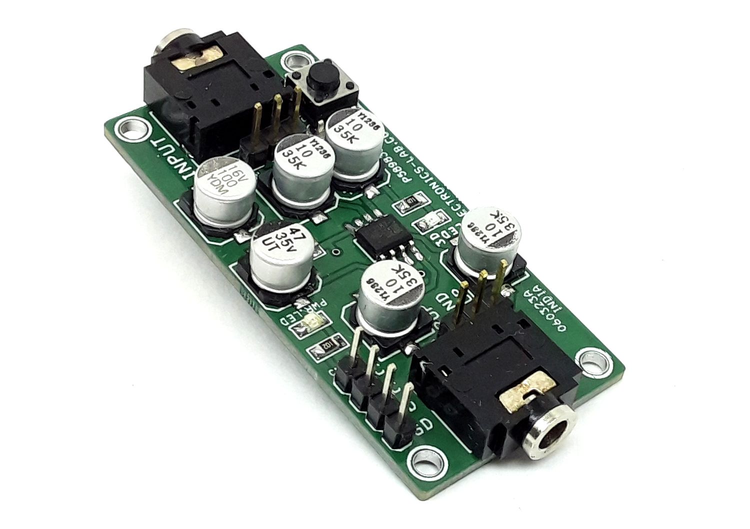
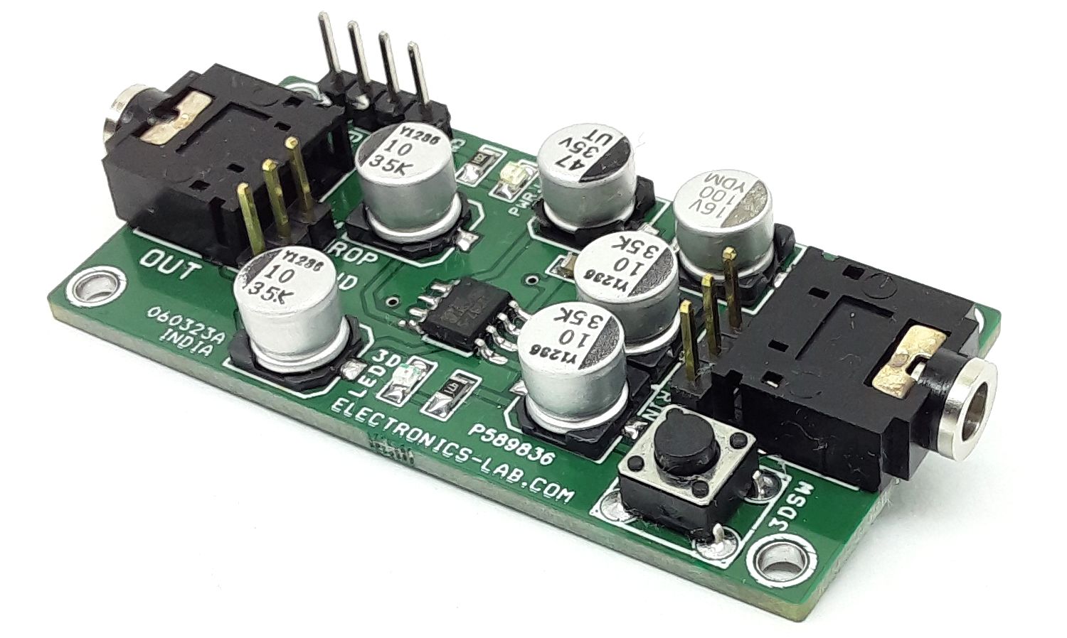
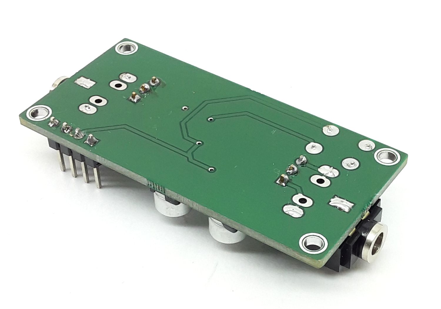
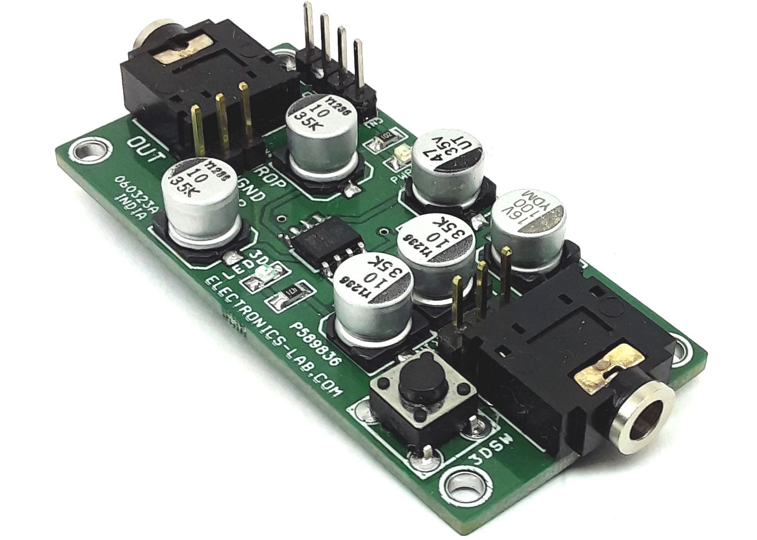
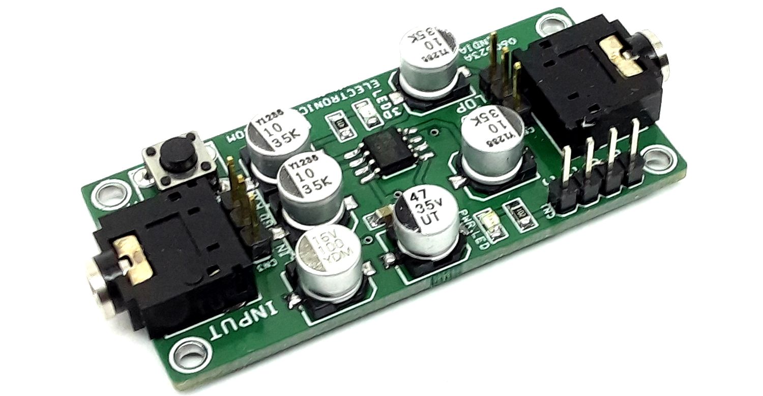
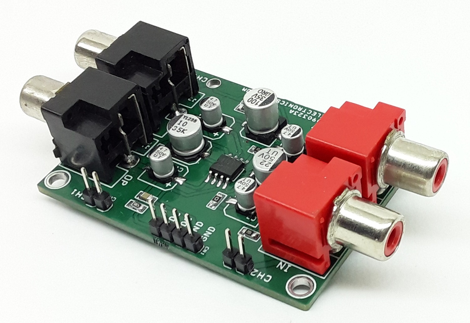
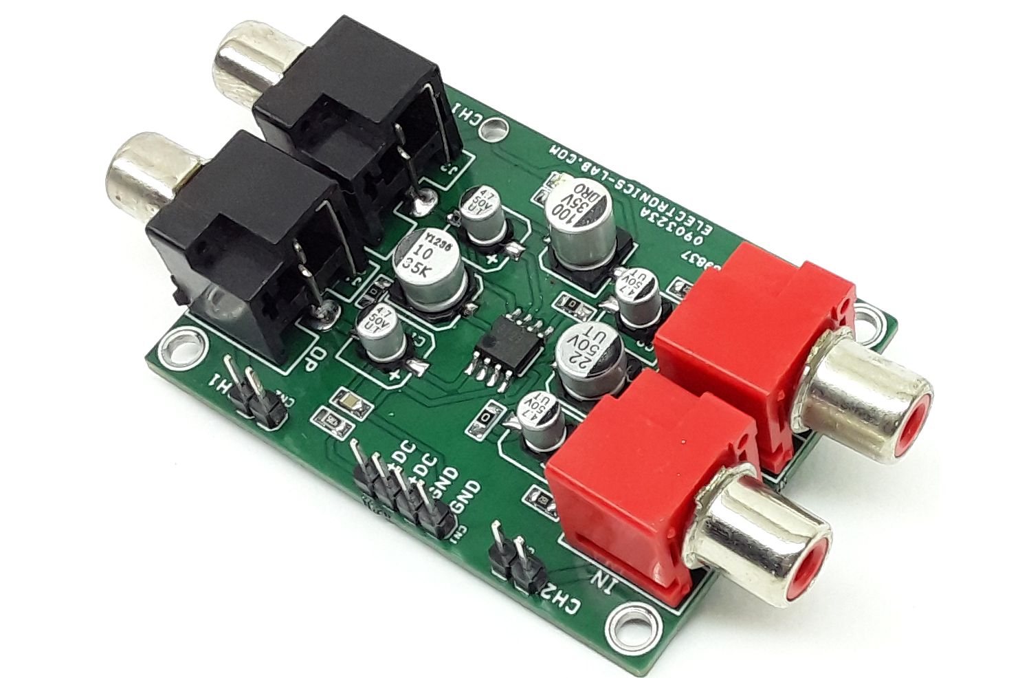
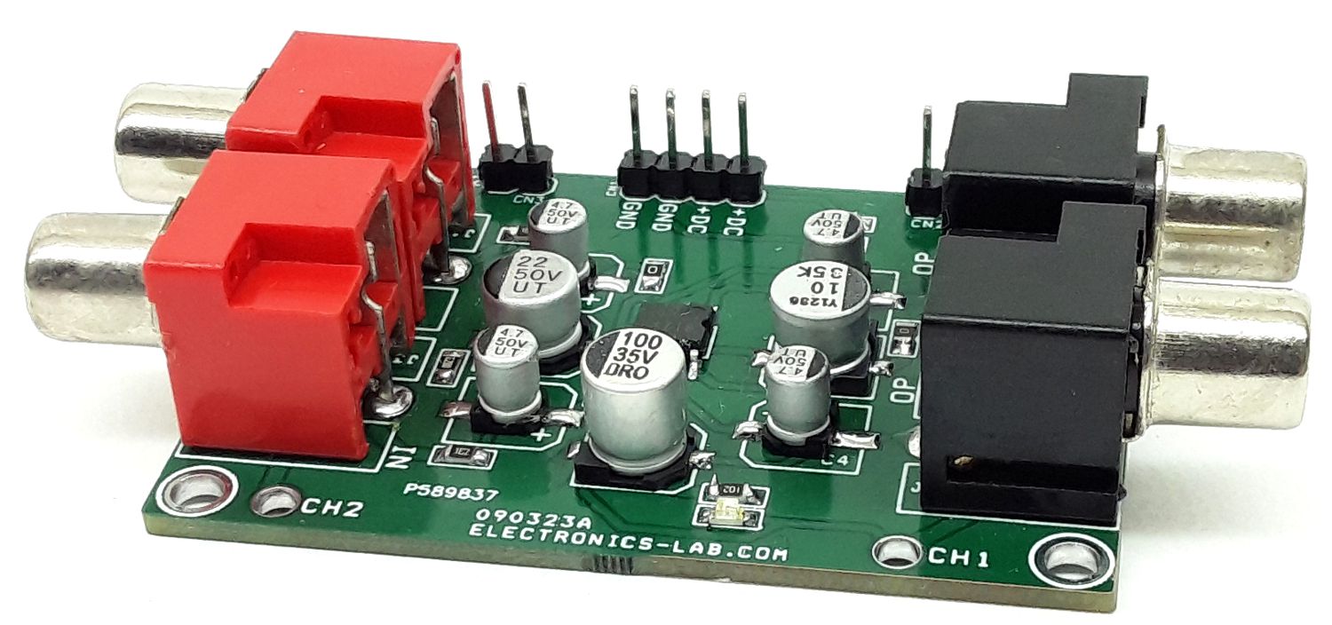
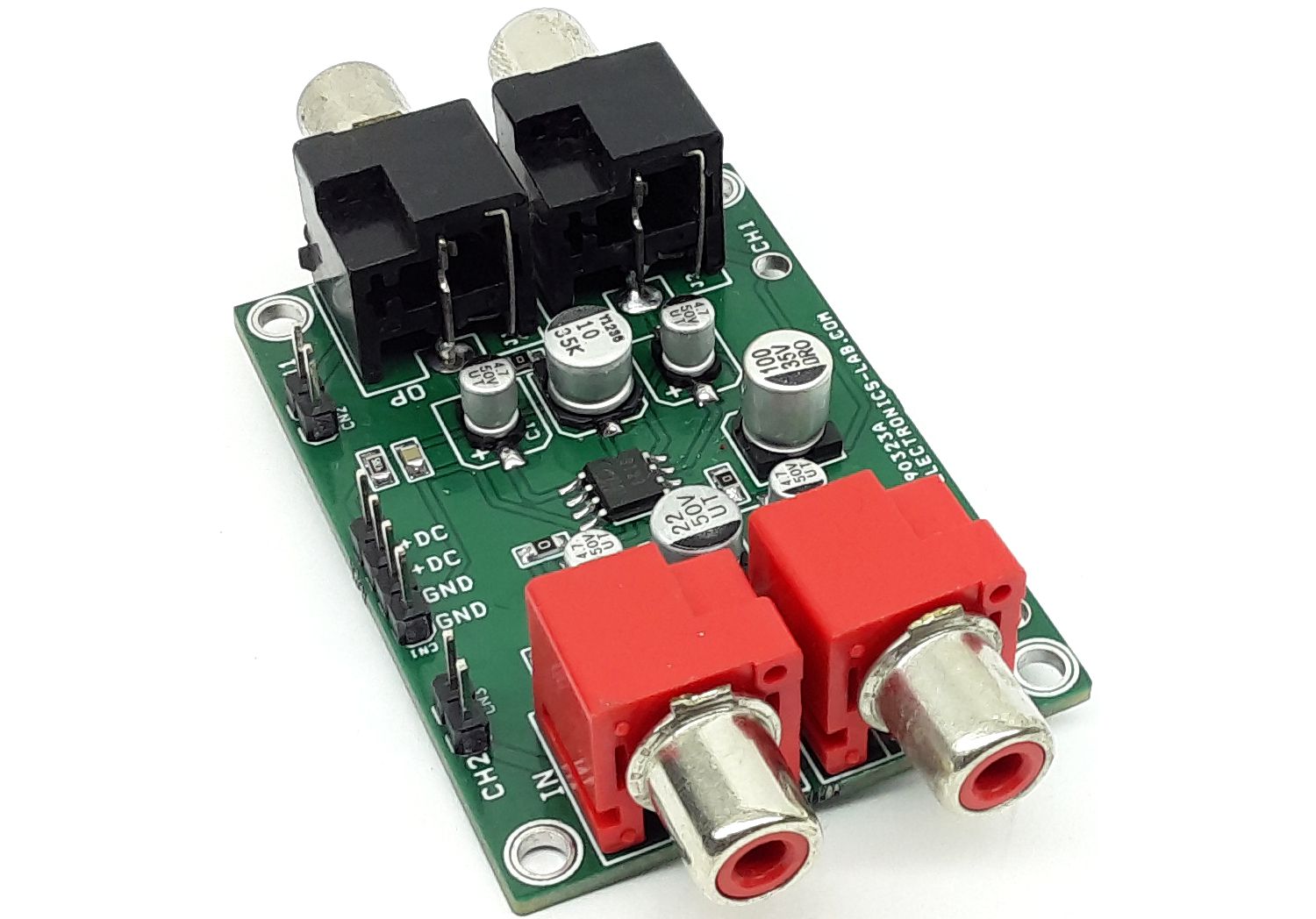
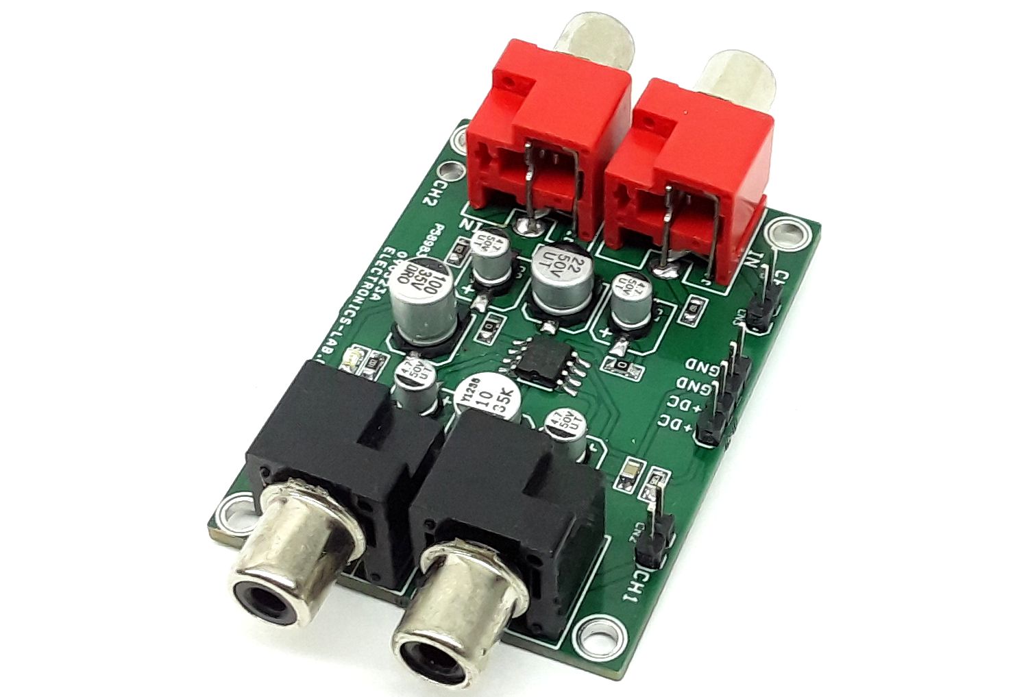
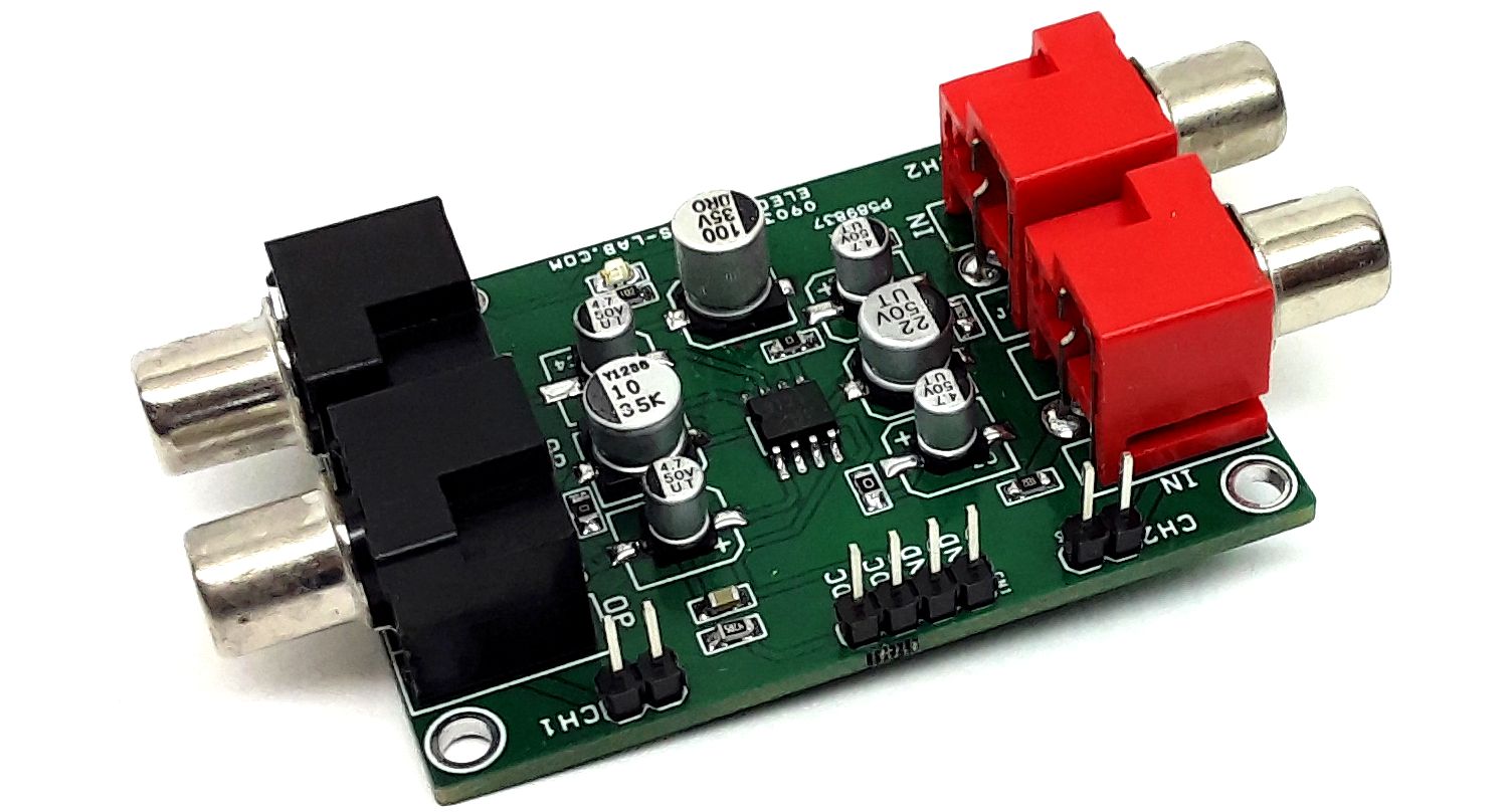
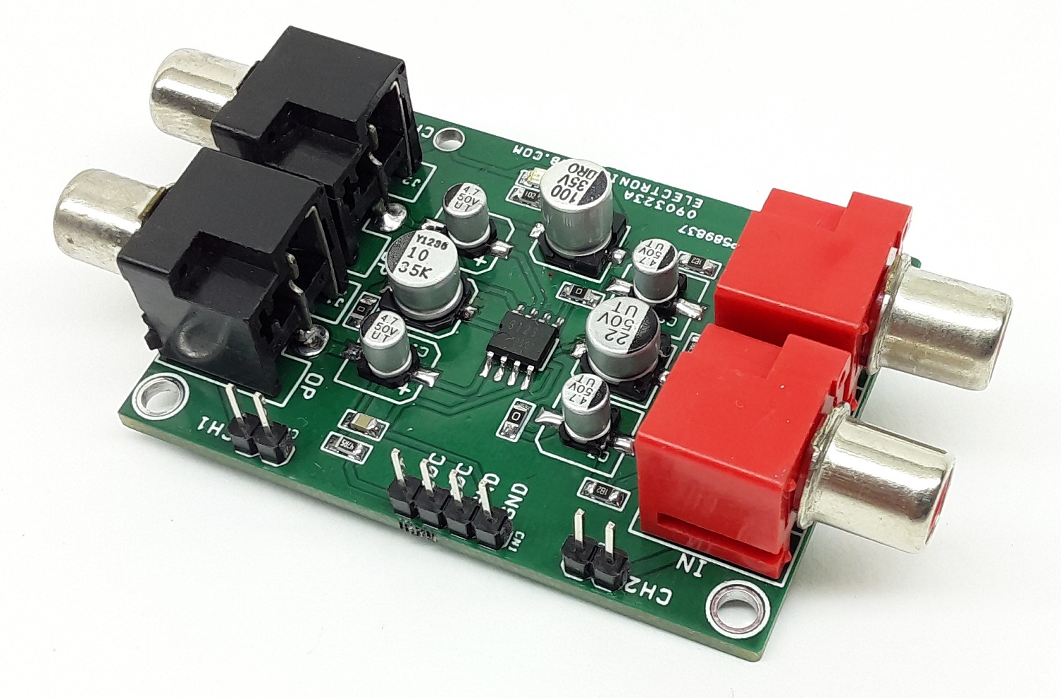
Photos