Texas Instruments bq25176M 800mA Linear Battery Charger

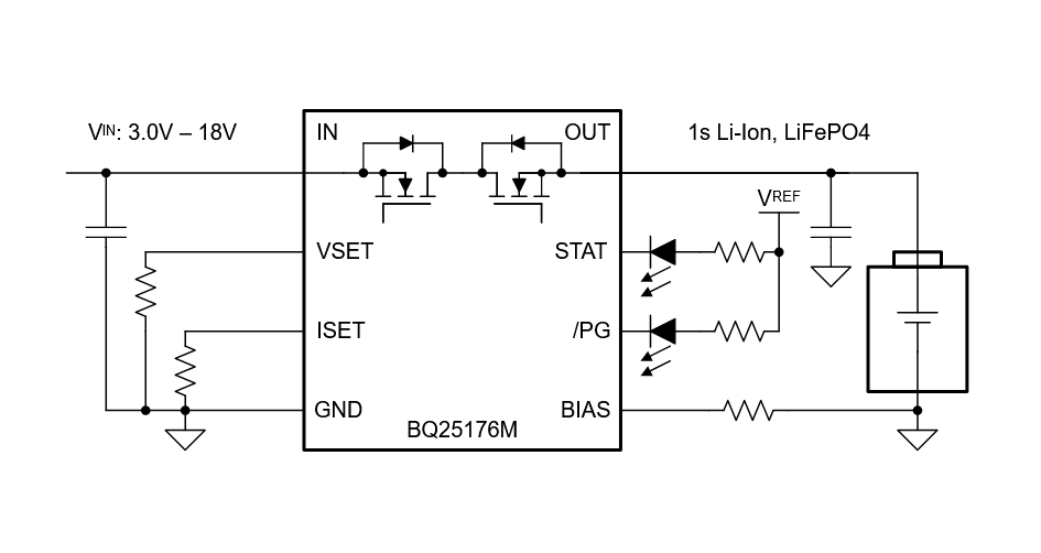
Texas Instruments bq25176M 800mA Linear Battery Charger is an integrated linear solar charger for 1-cell Li-Ion, LiFePO4, and Li-Polymer batteries with continual charge mode and battery tracking VINDPM. The device has a single power output that charges the battery. When the system load is placed in parallel with the battery, the charge current is shared between the battery and the system. The device has four phases for charging a Li-Ion/Li-Poly battery. Trickle charge is used to bring the battery voltage up to VBAT_SHORT. Precharge is used to recover a fully discharged battery. Fast-charge constant current is used to supply the bulk of the charge and voltage regulation to reach full capacity.

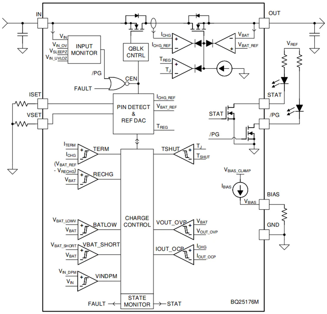
In all charge phases, an internal control loop monitors the IC junction temperature and reduces the charge current if an internal temperature threshold, TREG, is exceeded. The Texas Instruments bq25176M charge current sense and power stage functions are fully integrated. The charger function has high-accuracy current and voltage regulation loops, automatic charge termination, and a charge status display. The fast charge current and charge voltage are programmable through external resistors. The precharge and termination current threshold tracks the fast charge current setting.
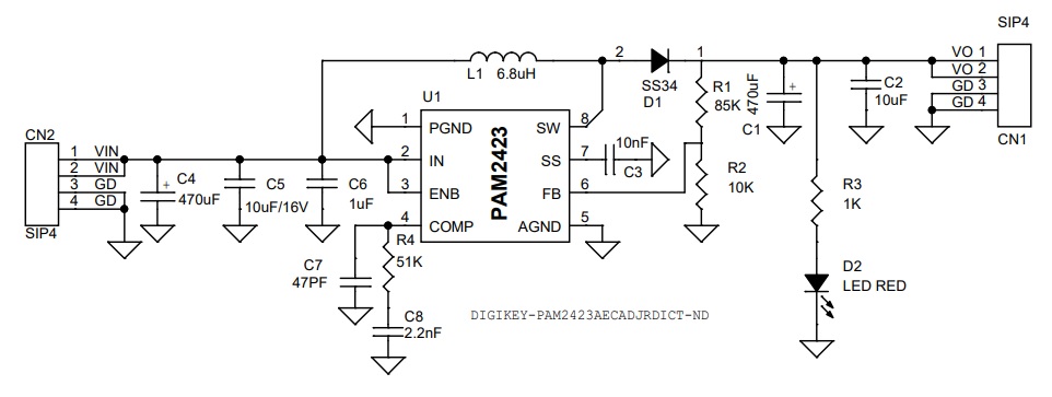
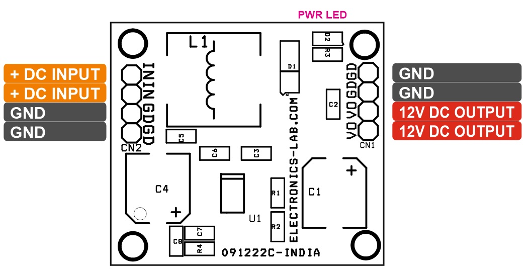
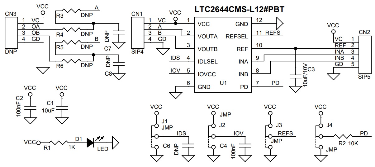
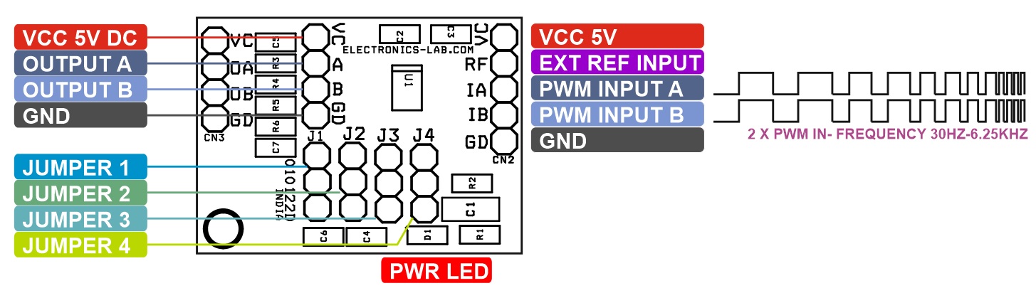
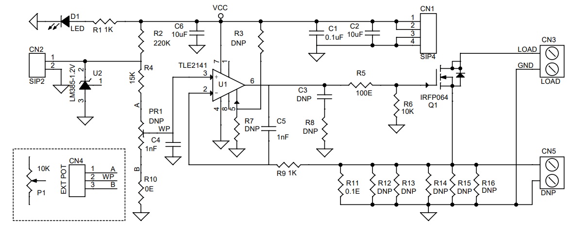
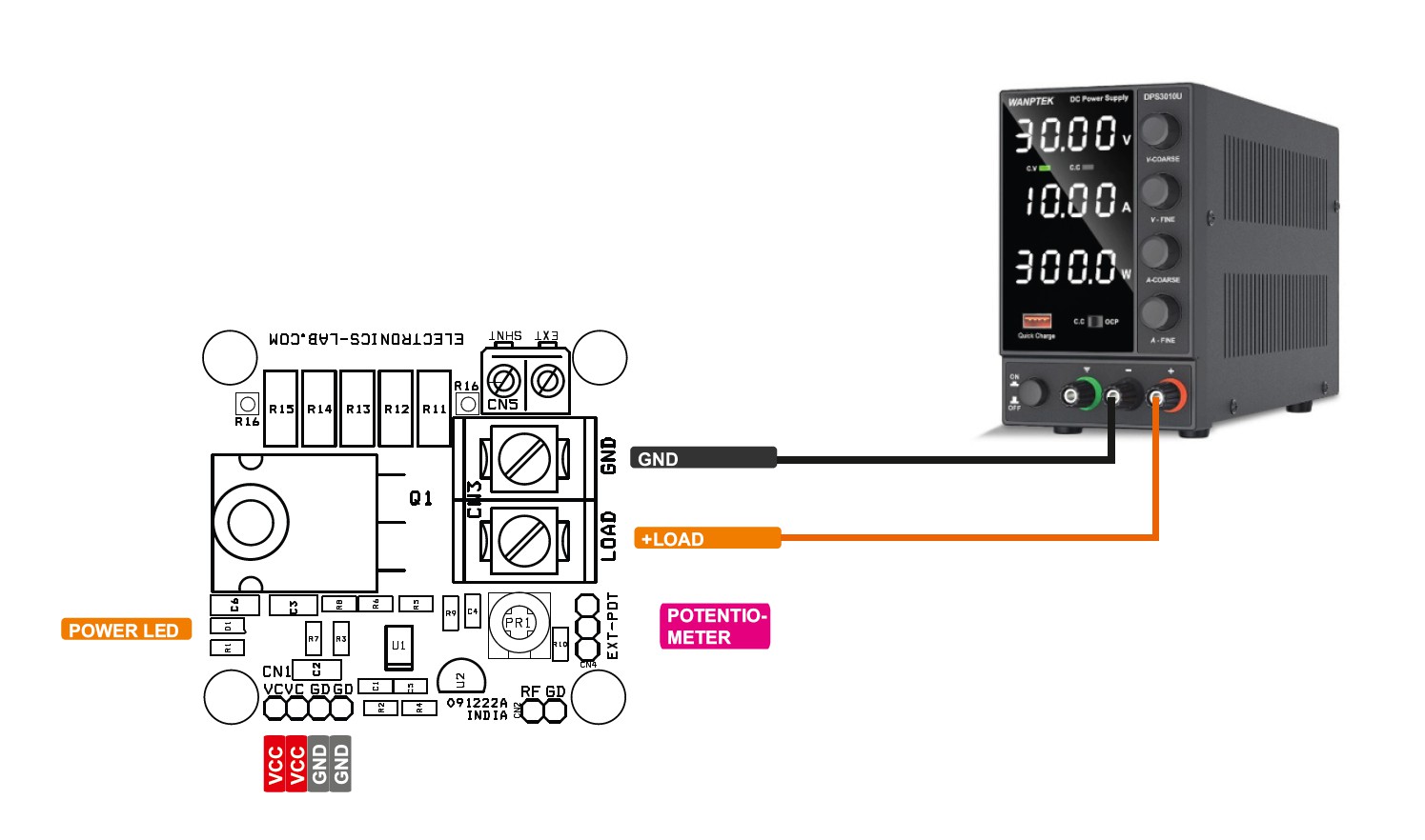
Application Diagram

Block Diagram

Features

  • Input voltage up to 30V tolerant
  • Input Voltage Based Dynamic Power Management (VINDPM) tracking battery voltage
  • Automatic sleep mode for low power consumption
    • 350nA battery leakage current
    • 80µA input leakage current when the charge is disabled
  • Supports 1-cell Li-Ion, Li-Poly, and LiFePO4
  • External resistor programmable operation
    • VSET to set battery regulation voltage
      • Li-Ion: 4.05V, 4.15V, 4.2V, 4.35V, 4.4V
      • LiFePO4: 3.5V, 3.6V, 3.7V
    • ISET to set charge current from 10mA to 800mA
  • Charging features
    • Precharge current 20% of ISET
    • Termination current 10% of ISET
    • Battery tracking input Voltage Dynamic Power Management (VINDPM) for solar charging
    • BIAS pin for charging function control
    • Open-drain output for status and fault indication
    • Open-drain output for Power Good indication
  • High accuracy
    • ±0.5% charge voltage accuracy
    • ±10% charge current accuracy
  • Integrated fault protection
    • 18.1V IN overvoltage protection
    • VSET-based OUT overvoltage protection
    • 1000mA overcurrent protection
    • 125°C thermal regulation; 150°C thermal shutdown protection
    • OUT short-circuit protection
    • VSET, ISET pins short/open protection

more information: https://www.ti.com/product/BQ25176M

The EPIC-ADS7-PUC Offers Real-Time Computing in a Compact Chassis for Robotics, Automation, and Healthcare Imaging Solutions


AAEON’s new EPIC-ADS7-PUC is the ultimate high-speed, high-powered solution compact system.

Typically associated with powerful, feature-dense 4” single-board computers, AAEON has announced the reintroduction of system-level solutions to its EPIC product line with the new EPIC-ADS7-PUC.

Powered by the 12th Generation Intel® Core processor platform with the capacity to support up to 65W CPUs, the EPIC-ADS7-PUC epitomizes the best characteristics of its SBC counterparts. With a remarkably compact 10.2″ x 6.3″ x 2.1″ (260mm x 160mm x 55mm) chassis hosting multiple high-speed interfaces alongside the ancillary features needed to make the most of its processing capacity, the system is naturally suited to markets such as robotics, IoT, and smart healthcare.

Equipped with up to 8 performance cores and 20 threads with the efficiency of hybrid processor architecture, the EPIC-ADS7-PUC’s 12th Generation Intel® Core™ contains substantial processing power. Further, the addition of 4 Gracemont efficient cores provide the device with a streamlined workload management framework for projects that require a balance of efficiency and strength.

Key Features:

  • 12th Gen Intel Core (12C/20T), supporting a 65W processor
  • High-speed interfaces (USB 3.2 Gen 2 x 6, COM x 2, and LAN x 4, HDMI 2.1 and DP 1.4a x 2)
  • Intel Time Coordinated Computing (TCC) support
  • Compact – 10.2″ x 6.3″ x 2.1″ (260mm x 160mm x 55mm)

Two DDR5 4800MHz slots offer high-speed system memory and bandwidth speed for up to six USB 3.2 Gen 2, two COM, and four LAN ports, which provide connections for peripheral devices such as cameras and sensors. The EPIC-ADS7-PUC is also home to an impressive display interface comprised of one HDMI 2.1 and two DP 1.4a ports for three simultaneous displays, which AAEON believes will make the system an excellent candidate for deployment in healthcare imaging.

Augmenting the utility of the EPIC-ADS7-PUC’s processing capacity and high-speed interfaces is its support for Intel® Time Coordinated Computing (Intel® TCC). Dramatically reducing data transmission latency, this CPU-based feature ensures the reliable execution of time-sensitive mission-critical operations such as those required in robotics applications.

With a lower height point than other system ranges, the EPIC-ADS7-PUC is easily integrated into existing projects, while its compact form factor and a plethora of interfaces compatible with real-time computing also make it the perfect solution for new projects requiring discreet deployment.

The EPIC-ADS7-PUC is now in mass production, with pricing available dependent on SKU. For more information about the EPIC-ADS7-PUC, please visit our product page or contact an AAEON representative directly.

Step Up DC-DC Converter 12V Output – 5V Input

This high-performance, fixed frequency, current-mode PWM step-up DC/DC converter efficiently produces 12V from input voltages between 3.6V to 5.5V. The project is built using the PAM2423 chip, which includes an integrated power MOSFET that supports a peak current of up to 5.5A.  The IC utilizes simple external loop compensation allowing optimization between component size, cost, and AC performance across a wide range of applications. Additional functions include an externally programmable soft-start function for easy inrush current control, internal over-voltage protection (OVP), cycle-by-cycle current limit protection, under-voltage lock-out, and thermal shutdown.

Features

  • Input Supply 5V DC (Range 3.6V to 5.5V)
  • Output 12V DC
  • Load Current Up to 500mA
  • Output Power LED
  • PCB Dimensions 35.08 X 31.12MM
  • Efficiency Up to 90%
  • Operating Frequency 520Khz
  • Soft-Start Function
  • Built-in Over-Voltage Protection (OVP)
  • Under-Voltage-Lockout
  • Under Voltage Lockout Threshold 2.5V, Hysteresis 200mV
  • Over-Current Protection – Threshold 5.5A
  • Thermal Shutdowns – Threshold 150 Degree Cent.
  • 4 X 2.5MM Mounting Holes
  • PCB Dimensions 35.08 x 31.12mm

Connections and Other Details

  • CN1: Pin 1 & 2 = V-Output 12V DC, Pin 3 & 4 = GND
  • CN2: Pin 1 & 2 = V-Input 5V DC, Pin 3 & 4 = GND
  • D2: Output LED

Schematic


Parts List

NO.QNTY.REFDESC.MANUFACTURERSUPPLIERSUPPLIER PART NO
12CN1,CN24 PIN MALE HEADER PITCH 2.54MMWURTHDIGIKEY732-5317-ND
22C1,C4470uF/16V ELECTROLYTICUNITED CHEMDIGIKEY565-4278-1-ND
31C210uF/25V CERAMIC SMD SIZE 0805YAGEO/MURATADIGIKEY
41C310nF/50V CERAMIC SMD SIZE 0805YAGEO/MURATADIGIKEY
51C510uF/16V CERAMIC SMD SIZE 0805YAGEO/MURATADIGIKEY
61C61uF/25V CERAMIC SMD SIZE 0805YAGEO/MURATADIGIKEY
71C747PF/50V CERAMIC SMD SIZE 0805YAGEO/MURATADIGIKEY
81C82.2nF/50V CERAMIC SMD SIZE 0805YAGEO/MURATADIGIKEY
91D1SS34TAIWAN SEMIDIGIKEY1801-SS34TR-ND
101D2LED RED SMD SIZE 0805OSRAMDIGIKEY475-1278-1-ND
111L16.8uH 10.4 X 10.4MMEPCOS-TDKDIGIKEY495-1808-1-ND
121R185K 1% SMD SIZE 0805YAGEO/MURATADIGIKEY
131R210K 1% SMD SIZE 0805YAGEO/MURATADIGIKEY
141R31K 5% SMD SIZE 0805YAGEO/MURATADIGIKEY
151R451K 1% SMD SIZE 0805YAGEO/MURATADIGIKEY
161U1PAM2423 SOIC8DIODE INCORPDIGIKEYPAM2423AECADJRDICT-ND

Connections

Gerber View

Photos

Video

PAM2423 Datasheet

PWM to Voltage Converter – PWM to Voltage Output DAC

The project presented here is a dual 12-bit PWM-to-voltage output DAC with high accuracy. The board is based on the LTC2644 chip. The LTC2644 measures the period and pulse width of the PWM input signals and updates the voltage output DACs after each corresponding PWM input rising edge. The DAC outputs update and settle to 12-bit accuracy within 8μs typically and are capable of sourcing and sinking up to 5mA (3V) or 10mA (5V), eliminating voltage ripple and replacing slow analog filters and buffer amplifiers. The circuit has a full-scale output of 2.5V using the 10ppm/°C internal reference. It can operate with an external reference, which sets the full-scale output equal to the external reference voltage. Each DAC enters a pin-selectable idle state when the PWM input is held unchanged for more than 60ms. The project operates from a single 2.7V to 5.5V supply and supports PWM input voltages from 1.71V to 5.5V. The PWM frequency can be any frequency between 30Hz and 6. 25kHz. The input level can be between 1.71V and 5.5V, set by a separate IOVCC pin. This project solves many problems associated with filtering a PWM signal to produce an analog voltage, producing a fast-settling, accurate analog voltage in response to a digital PWM input.

Features

  • Supply 5V (Range 2.7V to 5.5V)
  • Current Consumption approx. 15mA
  • Input PWM Signal Level Can be Between 1.71V and 5.5V
  • 2 Channel Input and Output
  • Input PWM Frequency 30Hz to 6.25Khz
  • Output 0 to 2.5V (0 to 99% Duty Cycle)
  • On Board Power LED
  • Header Connector for Inputs and Outputs
  • Jumper For Power Down
  • Jumper for Internal Reference or External Reference
  • Jumper for Idle Mode
  • Jumper for IOVC
  • PCB Dimensions 31.43 x 22.86 mm

Standalone Operation

For standalone operation. Connect a 2.7V to 5.5V supply to the VCC and a GND of CN1 Pin 1 and Pin 4. Connect the IOVCC(IOV) to VCC using Jumper J2 such that the input logic level matches the VCC supply. If a different logic level is required, remove the IOVCC(IOV) jumper and connect the middle pin2 of J2 to a supply equal to the PWM signals’ logic level to the IOVCC(IOV) and GND. There is no sequencing requirement between VCC and IOVCC. Any convenient PWM source can be used to convert the PWM signal into a voltage output.

Jumpers Settings

  • Jumper J1 (Idle Mode Select Input): Connecting this jumper to VCC or GND determines the DAC behavior when the PWM input remains high or low for more than the Idle Mode Timeout time (50ms minimum, 70ms maximum). When set to VCC (High), a low level on a PWM input will set the DAC output to a high impedance state. A high level will cause the DAC output to hold its last value. When set to GND (Low), a low level on a PWM input will set the DAC output to zero-scale, and a high level will set the DAC output to full scale.
  • Jumper J2: For normal operation Connect the IOVCC(IOV) to VCC using Jumper J2 such that the input logic level matches the VCC supply. If a different logic level is required, remove the IOVCC(IOV) jumper and connect the middle pin2 of J2 to a supply equal to the PWM signals’ logic level to the IOVCC(IOV) and GND.
  • Jumper J3: Set to GND (default) to use the internal reference. Set to EXT to supply an external reference to the REF CN2 Pin 2.
  • Jumper 4: Connect it to VCC for normal Operation, GND Power-Down.

REF: Reference Output/Input. When the REFSEL jumper is set to INT, the LTC2645’s internal reference can be measured at this point. Nominal impedance is 500Ω. If it is used to drive external circuits it must be buffered appropriately. When REFSEL is set to EXT using Jumper J3, an external reference between 1V and VCC may be connected to this point

LTC2644-L12: Supports Frequency up to 6.25Khz, for higher frequency select below chips.  

  • LTC2644-L12 Chip Supports 12Bit resolution, 30Hz to 6.25Khz input
  • LTC2644-L10 Chip Supports 10Bit resolution, 30Hz to 25Khz input
  • LTC2644-L8 Chip Supports 8 Bit resolution, 30Hz to 100Khz input

Connections and other details

  • CN1: Pin 1 = VCC 5V DC, Pin 2 = Vout Channel A, Pin 3 = Vout Channel B , Pin 4 = GND
  • CN2: Pin 1 = VCC 5V DC, Pin 2 = External Reference Optional, Pin 3 = PWM Input Channel A, Pin 4 = PWM Input Channel B
  • Jumper 1 = IDLE Setting High/Low
  • Jumper 2 = VCC for Standalone Operations Internal VCC
  • Jumper 3 = Internal Reference or External Reference Selection, Connect it GND for Normal Operation
  • Jumper 4 = Power Down, Connect it to VCC for Normal Operation, GND = Power Dow
  • D1 Power LED
  • CN3, R3, R4, R5, R6, C7, C8: Optional, can be used for output filter for smooth Output

Schematic

Parts List

NO.QNTY.DESC.REF.MANUFACTURERSUPPLIERSUPPLIER PART NO
11CN14 PIN MALE HEADER PITCH 2.54MMWURTHDIGIKEY732-5317-ND
21CN25 PIN MALE HEADER PITCH 2.54MMWURTHDIGIKEY732-5318-ND
38R3,CN3,R4,R5,R6,C6,C7,C8DNP
41C110uF/10V CERAMIC SMD SIZE 0805YAGEO/MUARATADIGIKEY
52C2,C4100nF/25V CERAMIC SMD SIZE 0805YAGEO/MUARATADIGIKEY
61C310uF/10V CERAMIC SMD SIZE 0805YAGEO/MUARATADIGIKEY
71D1LED RED SMD SIZE 0805OSRAMDIGIKEY475-1278-1-ND
84J1,J2,J3,J4JUMPER/3PIN MALE HEADER PITCH 2.54MMWURTHDIGIKEY732-5316-ND
91R11K 5% SMD SIZE 0805YAGEO/MUARATADIGIKEY
101R210K 5% SMD SIZE 0805YAGEO/MUARATADIGIKEY
111U1LTC2644CMS-L12#PBTANALOGDIGIKEY505-LTC2644CMS-L12#PBF-ND
123SHUNTSHUNT FOR JUMPERSULINS CONNECTDIGIKEYS9001-ND

Connections

Gerber View

Photos

Video


LTC2644 Datasheet

Dual 2A Power Amplifier Module for TEC

This Dual 2A Power Amplifier module is a low-cost operational amplifier designed for driving a wide variety of loads while operating on low-voltage supplies. The dual amplifier can drive high output loads with a current of up to 2A. This Dual 2A Power Amplifier has been designed as a TEC (thermoelectric cooler) driver but it can also be used for other applications such as valve driver, servo driver, transducer excitation, linear power booster, laser diode pump driver, and TEC driver. Please refer to the datasheet of OPA569 for more info. A complete temperature control loop can be created using this board and additional PID (proportional, integral, differential) control circuits and temperature amplifier modules such as the INA330. The module also can be controlled using analog voltage or DAC.

Features

  • Power Supply Input: 2.7V to 5.5V
  • Load Current: 2A
  • Output Swing: 150mV of Rails with IO =2A
  • Thermal Protection
  • Adjustable Current Limit
  • Two Flags: Current Limit and Temperature Warning
  • Shutdown Function
  • PCB Dimensions 54.77 x 31.91mm
  • PCB Mounting: 2.5mm x 4 Holes

Applications

  • Thermoelectric Cooler Driver
  • Laser Diode Pump Driver
  • Valve, Actuator Driver
  • Synchro, Servo Driver
  • Transducer Excitation
  • General Linear Power Booster For Op Amps
  • Paralleling Option For Higher Current Applications

The OPA569 is a low-cost, high-current, operational amplifier designed for driving a wide variety of loads while operating on low-voltage supplies. It operates from either single or dual supplies for design flexibility and has rail-to-rail swing on the input and output. Typical output swing is within 150mV of the supply rails, with output current of 2A. Output swing closer to the rails is achievable with lighter loads. The OPA569 is unity gain stable, has low dc errors, is easy to use, and free from the phase inversion problems found in some power amplifiers. High performance is maintained at voltage swings near the output rails.

The OPA569 provides an accurate user-selected current limit that is set with an external resistor, or digitally adjusted via a Digital-to-Analog Converter. The OPA569 output can be independently disabled using the Enable pin, saving power and protecting the load. The IMONITOR pin provides a 1:475 bidirectional copy of the output current. This eliminates the need for a series current shunt resistor, allowing more voltage to be applied to the load. This pin can be used for simple monitoring, or feedback control to establish constant output current. Two flags are provided: one for warning of thermal over-stress, and one for current limit condition. The Thermal Flag pin can be connected to the Enable pin to provide a thermal shutdown solution.

Connections and Other Details

  • CN1: Pin 1 = VCC, Pin 2 = Current Limit Flag 1, Pin 3 = +IN 1 Op-Amp, Pin 4 = Thermal Flag 1, Pin 5 = Enable 1, Pin 6 = GND
  • CN2: Pin 1 = VCC, Pin 2 = Current Limit Flag 2, Pin 3 = +IN 2 Op-Amp, Pin 4 = Thermal Flag 2, Pin 5 = Enable 2, Pin 6 = GND
  • CN3: Pin 1 = VCC, Pin 2 = GND
  • CN4: Pin 1 = Current Monitor 1, Pin 2 = GND
  • CN5: Pin 1 = Current Monitor 2, Pin 2 = GND
  • CN6: Pin 1 = VCC, Pin 2 = N2 -IN 2 Op-Amp, Pin 3 = N1 -IN 1 Op-Amp
  • D1: Power LED
  • U3: Pin 1 = -TEC, Pin 2 = +TEC

Schematic

Parts List

NOQNTYREFDESCMANUFACTURERSUPPLIERSUPPLIER'S PART NO
12CN1,CN26 PIN MALE HEADER PITCH 2.54MMWURTH732-5319-ND
21CN32 PIN SCREW TERMINAL PITCH 5.08MMPHOENIX277-1247-ND
32CN4,CN52 PIN MALE HEADER PITCH 2.54MMWURTH732-5315-ND
41CN64 PIN MALE HEADER PITCH 2.54MMWURTH732-5317-ND
51C1470uF/25V ELECTROLYTIC SMDPANASONICPCE4605CT-ND
62C2,C30.1uF/50V CERAMIC SMD SIZE 0805YAGEO/MURATA
71D1LED RED SMD SIZE 0805OSRAM475-1278-1-ND
81R1470E 1% SMD SIZE 0805YAGEO/MURATA
98R2,R4,R5,R6,R10,R11,R13,R1410K 1% SMD SIZE 0805YAGEO/MURATA
101R30E SMD SIZE 0805YAGEO/MURATA
112R7,R85.76K 1% SMD SIZE 0805YAGEO/MURATA
122R9,R12DNP
132U1,U2OPA569 SOICTI296-14174-5-ND
141U32 PIN SCREW TERMINAL PITCH 5.08MMPHOENIX277-1247-ND

Application Diagram

Connections

Gerber View

Photos

OPA569 Datasheet

Electronic DC Load using TLE2141

The circuit shown here is a low-cost electronic DC load designed to sink current from a power source. This test equipment can be used to test power devices such as power supplies, chargers, solar panels, and batteries. The board is built using op-amp TLE2141, LM385 provides the reference voltage. Resistor R11 acts as a shunt resistor and provides load current feedback to the op-amp, potentiometer P1 is provided to adjust the load current, and D1 is the power LED. A 10-turn Potentiometer is provided for fine current adjustment. The user may use a single-turn PR1 trimmer potentiometer. The load current range is up to 2.5A, and the project can handle higher currents with large-size heat-sink and forced air using a Fan. You may use a 0 to 5A Current Meter in series to measure the load current.

Note: It is advisable to use a large-size heat sink with a fan to cool the MOSFET.

Features

  • DC Power Supply 12V DC @ 20mA
  • Load Up-to 2.5A and Up-to 24V
  • On Board Power LED
  • 10 Turn Potentiometer for fine Load current Adjustment
  • Barrier Terminals for Load Connections
  • PCB Dimensions 49.53 x 46.36 mm
  • 4 x 3 mm Mounting Holes

Connections

  • CN1: Pin 1,2 = VCC 12V DC, Pin 2,3=GND
  • CN2: Pin 1 = Optional/External Ref In, PIN 2 = GND
  • CN3: Pin 1 = +Load, PIN 2 = GND
  • CN4: 10 Turn Potentiometer (Don’t Install PR1 if P1 is used)
  • PR1: Optional Single Turn Trimmer Potentiometer.
  • D1: Power LED

Schematic

Parts List

NOQNTYREF.DESC.MANUFACTURERSUPPLIERSUPPLIER PART NO
11CN14 PIN MALE HEADER PITCH 2.54MMWURTHDIGIKEY732-5317-ND
21CN22 PIN MALE HEADER PITCH 2.54MMWURTHDIGIKEY732-5315-ND
31CN32 PIN BARRIER BLOCK PITCH 9.53MMTE CONNECTIVITYDIGIKEYA98495-ND
41CN43 PIN MALE HEADER PITCH 2.54MMWURTHDIGIKEY732-5316-ND
511PR1,R3,C3,CN5,R7,R8,R12,R13,R14,R15,R16DNP
61C10.1uF/50V CERAMIC SMD SIZE 0805YAGEO/MURATADIGIKEY
72C2,C610uF/25V CERAMIC SMD SIZE 1206YAGEO/MURATADIGIKEY
82C4,C51nF/50V CERAMIC SMD SIZE 0805YAGEO/MURATADIGIKEY
91D1LED RED SMD SIZE 0805OSRAMDIGIKEY475-1278-1-ND
101R610K 5% SMD SIZE 0805YAGEO/MURATADIGIKEY
111Q1IRFP064PBF OR IRPF250VISHAYDIGIKEYIRFP064PBF-ND
122R1,R91K 5% SMD SIZE 0805YAGEO/MURATADIGIKEY
131R2220K 1% SMD SIZE 0805YAGEO/MURATADIGIKEY
141R415K 1% SMD SIZE 0805YAGEO/MURATADIGIKEY
151R5100E 5% SMD SIZE 0805YAGEO/MURATADIGIKEY
161R100E SMD SIZE 0805YAGEO/MURATADIGIKEY
171R110.1E/2W 1% SMD SIZE 2512YAGEO/MURATADIGIKEY
181U1TLE2141 SOIC8TIDIGIKEY296-10454-5-ND
191U2LM385-1.2V TO92TIDIGIKEY296-50311-ND
201P110K TEN TURN POTBOURNS INCDIGIKEY3590P-2-103L-ND

Connections

Gerber View

Photos

Video

TLE2141 Datasheet

LattePanda Team Launches LattePanda Sigma – a Hackable Single Board Server with Mighty Power

LattePanda launched the powerful and hackable single board server, the LattePanda Sigma. With its   supercomputing power, this device opens up endless possibilities for tech enthusiasts, small businesses & enterprises. With its innovative design and unique features, the LattePanda Sigma is poised to redefine the world of single board servers and drive innovation to new heights.

The LattePanda Sigma is powered by the 13th-generation Intel Core i5-1340P Rapter Lake (12-Core, 16-Thread) processor and features Intel Iris Xe Graphics, providing optimal graphics performance. Its optimized power consumption minimizes power usage by almost 50%, making it an eco-friendly choice. With 16GB of high-speed Dual-Channel LPDDR5-6400MHz RAM, the LattePanda Sigma can handle even the most demanding tasks with ease, making it perfect for graphic design, gaming, and video editing.

Key Features

  • Ultimate Performance: The LattePanda Sigma features an Intel Core i5-1340p processor with an 12 cores and 16 threads. With a maximum turbo frequency of 4.60 GHz for a performance-core and 3.4 GHz for an efficient-core, this advanced processor delivers exceptional performance and productivity for demanding tasks and multitasking.
  • Lightning-fast Memory: The dual-channel LPDDR5-6400 RAM with a capacity of 16GB ensures smooth and fast performance.
  • High-level Graphics Capability: The LattePanda Sigma adopts the advanced Intel® Iris® Xe Graphics technology which provides users with multiple display outputs, allowing for enhanced multitasking capabilities and flexible display configurations. With support for high resolutions and refresh rates, the LattePanda Sigma delivers a highly immersive and smooth visual experience.
  • Quad 4K Displays: Offering a superior viewing experience for work and play, allowing multiple applications to be displayed on the screen simultaneously. The high resolution of Quad 4K Displays provides highly immersive and realistic visual effects for gaming and entertainment, creating an exceptional viewing experience.
  • Effective Cooling: The LattePanda Sigma’s heating pipe design facilitates faster heat conduction and efficient heat dissipation, maintaining high performance and stable operation.
  • User-friendly Interface Layout: The LattePanda Sigma boasts a user-friendly and reasonable interface design that enables plug-and-play with ease.
  • Rich Interfaces: Unlocking limitless possibilities with rich interfaces, offering seamless connectivity and enhanced user experience. Dual Thunderbolt™ 4 ports provide lightning-fast data transfer speeds and versatile connectivity. Dual 2.5Gb Ethernet Ports allow for higher throughput and lower latency between devices, achieving better overall network performance.
  • Diverse OS Support: Supports Windows and Linux

Specifications

  • Processor: Intel® Core™ i5-1340P
  • CPU: 12-Core,16-Thread,12M Cache, up to 4.60 GHz (Performance-Core), 3.40 GHz (Efficient-Core)
  • Graphics: Intel® Iris® Xe Graphics, 80 Execution Units, up to 1.45 GHZ
  • Memory: 16 GBDual-Channel LPDDR5-6400MHz
  • Storage: M.2 NVMe/SATA SSD (Separately installed)
  • Network: 2x 2.5GbE RJ45 Ports (Intel@ i225-V), M2 Wireless Module (Separately Installed)
  • USB Ports: 2x USB2.0 Type-A(480Mbps), 2x USB3.2 Gen2 Tpe-A(10Gbps), 2x Thunderbolt™ 4 Type-C(40Gbps)
  • Display: HDMI2.1, up to 4096 x2304 @ 60Hz; DP 1.4a via USB Type-C, up to 7680 x 4320 @ 60Hz; eDP1.4b,up to 4096 x 2304 @120Hz
  • Co-Processor: Arduino Leonardo
  • Expansion Slots: M.2 M Key: PCle 3.0×4; M.2 M Key: PCle 4.0×4; M.2 B Key: SATA/PCle 3.0 x 1,USB2.0,USB3.0,SIM; M.2 E Key: PCle 3.0 x 1,USB2.0,Intel CNVio; Micro SIM Card Slot
  • Audio: 3.5mm Microphone Headphone Combo Connector
  • Operating System: Windows 10, Windows 11 and Ubuntu 22.04
  • Dimension: 146mm x 102mm

“We are thrilled to launch such a fantastic single board server, the LattePanda Sigma. Our team has worked tirelessly over the past months to perfect every detail of this innovative product, leaving no stone unturned in our quest for excellence. Despite the challenges and setbacks we faced along the way, our team has truly excelled in creating a powerful, energy-efficient, and compact computing solution that caters to the growing market demand. With a target audience spanning developers, IoT enthusiasts, individual users, small businesses and enterprises, our versatile and mighty power server is the perfect solution for a range of applications, including game & media servers, edge computing, home automation, AI inference and etc,”

said Youyou Yu, Product Manager of LattePanda Sigma.

To view LattePanda Sigma‘s more improved functions, please go to LattePanda – x86 Windows/Linux Single Board Computers.

Adjustable Load powered by LT3080 Regulator

Technoblogy has posted details about an adjustable load that provides a constant-current load for testing power supplies and batteries. It enables you to set the load current to up to 1.05A, using a potentiometer, and displays the current on a three-digit LED display controlled by an ATtiny84. The adjustable load can be used for more than just testing power supplies; it can also be used to test rechargeable NiMH and Li-ion batteries under different load conditions. It measures the current over time and displays the battery’s capacity in mAh or Ah. This is helpful for determining which battery brand is best, or if a battery needs to be replaced.

The constant-current circuit is based on an LT3080 regulator, which uses a current reference of 10µA, rather than a voltage reference like regulators such as the LM317. This regulator will operate down to 1.5V and a few mA, and is sensed by a 1Ω resistor, which is fed to the sense input of the regulator, via a 100kΩ potentiometer and 5.1kΩ resistor. The output of the regulator is maintained at 1.05V across the 1Ω resistor, producing a constant current of 1.05A. The LT3080 is available in a few different packages, with the TO220-5 package providing a separate VCONTROL pin, and is convenient to mount on a heatsink. The current is displayed on a three-digit 7-segment display, with a 0.28″ three-digit common anode seven-segment LED display being used.

A separate 3.7V Lipo battery is used to power the ATtiny84 and display, as this allows for testing inputs down to as low as 1V, and ensures that the microcontroller and display remain powered even when the test supply drops to zero. The potentiometer is a 100kΩ linear type, with an Alps Alpine RK09K1130C94 or Bourns PTV09A-4020U-B104 being suitable. The 5.1kΩ series resistor is added to be able to adjust the current slightly above 1A. The VCONTROL voltage must be more than 1.2V to 1.35V greater than the output voltage, and is connected to the 3.7V supply used to power the ATtiny84 and display, allowing for the adjustable load to control to as low as 1V.

The PCB was designed in Eagle and ordered from PCBWay. It was designed to fit the heatsink used, which has a thermal rating of 6.8°C/W. The total current consumption of the controller is about 10mA and it is powered by a small 3.7V Lipo cell. The PCB includes space for a 2×3 pin ICSP connector to program the ATtiny84A. All the components are through-hole, so it should be easy to solder by hand. The TO-220 LT3080 is designed for vertical mounting and needs to be gently bent with a pair of flat-nose pliers to fit the PCB. The 1Ω 2W resistor is mounted slightly above the board to improve airflow around it. The PCB also provides a 2.35″ x 1.25″ area of copper which can be used as a heatsink.

For more information about the adjustable load, visit the project page.

Picovoice Koala Noise Suppression Engine supports Raspberry Pi and Nvidia Jetson Nano

Picovoice Noise Suppression Engine on Raspberry Pi

Noise suppression technology is essential for providing clear audio during communication by eliminating unwanted background noise. While several noise suppression engines are already available, Picovoice has developed its own due to several limitations in existing technology. Most notably, the current technology lacks support for three essential parameters that a reliable noise suppression engine should possess – the ability to run on the edge with minimal latency, improved speech clarity, and platform independence.

According to Picovoice, conventional digital signal processing models are small. They can run on the device with minimal latency, but may not produce the best results in terms of noise suppression. These models are limited in handling complex and diverse noise patterns. On the other hand, deep learning models can produce higher speech intelligibility, but they typically have larger model sizes and require higher power and computing resources. As a result, running such models in real-time and across multiple platforms is not feasible.

Therefore, there is a need for a noise suppression engine that can run efficiently on-device, with minimal latency, and without requiring high power or compute resources while still producing high-quality results. Koala Noise Suppression is a noise suppression engine based on deep learning technology that enables it to achieve higher speech intelligibility while maintaining efficient performance.

Picovoice Noise Suppression Engine

The Picovoice Koala Noise Suppression technology has the capability to process voice data on the device itself, ensuring privacy and security. It can also run seamlessly across various platforms, including desktops, mobile devices, web, and embedded systems. The software model is designed to be deployed easily and quickly, with an intuitive software development kit that simplifies the integration process. This means that developers can quickly and easily implement noise suppression technology into their applications without requiring extensive knowledge or expertise in machine learning or deep learning.

Koala, an on-device noise suppression engine, recognizes the importance of supporting Raspberry Pi to enable its technology to be utilized in a broader range of applications. Additionally, the noise suppression engine is also compatible with Nvidia Jetson Nano, which is extensively used in edge artificial intelligence applications like entry-level network video recorders (NVRs), home robots, and intelligent gateways that have full analytics capabilities.

By supporting these platforms, Koala expands its potential user base and enhances its versatility in various applications. It is worth noting that the ability to operate on these platforms reflects the high adaptability of Koala to different environments and requirements.

AI accelerator module from Aetina integrates four Hailo-8 edge AI processors

Aetina has introduced AI-MXM-H84A, an MXM-embedded graphics accelerator that is specifically intended for AI processing and has been launched by Impulse Embedded. The AI accelerator module from Aetina integrates four Hailo-8 edge AI processors that offer 104 TOPS performance on a single embedded MXM graphics module. The company has designed the hardware system to be used in robotics, machine vision, autonomous vehicles, and more.

The Hail0-8 edge AI processing system offers 26 TOPS AI performance that has a power consumption of 2.5W. This application-specific integrated circuit comes from an Israel-based embedded manufacturer, Hailo. The company has designed hardware with the flexibility to offer lower power consumption and high performance in a single-design architecture.

Aetina chose MXM, which is a mobile PCI express module form factor device previously designed to be used in laptops. The AI-MXM-H84A, an AI accelerator module, can operate efficiently even in harsh environments and is intended to be incorporated into other embedded systems.

The MXM 3.1 Type B module is highly efficient and has a compact form factor, which makes it convenient for developers and system integrators to incorporate it into various embedded systems. It can handle intensive AI inference workloads with low latency and without consuming excessive power like conventional discrete graphics cards.

AI-MXM-H84A AI accelerator module hardware overview

Specifications of the AI-MXM-H84A AI accelerator module:

  • Hardware system: AI-MXM-H84A AI accelerator module
  • Processor core: 4x Hailo-8 AI processors
  • AI performance: 104 TOPS
  • Form factor: MXM 3.1 Type-B
  • Display ports: No display outputs
  • Interface: PCI Express 3.0 x16
  • Max power consumption: 115W
  • Power: Bus powered
  • Cooling: Passive, no fans
  • Dimensions: 82×105 mm

Interestingly, Aetina decided to integrate Hailo-8 processors instead of the recent launch of the Hailo-15 series of advanced vision processors. In our previous coverage of Hailo-15, the processor is specifically designed to be incorporated into smart cameras. The Hailo-15 lineup raises the benchmark for computer vision and video processing using deep learning, offering exceptional AI capabilities for a range of applications in diverse industries.

Impulse Embedded has not provided any details on the pricing; however, interested developers can choose to inquire on the official website for a quote on the chosen products.

TOP PCB Companies