1.2V-25V/10A Adjustable Power Supply Using Power Op-Amp
- Rajkumar Sharma
- 36.619 Views
- easy
- Tested
- SKU: EL70823
- Quote Now
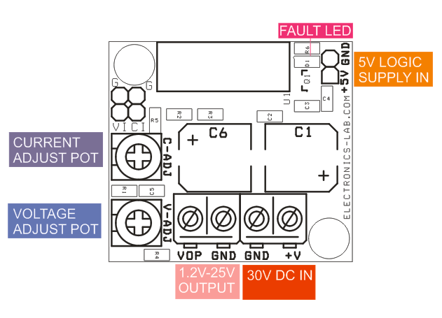
This is a small size power supply based on OPA549 power op-amp that provides output voltage 1.2V to 25V with 0 to 10A adjustable current limit. Two onboard trimmer potentiometers provided to adjust the voltage and current, LED D1 is over temperature indicator. The circuit works with input supply of 30V DC and logic supply 5V DC. IC requires large size heat sink to work with full 10A current range. Screw terminals for input and output connections are provided. The OPA549 is a low-cost, high-voltage/high-current operational amplifier ideal for driving a wide variety of loads. This laser-trimmed monolithic integrated circuit provides excellent low-level signal accuracy and high output voltage and current. The OPA549 operates from either single or dual supplies for design flexibility. The input common-mode range extends below the negative supply. The OPA549 is internally protected against over-temperature conditions and current overloads. In addition, the OPA549 provides an accurate, user-selected current limit. Unlike other designs which use a “power” resistor in series with the output current path, the OPA549 senses the load indirectly. This allows the current limit to be adjusted from 0A to 10A with a resistor/potentiometer, or controlled digitally with a voltage-out or current-out Digital-to-Analog Converter (DAC). The Enable/Status (E/S) pin provides two functions. It can be monitored to determine if the device is in thermal shutdown, and it can be forced low to disable the output stage and effectively disconnect the load. The OPA549 is available in an 11-lead power package. Its copper tab allows easy mounting to a heat sink for excellent thermal performance. Operation is specified over the extended industrial temperature range, –40°C to +85°C.
Features
- Input Supply 30V DC
- Logic Supply 5V DC
- Output 1.2V to 25V DC
- Load Current Limit Adjustable 0 To 10A
- Thermal Shutdown LED Indicator
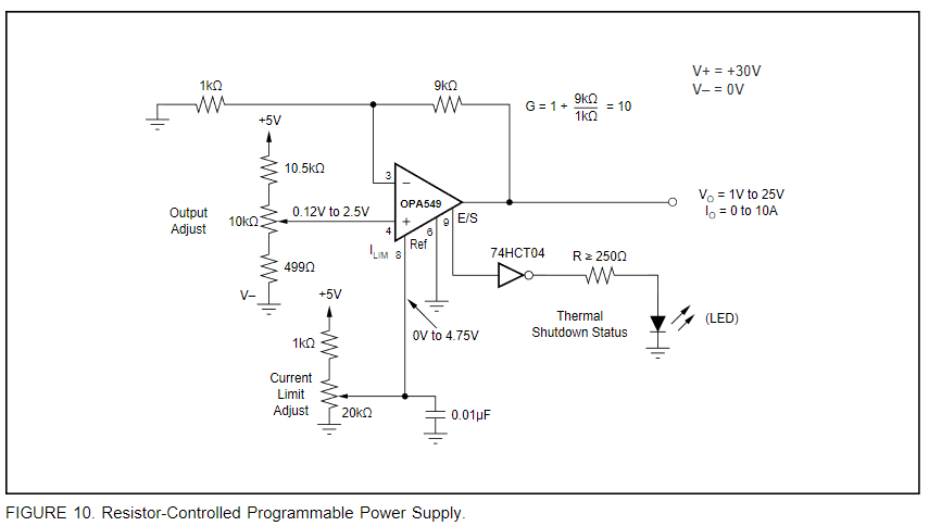
A programmable source and sink power supply can easily be built using the OPA549. Both the output voltage and output current are user controlled. See Figure 12 for a circuit using potentiometers to adjust the output voltage and current while Figure 13 uses DACs (refer to datasheet). An LED connected to the E/S pin through a logic gate indicates if the OPA549 is in thermal shutdown.
Adjustable Current limit
The OPA549’s accurate, user-defined current limit can be set from 0A to 10A by controlling the input to the ILIM pin. Unlike other designs, which use a power resistor in series with the output current path, the OPA549 senses the load indirectly. This allows the current limit to be set with a 0μA to 633μA control signal. In contrast, other designs require a limiting resistor to handle the full output current (up to 10A in this case). Although the design of the OPA549 allows output currents up to 10A, it is not recommended that the device be operated continuously at that level. The highest rated continuous current capability is 8A. Continuously running the OPA549 at output currents greater than 8A will degrade long-term reliability.
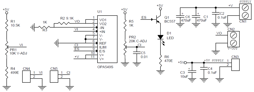
Schematic
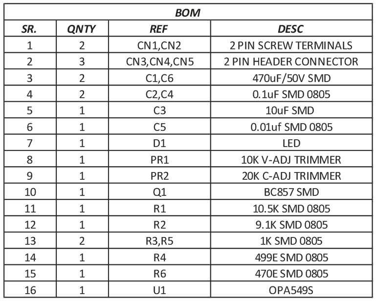
Parts List
Connections
Photos
Video




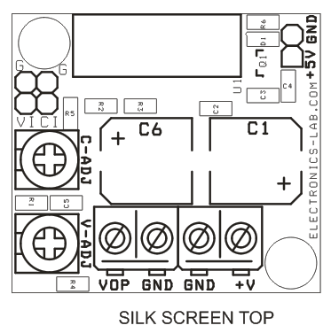
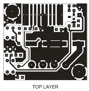
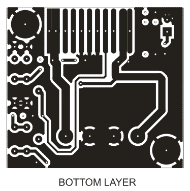


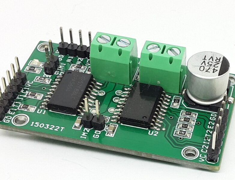
What exactly is logic supply
The 5V logic supply is needed to power the logic circuits of the OPAMP and feed the inputs, so you will be able to set the voltage and current. So, in this project, two voltages are needed, an input voltage that will be regulated by the IC and a logic voltage that needed to make the IC work.
What problem will this project actually address,like what is the background to that problem?
This project makes possible to control the voltage and current delivered from a 30V/10A source so you will be able to power your device with it. Ofcourse, you will need a 30V DC supply that will be used as the input to this circuit.
“Of course, you will need a 30V DC supply that will be used as the input to this circuit”.
Which means you could use a transformer to step down line AC to a lower secondary AC then rectify and regulate the AC to 30VDC using an electrolytic capacitor.
30V is too high for a 7805 regulator, so I presume a 15 volts zener with an adequate series resistor could be used as a source for a 7805, to get the 5 V reference.
I am looking at a design using a 24VAC secondary at 5 amps. I don’t need the full 8 amps. The OPA549 can operate from 8 VDC – 60 VDC and I am not concerned if I’m exactly at 30VDC as input. I am more concerned with getting a source for 5VDC from the same secondary without using a dedicated 5V source.
Or you could use an LM317 HV and build a regulator to bring the input V down and using the 7805 after the 317 . It will handle 57 V input. There are lots of ways to build a pre reg and using a couple of MJ2995 I think can be used to boost the current level to a more useful current. Look up some regulators using current pass Q’s with a none inductive current sharing resistor setup on each of the pass Q’s. By doing it right you can get a supply that will provide several different output Voltages at the same time which is often needed. Doing a power supply right takes a good choice of Electro caps and chokes which can improve output considerably by filtering out unwanted ripple waves.
You will need a secondary power source for the logic 5V power supply independent from the main power source, this can be a second transformer or a secondary turn on the main transformer.
I don’t see any regulation loop of any kind,please clarify.
I have attached above figure 10 from the datasheet of OPA549, where you can see the circuit in a better understandable way. You can see there is a 9k resistor going from the output to – input and that’s a negative feedback for the OPAMP which enables it to keep the output in sync with the +input and multiplied by 10. Hope this help you better understand the circuit.
Hi, how accurate is the current limit setting? And did you try to control Ulim and Ilim with the DAC?
You may replace the current set potentiometer with a precision one. We haven’t measured how accurate this is or check the set values with a DAC, this need to be tested on your end.
how can I buy this OPA 549 board?
please check your email.
Hey Mike, I see you told someone to check their Email about obtaining one of these regulator. I have a project in mind that just might make a good use for one of these myself. I could go ahead and just build the circuit on a proto board I suppose if getting one is going to be way up and out there as is sometimes. Let me know please. I have need of current limiting piece. I look at the drawings of the board and see it would be simple enough to replace the pots with larger styles which would make it more adaptable for my purposes. I need to make use of external pots so I can install the limiter board in a centralized box with other circuits for this project, and I can use some digital meters and a current sensor to monitor output and load.
Hi There. Where and how can I buy this OPA 549 board complete build?
how can I buy this OPA 549 board?
How much does this module cost?