1200V Inverter Module for 3 Phase Motors up to 2KW
- Rajkumar Sharma
- 146 Views
- advanced
- Tested
- SKU: EL154498
- Quote Now
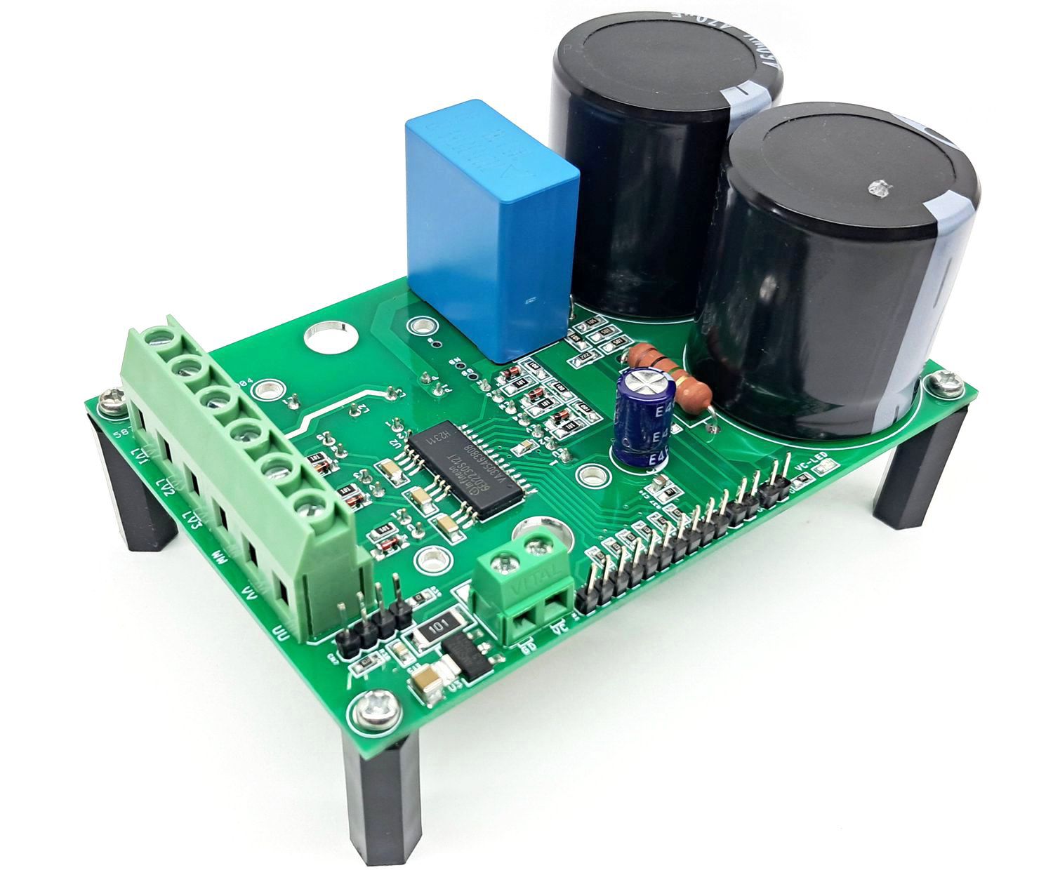
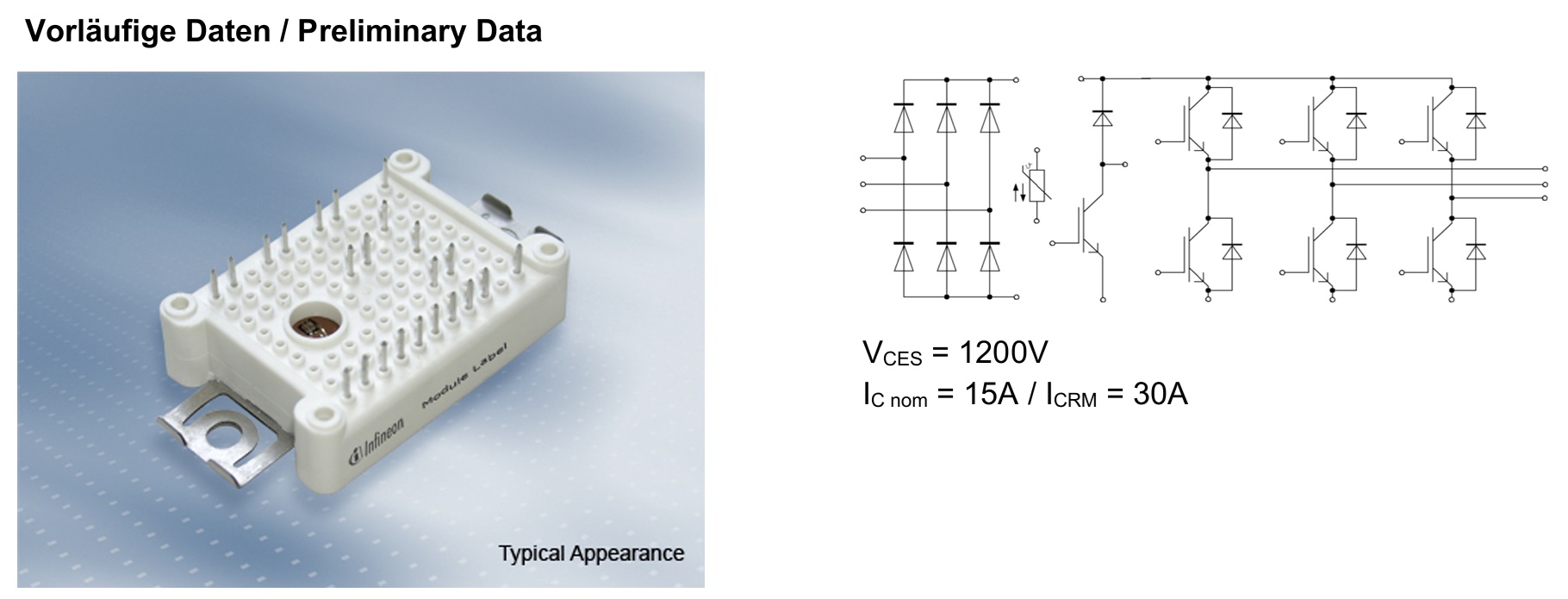
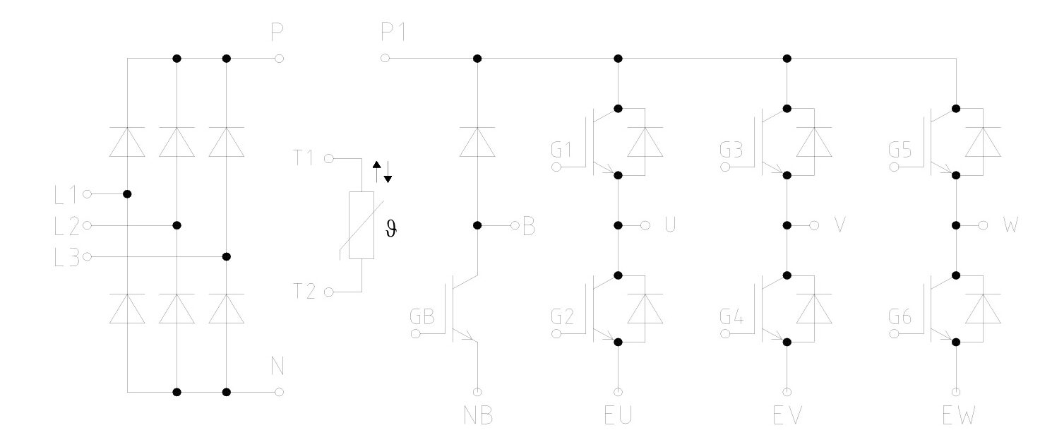
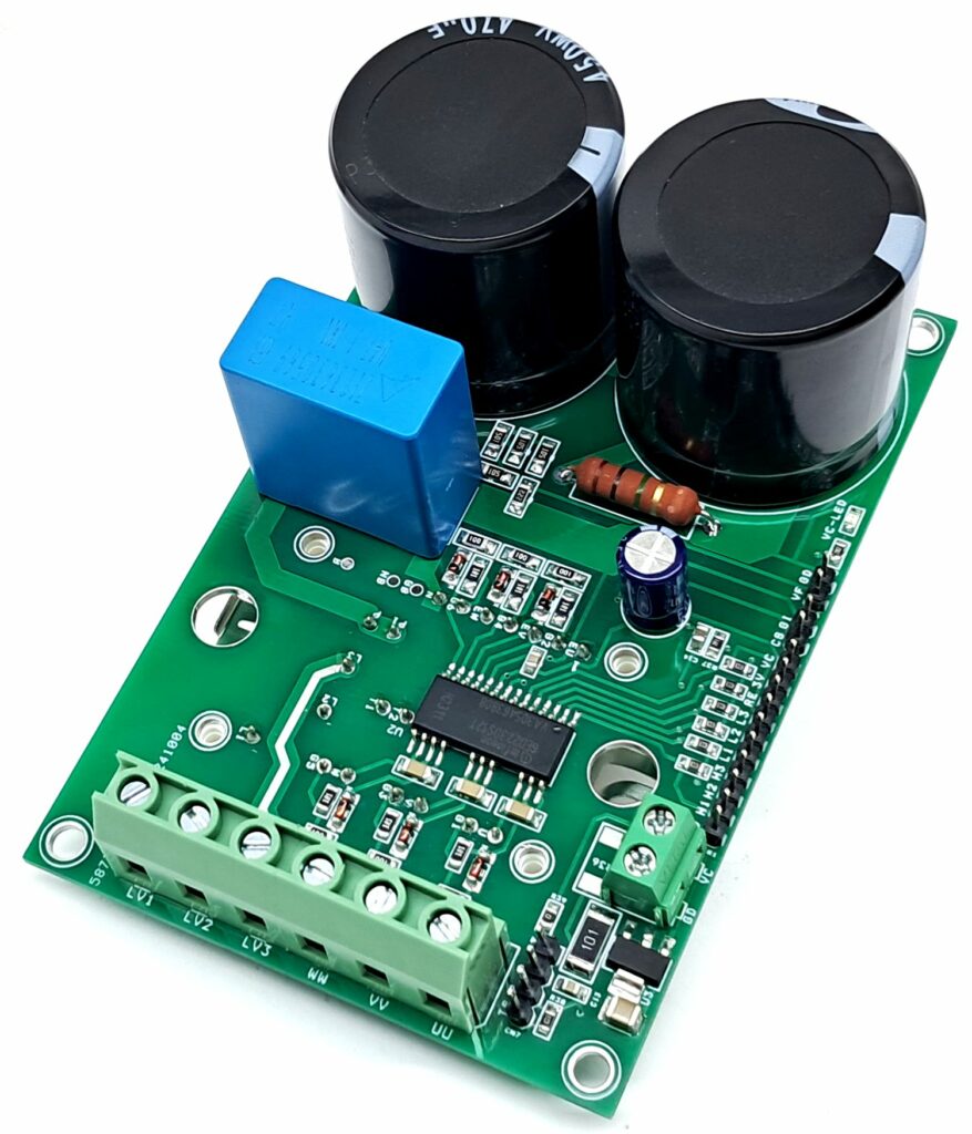
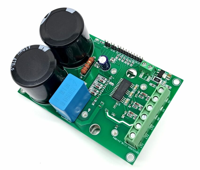
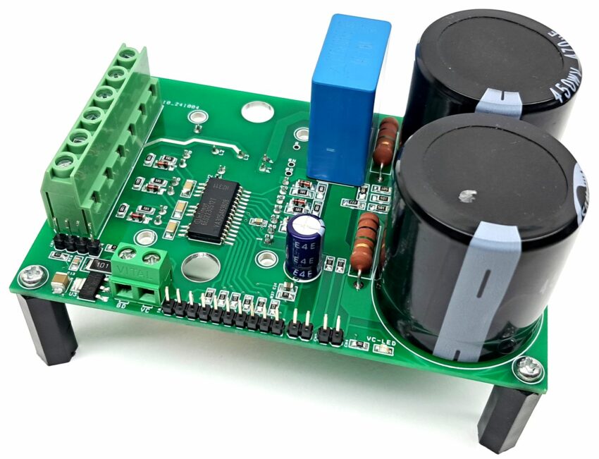
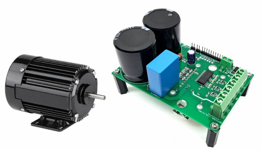
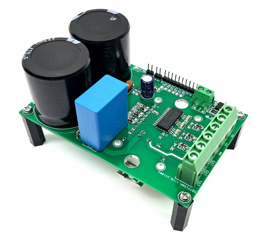
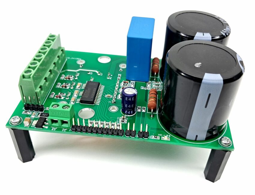
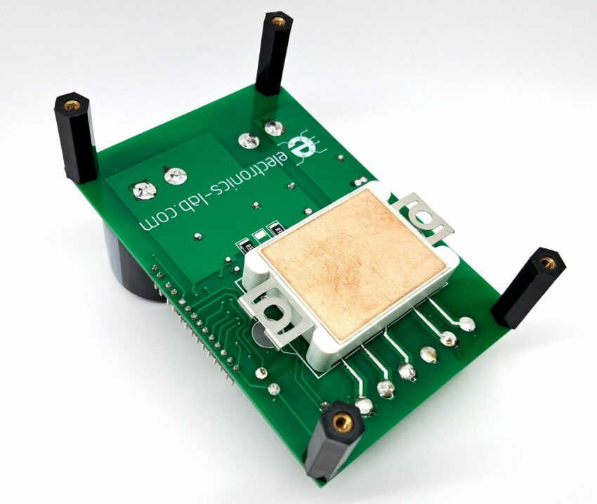
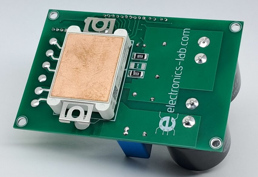
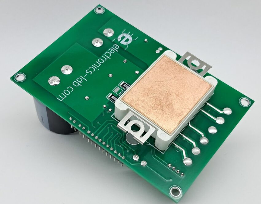
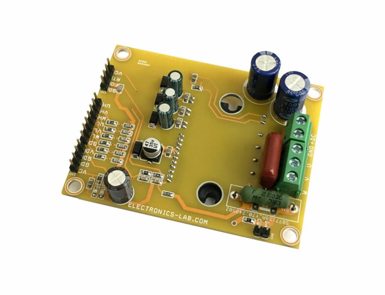
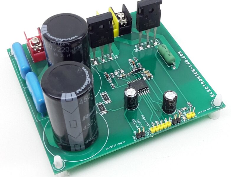
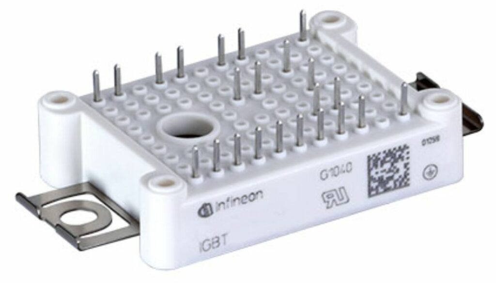
The power board described here is designed for motor applications, featuring the 6ED2230S12T gate driver IC and FP15R12W1T4 IPM power module from Infineon. It provides an AC input and a 3-phase power output, with a single emitter shunt for current sensing and a voltage divider for DC-link voltage measurement. The board includes an LM1117S33 linear regulator to generate 3.3V from the 15V VCC, which is used to supply the gate driver IC and other related circuits.
Features
- Power Input 3Phase or Single-Phase AC Input (Minimum Power Supply 200V DC and Maximum Power Supply 800V DC)
- Load 2Amp RMS (Load Up to 2KW)
- I-Trip 6AmpsPeak
- Gate Driver Power Input VCC 15V DC
- IGBT Module Temperature Feedback
- All PWM inputs have pull-down resistors
- On-Board Power LED
- Matched propagation delay for all channels
- Matched propagation delays
- 3 V, 5 V, and 15 V input logic compatible
- Undervoltage lockout protection
- Floating channel designed for bootstrap operation
- Shoot-Through protection
- Fault reporting, automatic Fault clear, and Enable function on the same pin (RFE)
- Fault reporting and programmable fault clear timer
- Over current protection with ±5% ITRIP threshold
- Truth table: Undervoltage lockout, ITRIP, and ENABLE
- Advanced input filter
- Short-Pulse / Noise rejection
- Ultra-fast, Integrated bootstrap diodes
- Negative VS transient SOA
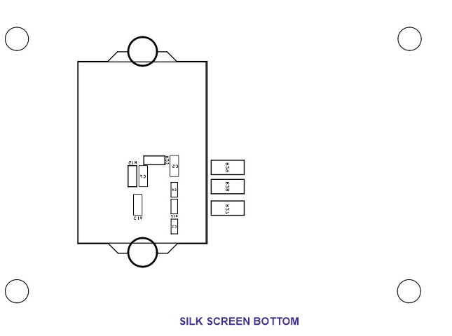
- PCB Dimensions 111.76 x 74.93 mm
- 4 x 4 mm PCB Mounting Holes
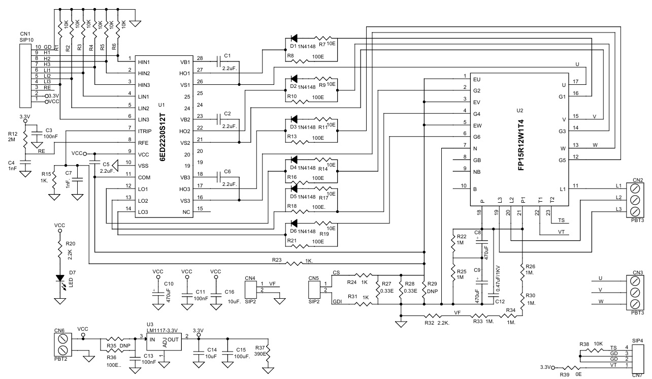
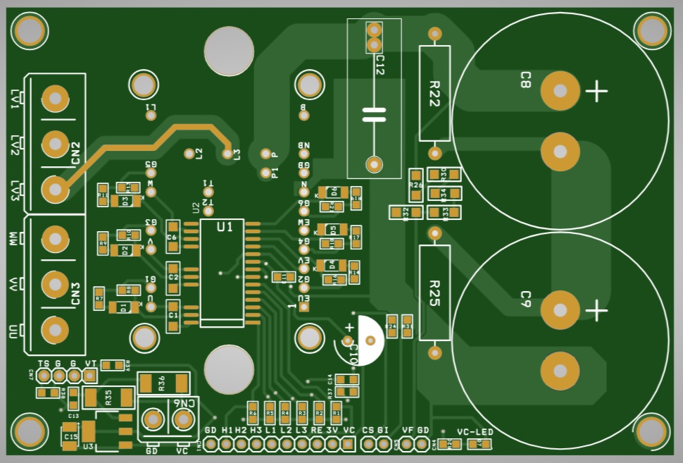
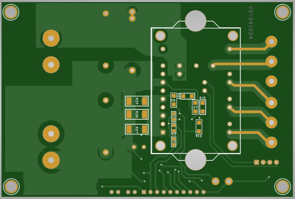
Overcurrent protection circuitry (R27+R28= Shunt Resistors and R24 and R31 provides current feedback output through CN5)
The comparator threshold can be set via the voltage divider. The ITRIP pin senses this voltage. Once an overcurrent event is detected, the driver IC outputs are shut down, and the RFE pin is pulled down to GND. The resistance value of the shunt resistors (2 x 0.33 ohm in parallel, which are used to detect the overcurrent event) is chosen to sense 6A peak current through the shunt resistors which will trigger the overcurrent protection and shut down the outputs of gate driver IC. In case a different current level is preferred (e.g., under different load conditions), the shunt resistor needs to be adjusted accordingly, taking into consideration voltage drop and power dissipation.
RFE (CN1 Pin 3)
Integrated fault reporting function like over-current (ITRIP), or low-side undervoltage lockout and the fault clear timer. This pin has negative logic and an open-drain output.
Dead-time consideration
To guarantee proper system functioning and to prevent shoot-through, a minimum of 1 us dead time is recommended from the controller side.
DC Bus Link Voltage Feedback
The project includes DC bus voltage feedback divider resistors (R26, R30, R34, R33, and R32) that provide a feedback voltage of 0.22V at 400V DC bus voltage and 0.33V at 600V DC bus voltage, accessible through pin 1 of CN1 (GND). Additionally, bleeding resistors R22 and R25 (1M/3W) are used to discharge bus capacitors C8 and C9 when power is off.
Bleeding Resistors
R22 and R25 1M/3W are bleeding resistors used to discharge bus capacitors C8 and C9 when powered off.
High Voltage Warning
Data Sheet
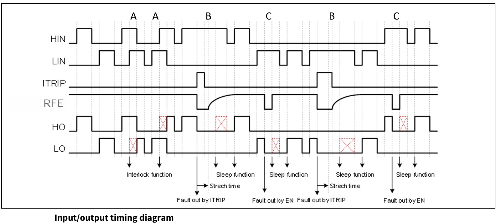
Users are also advised to refer to the datasheets of the gate driver chips and IGBT module chips before testing the board and follow the PWM input timing diagram for smooth operation.
Gate Driver Chip
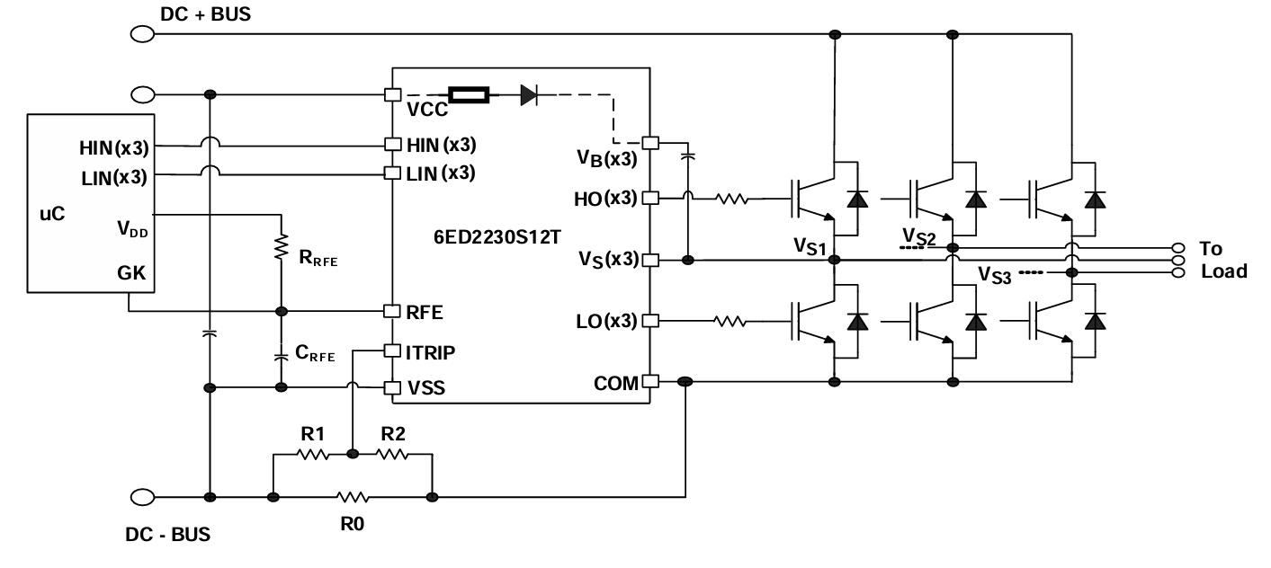
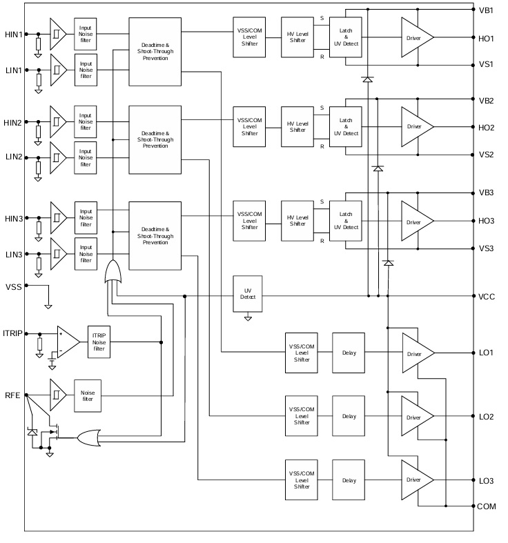
The 6ED2230S12T is a high voltage, high speed IGBT with three independent high side and low side referenced output channels for three phase applications. Proprietary HVIC and latch immune CMOS technologies enable ruggedized monolithic construction. The logic input is compatible with standard CMOS or TTL outputs, down to 3.3 V logic. An over-current protection (OCP) function which terminates all six outputs can also be derived from this resistor. An open drain FAULT signal is provided to indicate that an over-current or undervoltage shutdown has occurred. Fault conditions are cleared automatically after a delay programmed externally via an RC network. The output drivers feature a high-pulse current buffer stage designed for minimum driver cross-conduction. The floating channel can be used to drive N-channel power MOSFETs or IGBTs in the high side configuration which operates up to 1200 V. Propagation delays are matched to simplify the HVIC’s use in high frequency applications.
Connections
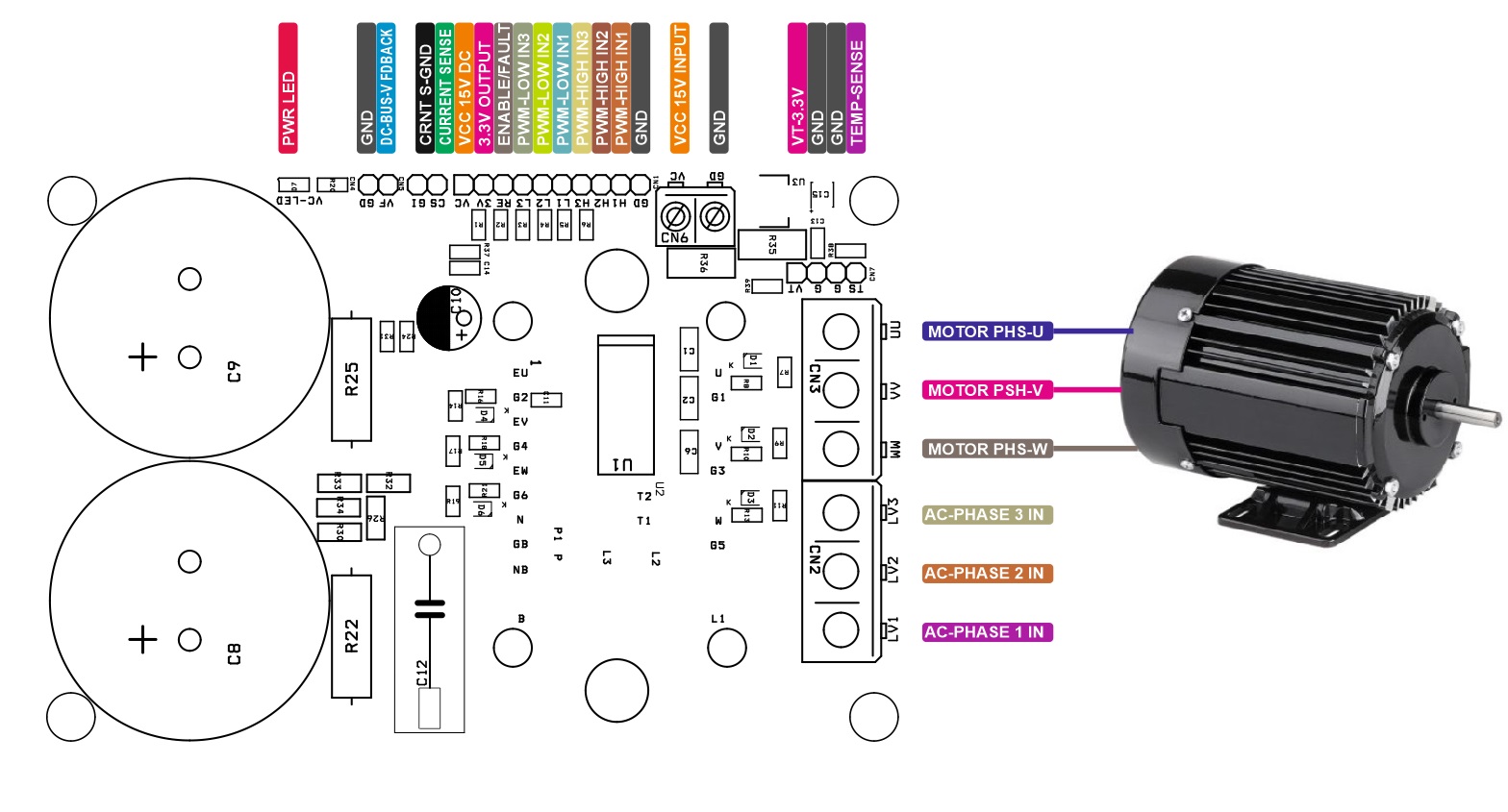
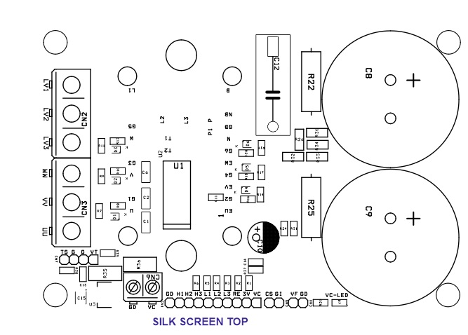
- CN1: Pin 10 = GND, Pin 9 = PWM High 1 In, Pin 8 = PWM High 2 In, Pin 7 = PWM High 3 In, Pin 6 = PWM Low 1 In, Pin 5 = PWM Low 2 In, Pin 4 = PWM Low 3 In, Pin 3 = RE Enable/Fault, Pin 2 = 3.3V Output Maximum 800mA, Pin 1 = VCC 15V DC Input
- CN2 AC Power Input: Pin 1 = L1/AC Phase Input 1, Pin 2 = L2/AC Phase 2 Input, Pin 3 = L3/AC Phase 3 Input
- CN3 Motor: Pin 1 = Phase U, Pin 2 = Phase V, Pin 3 = Phase W
- CN4 DC Bus Voltage Feedback: Pin 1 = Voltage Feedback, Pin 2 = GND
- CN5 Current Sense Output: Pin 1 = + Current Sense Output, Pin 2 = -Current Sense Output
- CN6 Gate Driver Power Input: Pin 1 VCC 15V Input, Pin 2 = GND
- CN7 Temperature Feedback: Pin 1 = Temperature Voltage Output (R38 divider resistor with Inbuilt NTC) , Pin 2 = GND, Pin 3 = GND, Pin 4 VT/3.3V Pull-Up
- D1: Power LED
Schematic
Parts List
| NO | QNTY. | REF. | DESC. | MANUFACTURER | SUPPLIER | SUPPLIER PART NO |
|---|---|---|---|---|---|---|
| 1 | 1 | CN1 | 10 PIN MALE HEADER PITCH 2.54MM | WURTH | DIGIKEY | 732-2670-ND |
| 2 | 2 | CN2,CN3 | 3 PIN SCREW TERMINAL PITCH 7.62MM | PHOENIX | DIGIKEY | 277-5954-ND |
| 3 | 2 | CN4,CN5 | 2 PIN MALE HEADER PITCH 2.54MM | WURTH | DIGIKEY | 732-5315-ND |
| 4 | 1 | CN6 | 2 PIN SCREW TERMINAL PITCH 2.54MM | PHOENIX | DIGIKEY | 277-1247-ND |
| 5 | 1 | CN7 | 4 MALE HEADER PITCH 2.54MM | WURTH | DIGIKEY | 732-5317-ND |
| 6 | 4 | C1,C2,C5,C6 | 2.2uF/35V X7R CERAMIC SMD SIZE 1206 | KYOCERA | DIGIKEY | 478-9949-1-ND |
| 7 | 3 | C3,C11,C13 | 100nF/50V CERAMIC SMD SIZE 0805 | YAGEO/MURATA | DIGIKEY | |
| 8 | 1 | C4 | 1nF/50V CERAMIC SMD SIZE 0805 | YAGEO/MURATA | DIGIKEY | |
| 9 | 1 | C7 | 1nF/50V CERAMIC SMD SIZE 1206 | YAGEO/MURATA | DIGIKEY | |
| 10 | 3 | C8,C9,C10 | 470uF/450V 35MM DIA/30MM-H ELEKTROLYTIC | RUBYCON | DIGIKEY | 1189-4275-ND |
| 11 | 1 | C12 | 0.47uF/1KV | EPCOS | DIGIKEY | 495-B32653A0474J000-ND |
| 12 | 1 | C14 | 10uF/50V CERAMIC SMD SIZE 0805 | YAGEO/MURATA | DIGIKEY | |
| 13 | 1 | C15 | 100uF/10V CERAMIC SMD SIZE 1206 OR 1210 | YAGEO/MURATA | DIGIKEY | |
| 14 | 1 | C16 | 10uF/50V CERAMIC SMD SIZE 1206 | YAGEO/MURATA | DIGIKEY | |
| 15 | 6 | D1,D2,D3,D4,D5,D6 | 1N4148 SMD | ONSEMI | DIGIKEY | LL4148FSCT-ND |
| 16 | 1 | D7 | LED RED SMD SIZE 0805 | OSRAM | DIGIKEY | 475-1278-1-ND |
| 17 | 7 | R1,R2,R3,R4,R5,R6,R38 | 10K 5% SMD SIZE 0805 | YAGEO/MURATA | DIGIKEY | |
| 18 | 6 | R7,R9,R11,R14,R17,R19 | 10E 5% SMD SIZE 0805 | YAGEO/MURATA | DIGIKEY | |
| 19 | 6 | R8,R10,R13,R16,R18, R21 | 100E 5% SMD SIZE 0805 | YAGEO/MURATA | DIGIKEY | |
| 20 | 1 | R12 | 2M 5% SMD SIZE 0805 | YAGEO/MURATA | DIGIKEY | |
| 21 | 2 | R15,R23 | 1K 5% SMD SIZE 1206 | YAGEO/MURATA | DIGIKEY | |
| 22 | 1 | R20 | 2.2K 5% SMD SIZE 0805 | YAGEO/MURATA | DIGIKEY | |
| 23 | 2 | R22,R25 | 1M/3W THT | TE CONNECTIVITY | DIGIKEY | A138410TB-ND |
| 24 | 2 | R24,R31 | 1K 5% SMD SIZE 0805 | YAGEO/MURATA | DIGIKEY | |
| 25 | 4 | R26,R30,R33,R34 | 1M 5% SMD SIZE 1206 | YAGEO/MURATA | DIGIKEY | |
| 26 | 2 | R27,R28 | 0.33E/2W 1% SMD SIZE 2512 | STACKEPOLE | DIGIKEY | CSRN2512FKR330CT-ND |
| 27 | 2 | R29,R35 | DNP | |||
| 28 | 1 | R32 | 2.2K 5% SMD SIZE 1206 | YAGEO/MURATA | DIGIKEY | |
| 29 | 1 | R36 | 100E/1W-2W 5% SMD SIZE 2512 | YAGEO/MURATA | DIGIKEY | |
| 30 | 1 | R37 | 390E 5% SMD SIZE 0805 | YAGEO/MURATA | DIGIKEY | |
| 31 | 1 | R39 | 0E 5% SMD SIZE 0805 | YAGEO/MURATA | DIGIKEY | |
| 32 | 1 | U1 | 6ED2230S12T | INFINEON | DIGIKEY | 448-6ED2230S12TXUMA1CT-ND |
| 33 | 1 | U2 | FP15R12W1T4 | INFINEON | DIGIKEY | FP15R12W1T4B3BOMA1-ND |
| 34 | 1 | U3 | LM1117-3.3V | TI | DIGIKEY | LM1117MP-3.3/NOPBCT-ND |
| 35 | 1 | C10 | 470uF/25V | WURTH | DIGIKEY | 732-8636-3-ND |
Connections
Gate Driver Example
Gate Driver Block Diagram
Input – Output Timing Diagram
IPM Diagram
IGBT Internal Diagram
Gerber View
Photos


