12W Audio Amplifier
- Rajkumar Sharma
- 36.745 Views
- moderate
- Tested
- SKU: EL34149
- Quote Now
This project is intended for use as low frequency class AB audio amplifier.
Description
Project is built around TDA2006 PENTAWATT package. TDA2006 provide high output current and has very low harmonic cross-over distortion. Further the device incorporate- rates an original (and patented) short circuit protection system comprising an arrangement for automatically limiting the dissipated power so as to keep the working point of the output transistors within their safe operating area. A conventional thermal shutdown system is also included. The TDA2006 is pin to pin equivalent to the TDA2030.
Specifications:
- 18V 2amps Single Supply
- Power supply up to 18 VDC
- Output power 12 W @ 4 Ω, 8 W @ 8 Ω
- TDA2006 provides high output current
- Has very low harmonic and cross-over distortion
- Short circuit protection/Thermal shutdown system in IC
- Terminal pins for connecting audio signal input
- Header connector for connecting potentiometer (POT) for volume adjustment
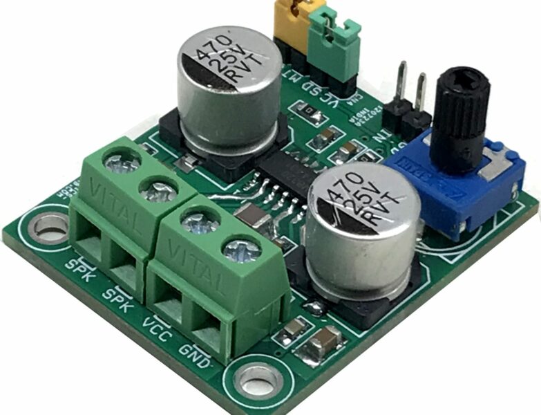
- Screw terminal connector for easy power supply input and speaker connection
- Power-On LED indicator
- Heatsink for IC
- Four mounting holes of 3.2 mm each with nut and stud
- PCB dimensions 51 mm x 63 mm
Schematic


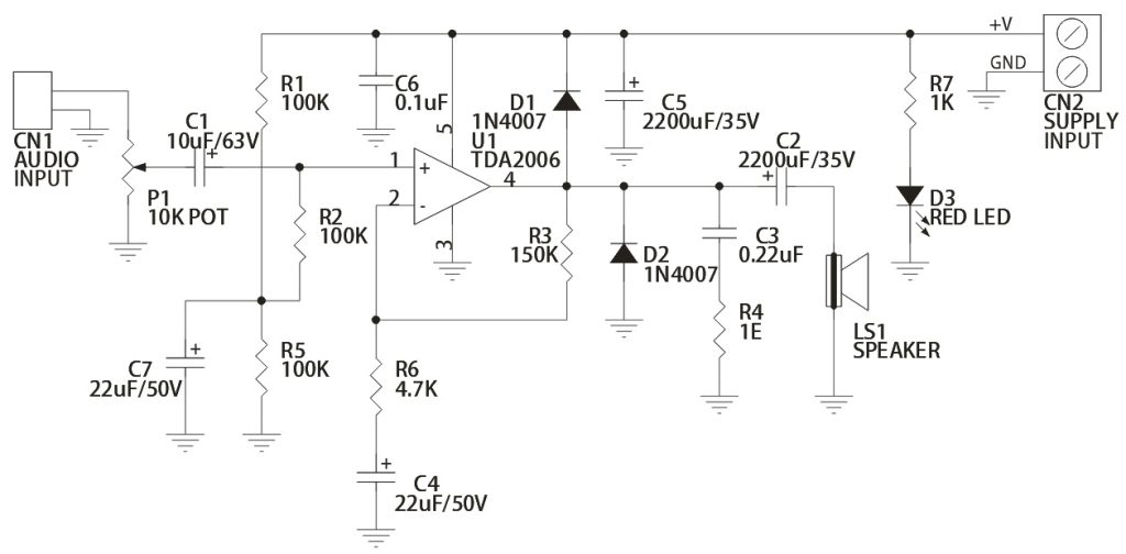
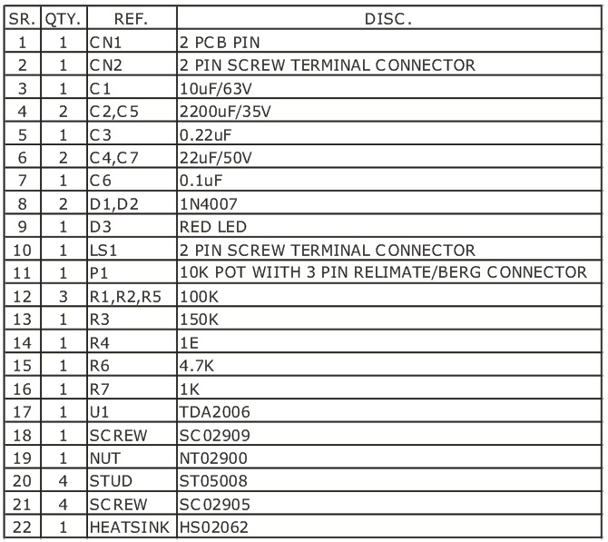
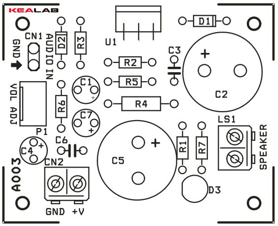
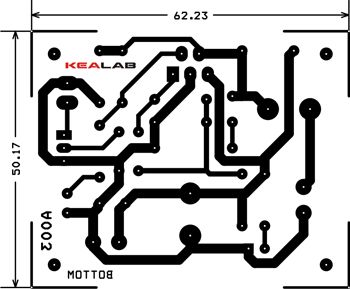


tc124578
Nice layout. I’m going to see if i can build this myself. I like how you add the pcb layout for those using pcb. I was trying to see which components go to which using your pcb layout but for some reason i having trouble to place the components to the right way lol.
Which component/s do you have problem with?
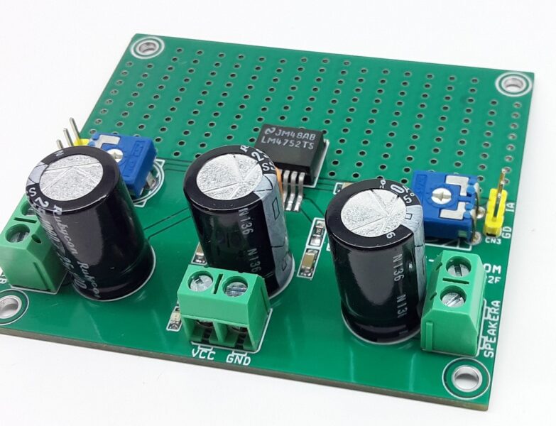
Thank you i actually end up figuring the placement of the components in the PCB layout. Actually this is something else that is bothering me is with the C2 &C5. It stated that c2 and c5 are 2200uF/35V but why in the picture i see that those are 25V/2200uF? I hope you see this message and thank in advance for the response.
C2 and C5 maximum rated voltage is 35V. That is to keep the capacitors safe in case these voltages appear across them. If you place 25V capacitors, like the photo, the amplifier will work but capacitors may die soon if higher than rated voltage is appeared on them. This can happen when the amplifier is working at it’s maximum power output. So i would suggest using 35V capacitors and ignore the photo, which is there for illustration purposes.
I want the proteus design of this project! Can u plz do it for me…