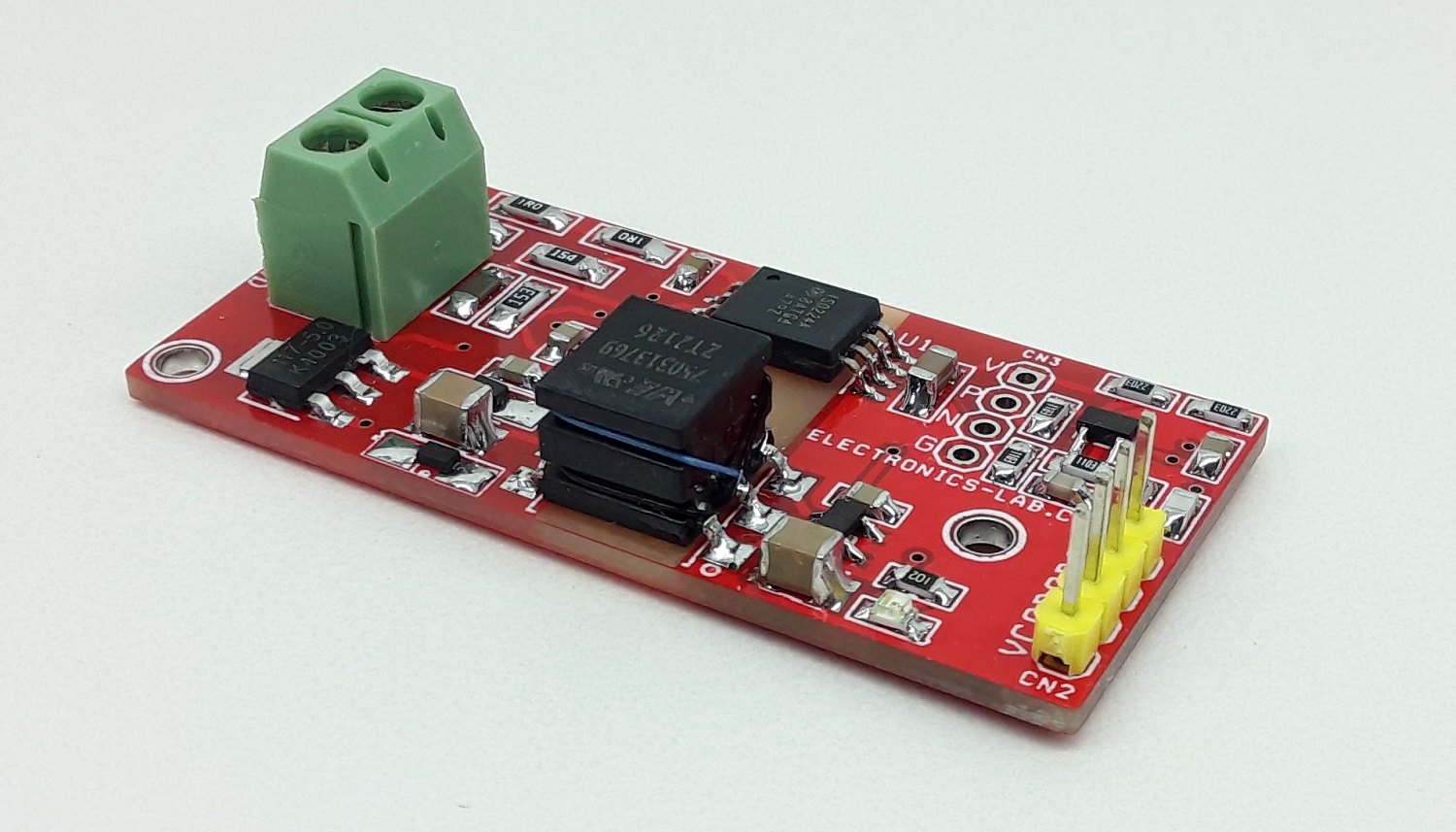
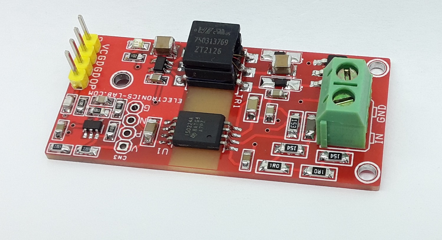
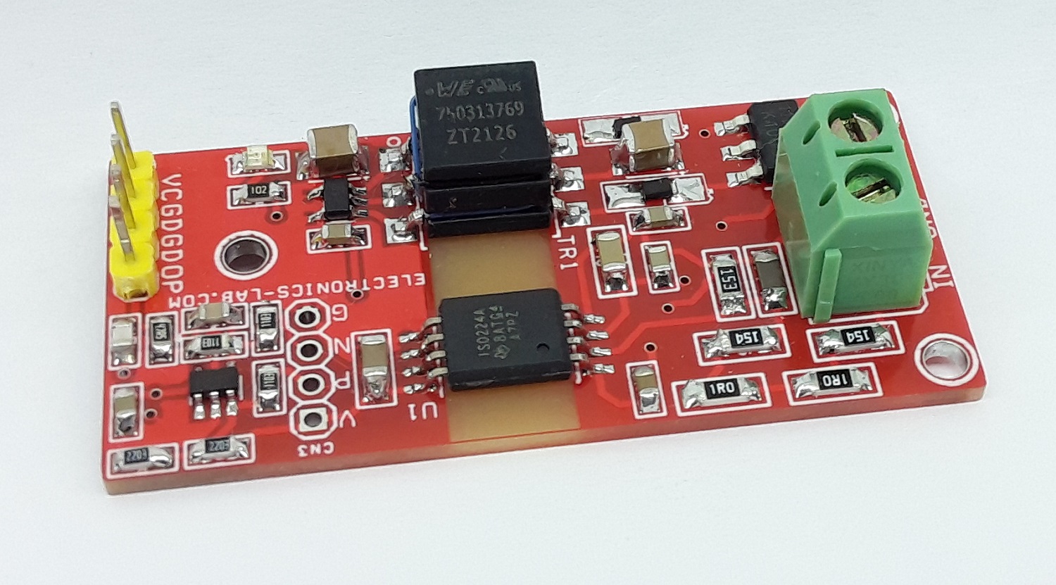
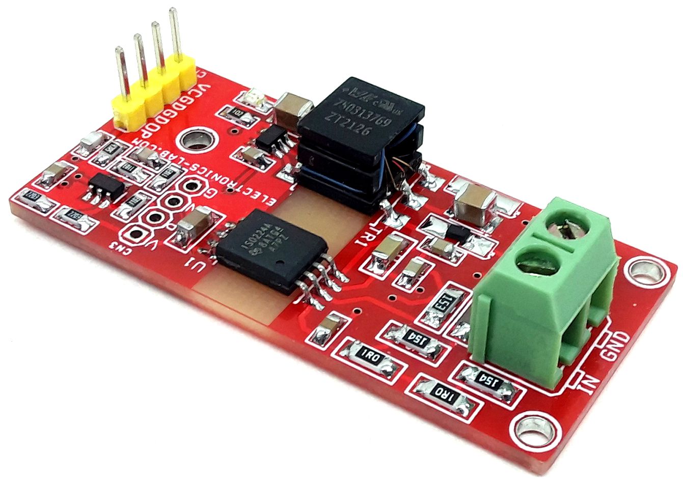
250V AC Isolated Voltage-Sensing Circuit with Single output (250V AC Input 5V Output)
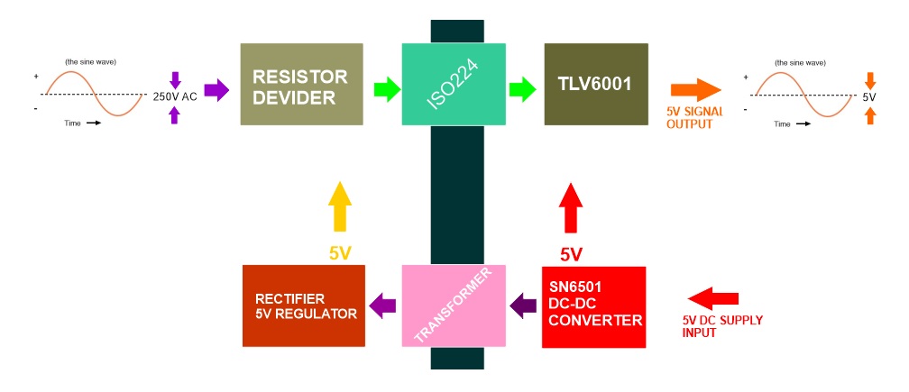
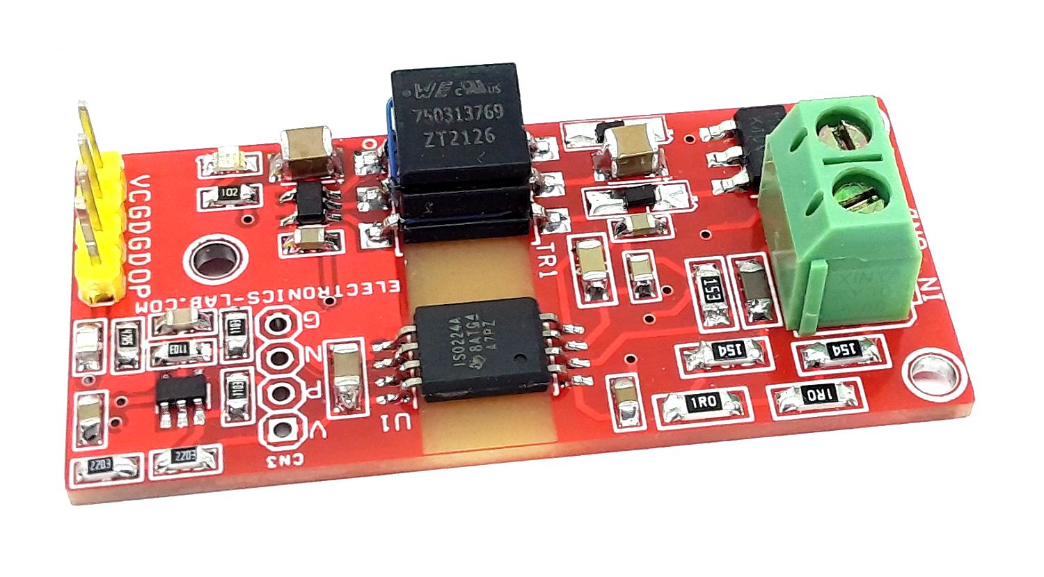
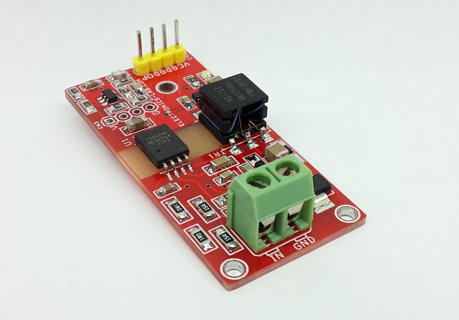
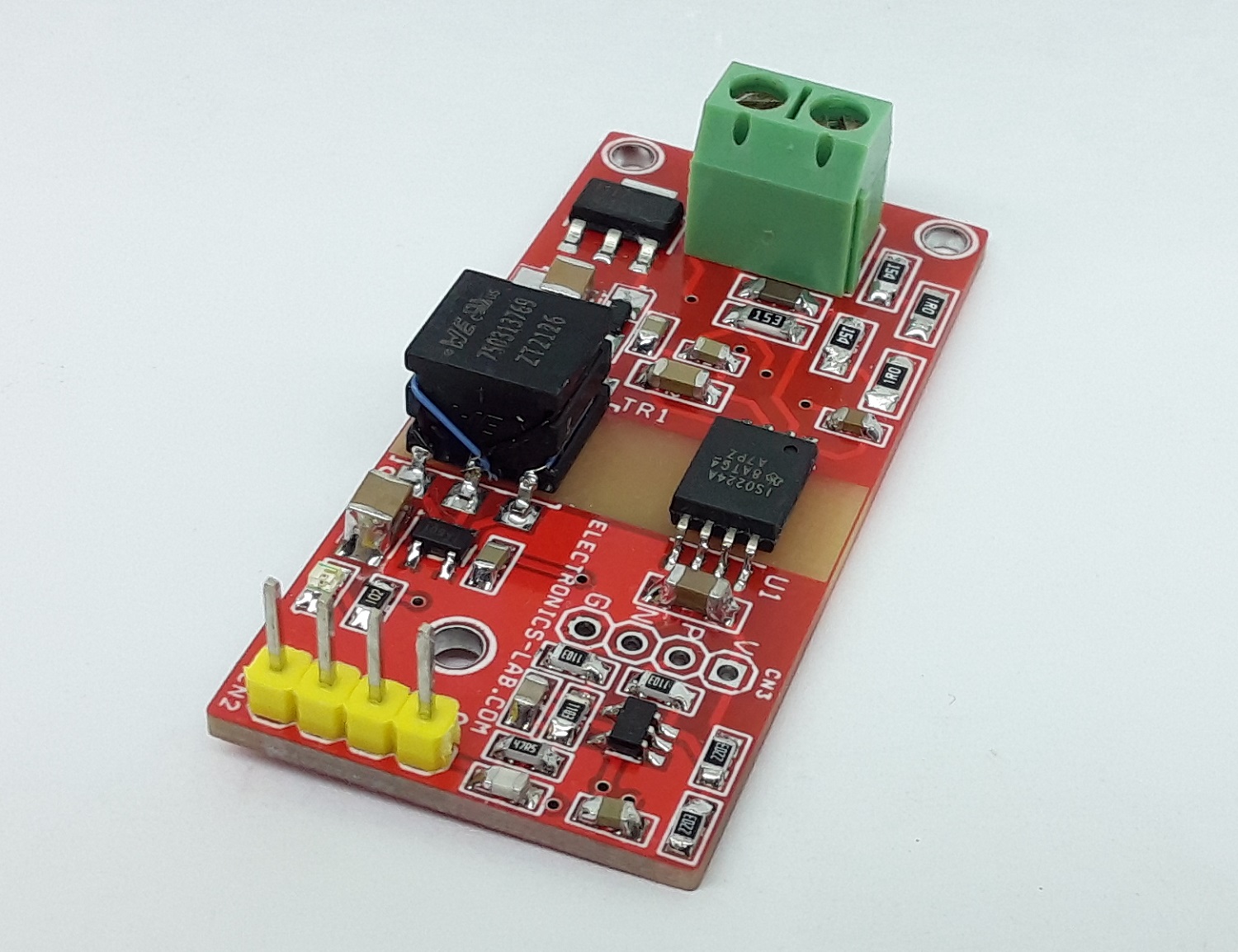
The project presented here can be used in isolated voltage sensing measurements applications. The board was built using ISO224B isolated amplifier, isolated 5V DC-DC converter provides 5V DC to the input side of ISO224 amplifier, TLV6001 op-circuit converts the differential signal of ISO224 and provides single-ended output. The circuit measures the 250V AC voltage and outputs a 5V signal, the output is optically isolated and the output voltage will change proportional to the input voltage. The operating supply of the project is a single 5V DC. The divider resistor reduces the voltage from AC 250V to +/-7.5V which is within the input range of ISO224 (+/-12V). The circuit can be used to measure the DC voltage as well AC voltage.
Features
- Operating Supply 5V DC
- Onboard Isolated 5V to 5V DC-DC Converter to Power The input Side of ISO224 Amplifier
- Input 250V AC
- Frequency Response 1Hz to 20Khz (Tested)
- Can be Configured to Measure the DC +/-7.5V DC or Higher
- Can be Configured for differential Output
- Output 5V
- Onboard Power LED
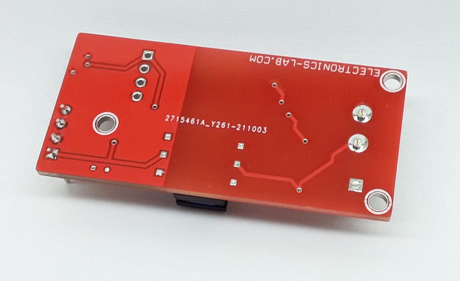
- PCB Dimensions 53.50 x 25.24 mm
AC Voltage Measurement
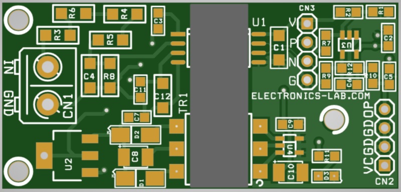
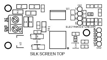
The existing circuit can measure the AC voltage up to 250V AC and provide a 5V sinewave, output level depends on the input voltage level. When the input is off, the output is 2.5V DC. Users may change the input to output ratio by altering input divider resistors R3, R4, R5, R6, and R8. It is recommended to use 1% tolerance for all these resistors, C4 is to prevent the noise coming from input. This board can be configured to measure the +/-480V by altering the values of the divider resistors.
DC Voltage Measurement
This circuit can measure dual input +/-7.5V DC and provides 0 to 5V DC (2.5V DC when input is Zero or OFF). When R3, R4, R5, R6, resistor values are 0 Ohms and R8 is not used. For higher voltage measurement use appropriate divider resistors R3, R4, R5, R6, R8. It is important to maintain a maximum output of +/-7.5V after divider resistors.
Differential Output for ADC Interface
Make the following changes to configure this board for differential output
- Do not Install R1, R2, R10, R7, R9, R12, C6, C5, U3, CN2
- Use CN3 for the interface: Pin 1 VCC-5V DC input, Pin 2 +P Output for ADC, Pin 3 -N Output for ADC, Pin 4 GND
- R3, R4, R5, R6 = 0 Ohms 1206 size, do not install R8
- Project Provides differential output +/-4V with input +/-12V
- Calculate and Choose divider resistor R3, R4, R5, R6, and R8 for higher voltage measurements
This board can be configured for differential output which is important for analog-to-digital converters (ADC) interface. ISO224 is optimized for accurate sensing of +/-12V signals that are widely used in industrial applications. Do not populate the following components R1, R2, R10, R7, R9, R12, C6, C5, U3, CN2 to optimize the board for differential output. Optional Connector CN3 helps for the ADC interface.
The ISO224 is a precision isolated amplifier with an output separated from the input circuitry by an isolation barrier with high immunity to magnetic interference. This barrier is certified to provide reinforced galvanic isolation of up to 5 kVRMS with an exceptionally long lifetime and low power dissipation. When used with isolated power supplies, this device separates parts of the system that operate on different common-mode voltage levels and protects lower-voltage devices from damage. The input of the ISO224 is optimized for accurate sensing of ±10-V signals that are widely used in industrial applications. The device operates of a single supply on the high side. This unique feature simplifies the design of the isolated power supply and reduces the system cost. The integrated high-side supply voltage detection feature simplifies system-level diagnostics. The ±4-V output of the ISO224 allows lower-cost analog-to-digital converters (ADCs) to be used. The differential structure of the output supports high immunity to noise.
Schematic
Parts List
| NO. | QNTY. | REF. | DESC. | MANUFACTURER | SUPPLIER | PART NO |
|---|---|---|---|---|---|---|
| 1 | 1 | CN1 | 2 PIN SCREW TERMINAL PITCH 5.08MM | PHOENIX | DIGIKEY | 277-1247-ND |
| 2 | 1 | CN2 | 4 PIN MALE HEADER PITCH 2.54MM | WURTH | DIGIKEY | 732-5317-ND |
| 3 | 1 | CN3 | DNP | |||
| 4 | 2 | C1,C12 | 10uF/16V SMD SIZE 1206 | MURATA/YAGEO | DIGIKEY | |
| 5 | 4 | C2,C7,C9,C11 | 0.1uF/50V SMD SIZE 0805 | MURATA/YAGEO | DIGIKEY | |
| 6 | 1 | C3 | 0.22uF/50V SMD SIZE 0805 | MURATA/YAGEO | DIGIKEY | |
| 7 | 2 | C4,C5 | 100PF/50V SMD SIZE 0805 | MURATA/YAGEO | DIGIKEY | |
| 8 | 1 | C6 | 33PF/50V SMD SIZE 0805 | MURATA/YAGEO | DIGIKEY | |
| 9 | 2 | C8,C10 | 10uF/16V SMD SIZE 1210 | MURATA/YAGEO | DIGIKEY | |
| 10 | 2 | D1,D2 | PD3S120L-7 | DIODE INCORP | DIGIKEY | PD3S120LQ-7DICT-ND |
| 11 | 1 | D3 | LED SMD SIZE 0805 | OSRAM | DIGIKEY | 475-1278-1-ND |
| 12 | 2 | R1,R2 | 220K 1% SMD SIZE 0805 | MURATA/YAGEO | DIGIKEY | |
| 13 | 3 | R3,R4,R5 | 150K 1% SMD SIZE 1206 | MURATA/YAGEO | DIGIKEY | |
| 14 | 1 | R6 | 1E 5% SMD SIZE 1206 | MURATA/YAGEO | DIGIKEY | |
| 15 | 3 | R7,R9,R12 | 105K 1% SMD SIZE 0805 | MURATA/YAGEO | DIGIKEY | |
| 16 | 1 | R8 | 10K % SMD SIZE 1206 | MURATA/YAGEO | DIGIKEY | |
| 17 | 1 | R10 | 47E 5% SMD SIZE 0805 | MURATA/YAGEO | DIGIKEY | |
| 18 | 1 | R11 | 1K 5% SMD SIZE 0805 | MURATA/YAGEO | DIGIKEY | |
| 19 | 1 | TR1 | 750313769 TRANSFORMER | WURTH | DIGIKEY | 1297-1107-1-ND |
| 20 | 1 | U1 | ISO224B | TI | DIGIKEY | 296-52316-1-ND |
| 21 | 1 | U2 | LM1117-5V | TI | DIGIKEY | LM1117MPX-5.0CT-ND |
| 22 | 1 | U3 | TLV6001IDBVR | TI | DIGIKEY | 296-TLV6001IDBVRCT-ND |
| 23 | 1 | U4 | SN6501 | TI | DIGIKEY | 296-30388-1-ND |
Block Diagram
Connections
Input vs Output
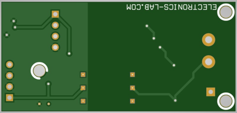
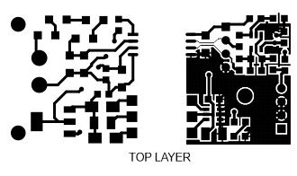
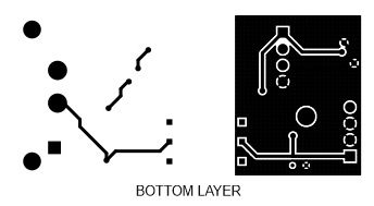
Gerber View
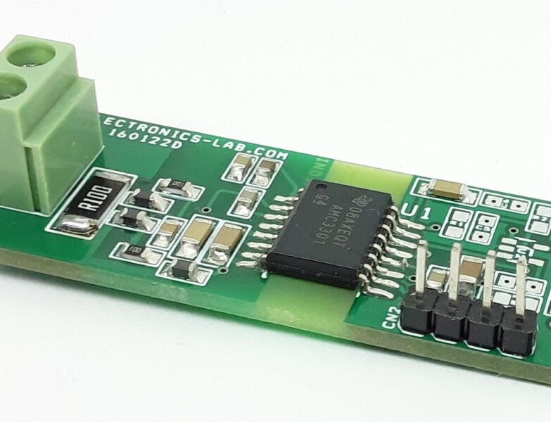
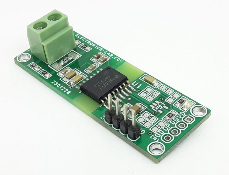
Photos
Video


