40 & 28 PIN PIC Development Board with ICSP interface
- Rajkumar Sharma
- 11.991 Views
- moderate
- Tested
- SKU: EL39218
- Quote Now
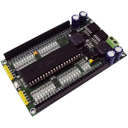
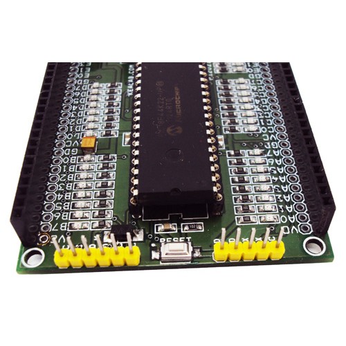
This is a PIC 40/28 PIN (DIP) PIC Development / Evaluation board that demonstrates the capabilities of Microchips 8-bit microcontrollers, specifically, 28- and 40-pin PIC16FXXX, PIC16F1XXX, and PIC18 devices. It can be used as a standalone demonstration board with a programmed part. With this board, you can develop and prototype using all Microchip’s 40 & 28 PIN PIC microcontrollers that don’t require external crystals (External Oscillator). The on-board connector for UART (RX-TX) allows an easy connection with embedded hardware and peripherals. The board has a RESET switch and status LEDs.
An on-board 3.3 V and 5V DC converter allow using 3V or 5V PICS as this board supports both 3.3V low power and normal 5V operation. All I/O Pins out with female header and male header connectors.
Specifications
- Power Supply 7V to 36V DC @ 3 Amps
- 40 PIN PIC18F46K22 & 28PIN PIC18F26K22 DIP Microcontrollers
- The PIC development platform is exclusively designed to offer full experimenting flexibility to a developer or application engineer for the enhanced range of 28/40 pin 8 bit PIC Microcontroller.
- Industrial standard 3A Switching regulator brings in safe operation of the board for all types of input supply without overheating.
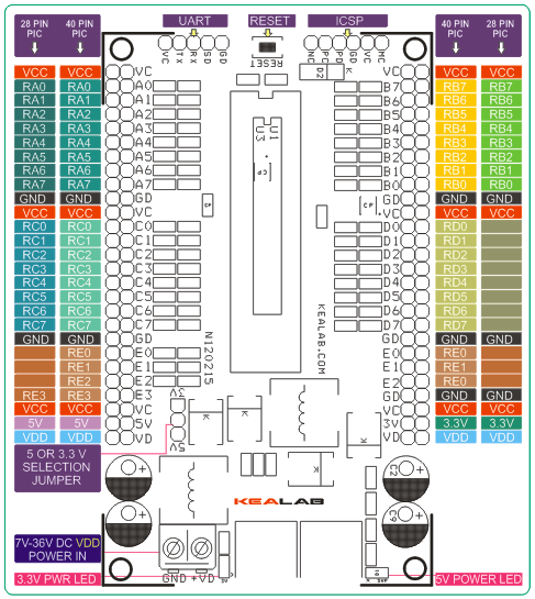
- Dual supply (5.0V and 3.3V @ 3A) takes care of all the supply needs of your IO devices and the operating voltage of the board. Independent Supply of 3.3V, 5V, and Input VDD (Input Supply) is always available at header pins.
- With a single Jumper, you can select the operating voltage of the MCU between 5.0 and 3.3 V
- PICKIT2 standard ICSP interface is available for ease of programming.
- Separate IO pins for the UART interfacing available for Serial interfacing.
- A LED circuit on every IO pin of the MICRO to give you an easy visual status of the pins. Optional and not provided along with the kit.
- Separate PWR ON indicator for each of the 2 supply (3.3V / 5V) available.
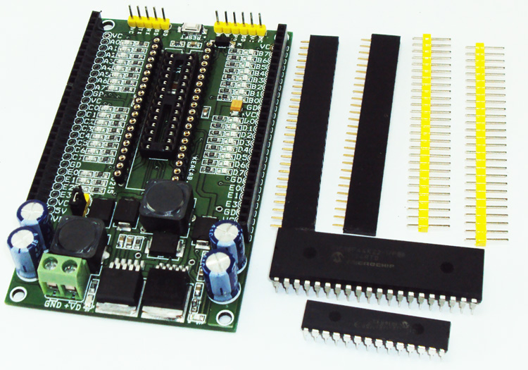
- Dual Header connector, Male/Female available for ease of interfacing with the outside world
- RESET switch to reset the onboard MCU.
- Supply reverse input diode for protection at both 3.3V and 5V DC-DC Converter inputs
Schematic



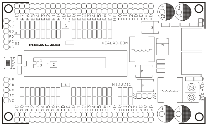
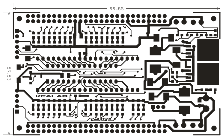
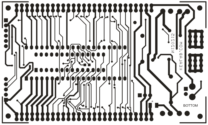


Hello and thanks for sharing this project. I am going to use this project as my school homework, but I have some questions about the schematics that i don’t understand. In the VCC and the capacitors section, Why did we use a lot of capacitors for the same pin? I am talking about c6-c7, c14-c15, and c16-c17 and VCC connection. And c19-c20 is also a part that i don’t understand. Isn’t it going to be parallel to each other? Or there is something that i am not seeing?
And in the regulator section, you used 1n5422 as schottky. But in my country, i can’t find any. Can you recommend an equivalent for it.
Thank you for your time.
HI,
i will email you the reply.
Hi, really nice design. I read that there is a kit available. Where can I get this kit? Is there a link? Thanks.
can thick be an alternative for PIC18F46K22 40pin?