434MHz Wireless LED Dimmer Transmitter – Arduino Compatible
- Rajkumar Sharma
- 14 Views
- moderate
- Tested
- SKU: EL156849
- Quote Now
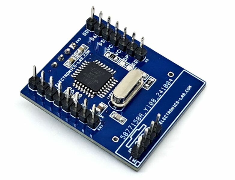
The project presented here is a 434MHz Wireless Transmitter for LED Dimmer, built around the ATMEGA328 Arduino microcontroller. The potentiometer is connected to the ADC A1 analog pin of the ATMEGA328 chip. The microcontroller reads the analog value of the potentiometer and transmits the data through the 434MHz RF module. This data is received at the receiver end, which controls the LED intensity using a PWM (Pulse Width Modulation) signal.
The project’s key components include:
- ATMEGA328 microcontroller: This microcontroller is responsible for reading the analog value from the potentiometer and transmitting it through the 434MHz RF ASK module connected to D2 pin of Arduino micro-controller.
- 434MHz ASK RF Transmitter module: This module is used to transmit the data from the microcontroller to the receiver.
- Connector for programming and bootloader: This connector allows for easy programming and updating of the microcontroller.
- Potentiometer: On board potentiometer connected to A1 ADC of ATMEGA328 microcontroller
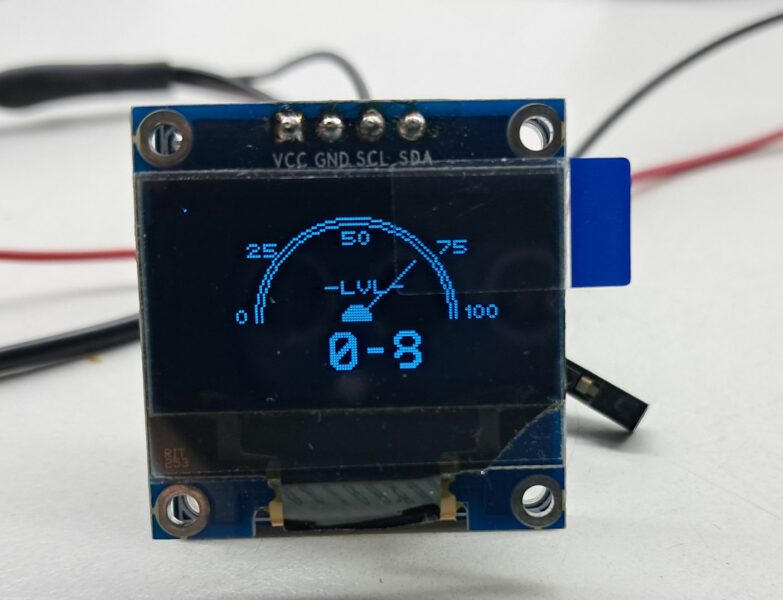
- Optional OLED installation: The project allows for the installation of an OLED display to display the analog transmit data (Not used in this project)
- Optional Connector for digital I/O D5 and D6: This connector provides additional digital I/O pins for future expansion.
- The system operates by reading the analog value from the pot, which ranges from 0 to 1023, and transmitting it through the 434MHz RF ASK module. The data can then be received and converted to PWM signal to control the intensity of LED, Lamp or speed control of DC brushed motor.
Features
- Power Supply 5V DC @ 50mA
- On Board RF434 Module Connector
- Very Compact Low-cost solution
- On Board Potentiometer (Analog value 0 to 1023)
- Optional OLED Display
- Optional 4 Pin Header Connector 2 Digital I/O D5 and D6
- 8 Pin Header Connector for Arduino Programming and Bootloader
- Temperature Sensor LM35 Can be directly Mount on PCB
- 4 x 4 mm Mounting Holes for PCB
- PCB Dimensions 50.80 x 26.83 mm
How it Works
The project operates as follows:
- The potentiometer is used to set the desired LED intensity.
- The ATMEGA328 microcontroller reads the analog value of the potentiometer through the ADC A1 pin.
- The microcontroller processes the analog value and converts it into a digital signal.
- The digital signal is transmitted through the 434MHz RF module to the receiver end.
- The receiver receives the transmitted data and uses it to control the LED intensity using a PWM signal.
Optional OLED Display
The project also features an optional 0.96-inch OLED display, which can be used to display the current LED intensity level or other relevant information. Overall, this project demonstrates a simple and effective way to wirelessly control LED intensity using a potentiometer and RF communication.
To test the project, an Arduino code is available for download, allowing users to read analog values on ADC A1 and transmit through a 434Mhz RF module.
The code can be modified to suit specific application requirements. It is important to note that a new ATMEGA328 microcontroller requires a bootloader before programming the Arduino code.
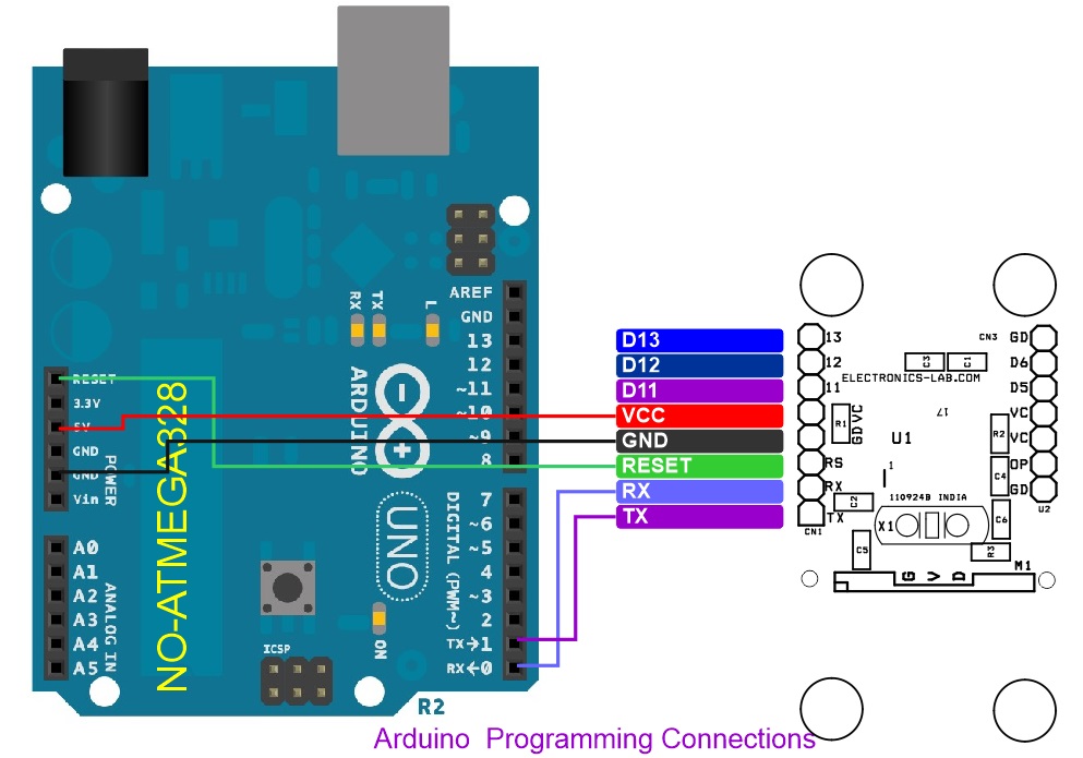
To facilitate this process, a connection diagram is provided for both bootloader and Arduino programming. Additionally, users can refer to the official Arduino documentation, specifically the “Arduino to Breadboard” example, for more information on Arduino programming and bootloader installation.
The provided link to the Arduino documentation (https://docs.arduino.cc/built-in-examples/arduino-isp/ArduinoToBreadboard/) offers a comprehensive guide on how to program the ATMEGA328 microcontroller and install the bootloader, ensuring seamless integration with the Wireless LED dimmer.
This Transmitter Project is compatible with the 434Mhz Wireless Receiver – LED Dimmer
Connections
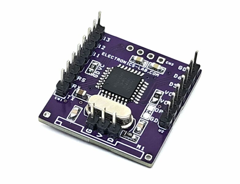
- CN1 Programming Connector: Pin 1 = TX, Pin 2 = RX, Pin 3 = Reset, Pin 4 = GND, Pin 5 = VCC, Pin 6 = D11, Pin 7 = D12, Pin 8 = D13
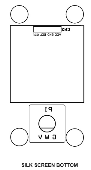
- CN2: OLED Display Optional 0.96Inc I/2C
- CN3: Optional I/O, Pin 1 = VCC, Pin 2 = D5, Pin 3 = D6, Pin 4 = GND
- U2 Analog Sensor: Pin 1 = VCC, Pin 2 Sensor, Pin 3 = GND
- M1: RF Module 434Mhz ASK Transmitter 3 Pin, Connected to D2 pin of microcontroller.
Schematic
Parts List
| NO | QNTY. | REF. | DESC | MANUFACTURER | SUPPLIER | SUPPLIER PART NO | |
|---|---|---|---|---|---|---|---|
| 1 | 1 | CN1 | 8 PIN MALE HEADER PITCH 2.54MM | WURTH | 732-5321-ND | ||
| 2 | 4 | U2,CN2,CN3,C4 | DNP | ||||
| 3 | 1 | C1 | 10uF/25V CERAMIC SMD SIZE 0805 | YAGEO/MURATA | |||
| 4 | 2 | C2,C3 | 0.1uF/50V CERAMIC SMD SIZE 0805 | YAGEO/MURATA | |||
| 5 | 2 | C5,C6 | 22PF/50V CERAMIC SMD SIZE 0805 | YAGEO/MURATA | |||
| 6 | 1 | M1 | RF AM Tx 434MHZ MODULE | EBAY/AMAZON | |||
| 7 | 1 | P1 | 10K POTENTIOMETER | TT ELECTRONICS | 987-1276-ND | ||
| 8 | 1 | R1 | 10K 5% SMD SIZE 0805 | YAGEO/MURATA | |||
| 9 | 1 | R2 | 0E 5% SMD SIZE 0805 | YAGEO/MURATA | |||
| 10 | 1 | R3 | 1M 5% SMD SIZE 0805 | YAGEO/MURATA | |||
| 11 | 1 | U1 | ATMEGA328TQPF-32 | MICROCHIP | ATMEGA328P-AU-ND | ||
| 12 | 1 | X1 | 16Mhz | ECS INC | X1103-ND |
Connections


