434Mhz Wireless Receiver – LED Dimmer – Arduino Compatible
- Rajkumar Sharma
- 11 Views
- moderate
- Tested
- SKU: EL156878
- Quote Now
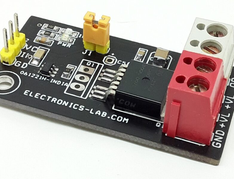
The Wireless Receiver Dimmer is a complementary component to the Wireless Potentiometer Transmitter, designed to receive and process data transmitted from the transmitter. This project can be used to drive the LED, Heater or brushed dc motor, and supports inductive or resistive loads. A gate driver chip MCP1416 is provided to drive the gate of MOSFET. Low ohmic MOSFET can drive inductive load up to 3A and resistive load up to 4A, don’t install D1 for 4A load.
Features
- Supply 12V DC
- 8 Pin Programming Connector
- On Board RF Receiver 434Mhz Module
- PWM Frequency 980Hz
- PWM Duty Cycle range 0 to 100%
- Low Ohmic MOSFET for high current and low heat
- PCB Dimensions 52.29 x 31.12 mm
Key Specifications
- Load capacity: up to 3A (inductive)
- Resistive load up to 4A, don’t install D1 in this case
- DC supply: 12V DC
The receiver system consists of:
- 434MHz RF ASK Receiver module: This module receives the data transmitted from the transmitter.
- Arduino microcontroller ATMEGA328: This microcontroller processes the received data and provides PWM signal output.
- PWM signal connected to the input of gate driver chip MCP1416
- MCP1416 Gate driver chip drives the N-type MOSFET
- D1 Diode: Freewheeling diode to drive the inductive load such as DC brushed motor.
- 0.96Inch OLED display: An optional OLED display can be used to display the dimmer level (Display is not used Here)
The system operates as follows:
- The 434MHz RF ASK Receiver module receives the data transmitted from the transmitter.
- The microcontroller, ATMEGA328, receives the data on digital pin D12.
- The microcontroller processes the received data and extracts the analog value.
- The processed analog value and converted to PWM signal
- This PWM signal drive the MOSFET help of gate driver chip.
The receiver also features:
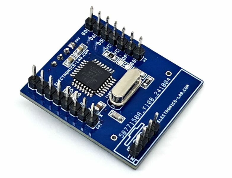
- 8-pin header connector for bootloader and Arduino programming: This connector allows for easy programming and updating of the microcontroller.
- Optional 4-pin connector with 2 x I/O D5 and D6: This connector provides additional digital I/O pins for future expansion or customization.
- The Wireless Receiver for the LED dimmer is a cost-effective solution for receiving and controlling the intensity of LED, making it an ideal component for various applications that require remote control of LED dimmer or motor speed.
The Wireless LED Dimmer Receiver project is accompanied by a transmitter module, which can be accessed through the provided link.
Inductive Load and Resistive Load
- D1 Diode for Inductive Loads: The D1 diode, often referred to as a flyback diode or freewheeling diode, is crucial when driving inductive loads such as brushed DC motors. Its primary function is to provide a path for the inductive current to flow when the MOSFET switches off, preventing a high voltage spike that could damage the MOSFET. For inductive loads, this diode is essential for protecting your MOSFET.
- LED or Resistive Load: For loads that are not inductive, such as LEDs or purely resistive loads (like heaters or resistors), the flyback diode is not necessary. This is because these types of loads do not produce the same kind of voltage spikes when the current is interrupted.
- Current Limitation Without Diode: The project can drive loads up to 4A without the diode D1.
- Fan Cooling for MOSFET: The advice to use fan cooling for the MOSFET is a good practice, especially if you’re operating near the maximum current limits of the device. MOSFETs can dissipate a significant amount of power as heat.
This receiver board is compatible with the 434MHz Wireless LED Dimmer Transmitter we previously published.
To test the project, an Arduino code is available for download, allowing users to receive and control the intensity of LED or speed of motor.
The code can be modified to suit specific application requirements, and users can map the analog value for proper representation of motor speed or LED intensity. It is important to note that a new ATMEGA328 microcontroller requires a bootloader before programming the Arduino code.
To facilitate this process, a connection diagram is provided for both bootloader and Arduino programming. Additionally, users can refer to the official Arduino documentation, specifically the “Arduino to Breadboard” example, for more information on Arduino programming and bootloader installation.
The provided link to the Arduino documentation (https://docs.arduino.cc/built-in-examples/arduino-isp/ArduinoToBreadboard/) offers a comprehensive guide on how to program the ATMEGA328 microcontroller and install the bootloader, ensuring seamless integration with the Wireless Analog Sensor Receiver project.
Ensure that you have the necessary libraries installed in your Arduino IDE, before uploading the code to Arduino Micro-controller ATMEGA328.
Connections
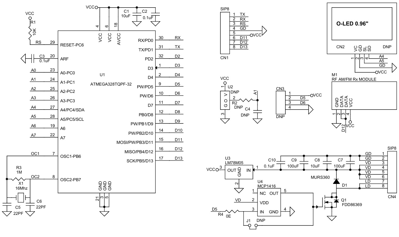
- CN1 Bootloader/Arduino Programming: Pin 1 = TX, Pin 2 = RX, Pin 3 = Reset, Pin 4 = GND, Pin 5 = VCC, Pin 6 = D11, Pin 7 = D12, Pin 8 = D13
- CN4: Pin 1,2 = GND, Pin 3,4= VDD 12V DC, Pin 5,6 = VDD 12V Load +, Pin 7,8 = Load –
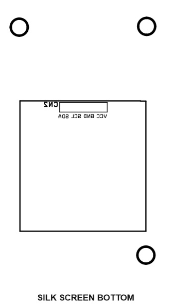
- CN2, CN3: No Use.
Schematic
Parts List
| NO. | QNTY. | REF. | DESC. | MANUFACTURER | SUPPLIER | SUPPLIER PART NO |
|---|---|---|---|---|---|---|
| 1 | 2 | CN1,CN4 | 8 PIN MALE HEADER PITCH 2.54MM | WURTH | DIGIKEY | 732-5321-ND |
| 2 | 6 | J1,U2,R2,CN2,C4,CN4 | DNP | |||
| 3 | 1 | C1 | 10uF/16V CERAMIC SMD SIZE 0805 | YAGEO/MURATA | DIGIKEY | |
| 4 | 3 | C2,C3,C10 | 0.1uF/50V CERAMCI SDM SIZE 0805 | YAGEO/MURATA | DIGIKEY | |
| 5 | 2 | C5,C6 | 22PF/50V CERAMIC SMD SIZE 0805 | YAGEO/MURATA | DIGIKEY | |
| 6 | 2 | C7,C9 | 100uF/16V CERAMIC SMD SIZE 1210 | YAGEO/MURATA | DIGIKEY | |
| 7 | 1 | D1 | MURS360 FAST DIODE | ONSEMI | DIGIKEY | MBRS360T3GOSCT-ND |
| 8 | 1 | M1 | RF AM 434MHZ Rx MODULE | CHINA | ||
| 9 | 1 | Q1 | FDD86369 DPAK | ON SEMI | DIGIKEY | FDD86369OSCT-ND |
| 10 | 1 | R1 | 10K 5% SMD SIZE 0805 | YAGEO/MURATA | DIGIKEY | |
| 11 | 1 | R3 | 1M 5% SMD SIZE 0805 | YAGEO/MURATA | DIGIKEY | |
| 12 | 1 | R4 | 0E SMD SIZE 0805 | YAGEO/MURATA | DIGIKEY | |
| 13 | 1 | U1 | ATMEGA328TQPF-32 | MICROCHIP | DIGIKEY | ATMEGA328P-AU-ND |
| 14 | 1 | U3 | LM78M05 | TI | DIGIKEY | MC78M05CDTGOS-ND |
| 15 | 1 | U4 | MCP1416 | MICROCHIP | DIGIKEY | MCP1416RT-E/OTCT-ND |
| 16 | 1 | X1 | 16Mhz | ECS INC | DIGIKEY | X1103-ND |
| 17 | 1 | C8 | 10uF/16V CERAMIC SMD SIZE 1206/1210 | YAGEO/MURATA | DIGIKEY |
Connections


