5V to 12V Step Up DC-DC Converter
- Rajkumar Sharma
- 147.909 Views
- easy
- Tested
- SKU: EL48236
- Quote Now
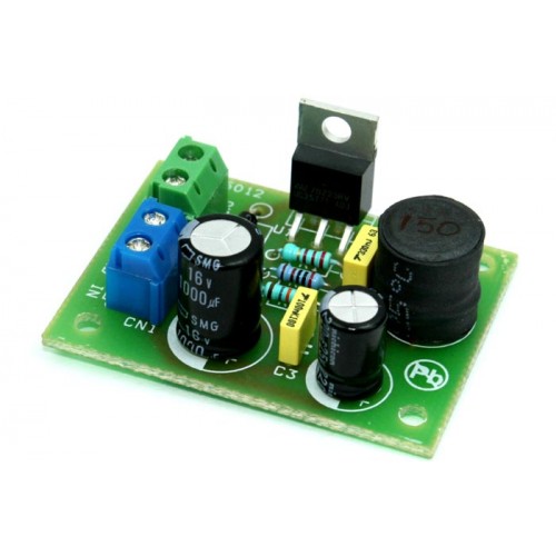
Step up DC-DC converter is based on LM2577-ADJ IC, this project provides 12V output using 5V input, maximum output load of 800mA. The LM2577 are monolithic integrated circuits that provide all of the power and control functions for step-up (boost), fly-back, and forward converter switching regulators. The device is available in three different output voltage versions: 12V, 15V, and adjustable.
Requiring a minimum number of external components, these regulators are cost-effective, and simple to use. Listed in this data sheet are a family of standard inductors and fly-back transformers designed to work with these switching regulators. Included on the chip is a 3.0A NPN switch and its associated protection circuitry, consisting of current and thermal limiting, and under voltage lockout. Other features include a 52 kHz fixed-frequency oscillator that requires no external components, a soft start mode to reduce in-rush current during start-up, and current mode control for improved rejection of input voltage and output load transients.
Features
- Requires Few External Components
- Input 5V DC
- Output 12V DC
- Output Load 800mA
- Current-mode Operation for Improved Transient Response, Line Regulation, and Current Limit
- 52 kHz Internal Oscillator
- Soft-start Function Reduces In-rush Current During Start-up
- Output Switch Protected by Current Limit, Under-voltage Lockout, and Thermal Shutdown
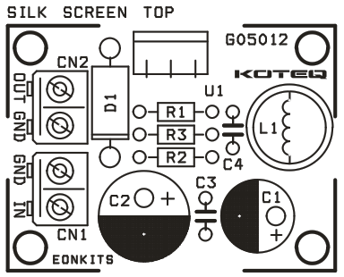
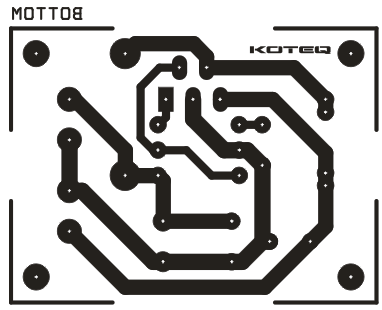
- PCB Dimensions: 45.72 x 34.29 mm
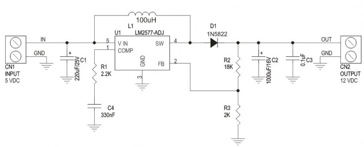
Project is based on LM2577-ADJ IC for flexibility to obtain other output voltages by changing value of feedback resistors R2 and R3
Output Voltage Formula V Out=1.23V (1+R2/R3) (Read DataSheet for more information about Inductor value, Capacitor, Feedback resistors, Output current and voltage)
Schematic
How It Works
LM2577 turns its output on and off at a frequency of 52 KHz, and this creates energy in the inductor L1.
When the NPN switch turns on, the inductor current charges up at a rate of vin/L1, storing current in the inductor. When the switch turns off,, the lower end of the inductor flies above Vin, discharging its current through diode into the output capacitor at rate of (Vout-Vin)/L1. Thus energy stored in the
inductor during the switch on time is transferred to the output during the switch off time. The output voltage is controlled by amount of energy transferred which , in turn, is controlled by modulating the peak inductor current. This is done by feeding back portion of the output voltage to the error amp, which amplifies the difference between the feedback voltage and a 1.23V reference. The error amp output voltage is compared to a voltage proportional to the switch current ( ie., inductor current during the switch on time)
The comparator terminates the switch on time when the two voltages are equal, thereby controlling the peak switch current to maintain a constant output voltage.




how go buy this item
Please check on http://www.koteq.com for kits of our projects.
is it really working sir? i badly needed one. Thanks 🙂
This is a tested project. Thanks
What will be the PCB dimensions and diode 1N5822 is not available will Diode 1N5819 will do? Plus SMD Capacitor 330nf 1206 is this ok?
Try to print the PCB from the PDF file and it will be in correct dimensions. The diode used in this project is rated at 3A but the diode you mention is rated at 1A so there is possibility of damaging the diode on full output. Capacitor C4 should work fine.
sir can you kindly show the pictures of LM2577ADJ
Photo of the IC here: http://klinikrobot.com/components/com_virtuemart/shop_image/product/LM2577_ADJ_Simpl_55750748ea317.jpg
why am I getting same voltage at output which I’m applying at input.
This means that the IC isn’t oscillating. Please check for damaged parts and shorts.
Sir how to convert 5v in variable voltages using R1 and R2
I would suggest to read the LM2577-ADJ datasheet on how to change the output voltage. Output voltage is controlled using R2/R3 resistors of the schematic above.
Can i use for 12 volt 10 watt led light to 5 volt power input ???
If you LED draws less than 800mA then you can safely use this 5V to 12V converter to power the LED.
what happen when the load draw more than 800mA
You will probably see a voltage drop on output and maybe overload protection will engage.
Im just asking what voltage size should C3 and C4 be?
C3 should be at least 16V and C4 10V
Dear, where can i find the dimensions of the printboard?
Thanks!
Hi, Dimension for this PCB 45.72X34.29MM
I’ve updated the project with PCB dimensions.
SALUDOS DESDE VENEZUELA HERMANO…!!! Una pregunta tienes por casualidad elaborado un proyecto, o pudieras realizarlo, para covertir el voltaje de dos pilas AAA(1,5 Volt. C/U) a 9 Volt. Se trata de poner a funcionar un Micrófono inalámbrico que usa batería de 9 Volt con las dos baterías AAA, ya que en nuestro país esta batería de 9 Volt es muy dificil de conseguir y al conseguirla es muy costosa…!!! Gracias por su respuesta amigo. DIOS TE BENDIGA Y TE CUIDE CON TU BELLA FAMILIA…!!!
Could you post in English, please?
i wanna use it for laptop cooler fan can it damage the laptop ?
You can use this one https://www.electronics-lab.com/project/usb-12v-boost-converter/ which is designed for the USB port and it’s safe to use.
what to do to get 200mA output current
Can i use it to convert 5v charger output to power an led strip?
Yes, but it depends how much current the led strip draws. This board can provide up to 800mA.
Where can i get the pcb printed
We provide the files to build your own PCB. Would you like to get Gerber files as well?
5m of led strip use 2A i am using only 1.5 so will it work. If it won’t then please tell the solution
This board can provide 12V @ 800mA, so it will not be able to fully power the LEDs.
sir will it burn the board?
Please share the gerber files
Gerber files added above. Thanks
If i want 1A output then what can i do
You need to search for another board with more output current.
Can you build this project on a breadboard?
Sure, just keep the components close together.
Hello sir, can you tell what kind of inductor you use?
Can you send a dattasheet?
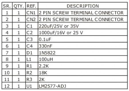
Check on datasheet above, at page 19 a list of inductors that are suitable for this board. Especially check for L100, there are 3 manufacturers listed.
Sir i really wanna creat this circuit for my storm robot, please tell me “does it really work”.
Yes, this is a tested project.
Any way I do love your design
Thanks for visiting!
Hello, can you tell me is the out current the same as input?
No, the input current will be higher than the output one, to preserve the power reservation.
Please sir , can this circuit power a 12 volt DC motor
How much current the motor needs?
6-12 volts sir
May I know the current drawn at 5V Input when 12V Output is at Max 800mA? Current drawn is 1.9A at 5V Input?
Yes, it should be ~2A, but best way is to measure it on actual board.
Is there a current place to purchase this PCB?
How many pieces do you need ?
Am I able to purchase this product anywhere?
We can produce this on order, the minimum is 8 boards and the lead time is 2-3 weeks. Thanks
And if I were to order 8 what would the cost and shipping be to U.S. area code18071?
Check your email for a quote.
Do you sell complete finished 5V t0 12V converter? How much will it be for 20pcs?
Check your email please.
Thank you for this very helpful article!
Is the LM2585 equivalent to the LM2577? It seems to be newer replacement part.
I’m not sure if it is a drop in replacement or if I need to change the values for the passive components.
Can you please help me?
Thank you
I think it’s not a direct replacement, as you may need to use LM2585-12 to convert 5V to 12V, and no feedback resistors on output according to the datasheet. You may check these alternatives: