AC Voltage Zero Cross Detector
This project provides AC voltage zero-cross timing detection and a DC voltage after diode rectification with high accuracy. Possible applications for such circuits are AC motor controllers, AC lamp controllers, AC Dimmer Controllers, Home Appliances. The circuit outputs a zero-cross signal from 90 Vac to 264 Vac input. The project is based on BM1Z102FJ chip which outputs a high precision zero-cross timing of targeted AC voltage and a DC voltage after diode rectification of high accuracy. The project also includes high voltage offline AC to DC converter chip BM2P129TF.
AC Voltage Zero Cross Detection
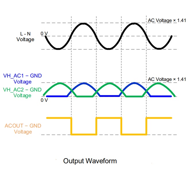
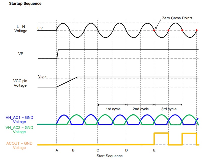
By monitoring the voltage between the VH_AC1 and VH_AC2 pins, this IC outputs the zero-cross point of AC voltage from the ACOUT pin. These pins have a built-in monitor circuit that tolerates 600 V and they realize high reliability and low power consumption. The ACOUT pin performs an N channel open-drain output and this makes it possible to support various applications. It is necessary for the VH_AC1 pin to be connected to the N side of the AC input and for the VH_AC2 pin to be connected to the L side of the AC input
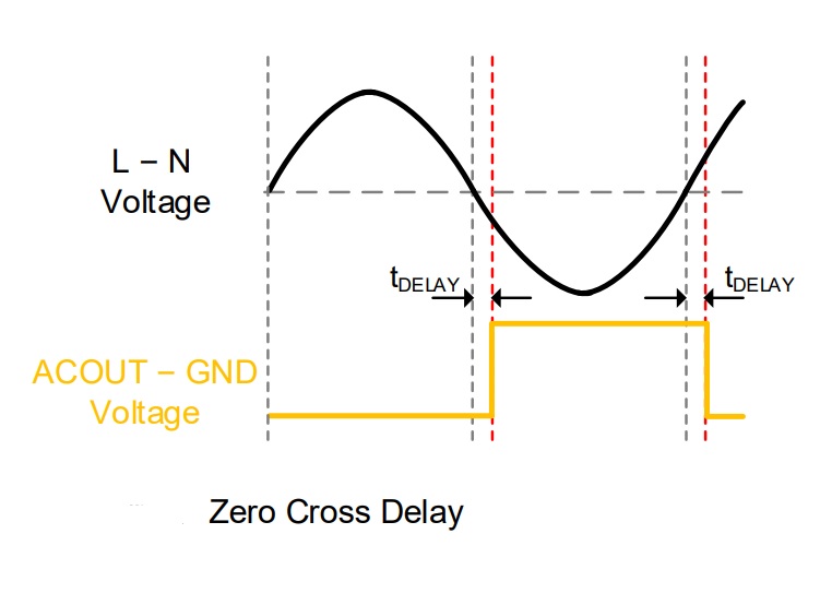
Output Delay Setting (DSET Pin Setting) – Resistor R7
- R7 OPEN DELAY 0uS
- R7 330K 200uS
- R7 68K -200uS
- R7 0 OHMS -480uS
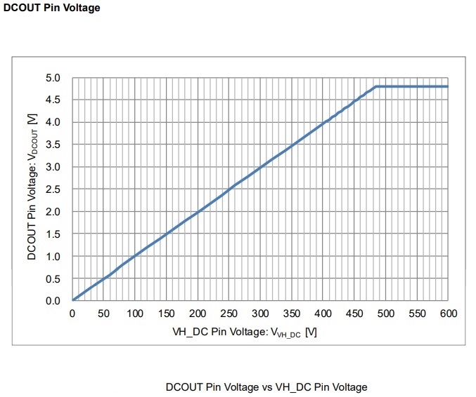
DC Out (DO) CN4 Pin 4
- 110V AC Outputs 1.1V DC
- 230V AC Outputs 3.3V DC
Safety Note
This board works with mains high voltage contains lethal voltage and should be handled only by qualified personnel familiar with all safety and operating procedures. Board contains parts that store significant charges even after disconnecting from the power source. Please discharge the capacitors after using the board, and please deal with it after confirming such electric discharge.
Be careful to not allow conductive objects to come into contact with the board. DO NOT touch the board with your bare hands or bring them too close to the board. In addition, as mentioned above please exercise extreme caution when using conductive tools such as tweezers and screwdrivers.
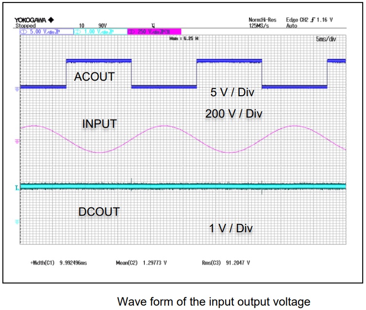
Input-Output Waveforms
Features
- Supply Input 90V AC to 264V AC
- On Board AC to DC Offline Converter (90VAC-264V AC input, 12V DC Output @ 100mA)
- DC Output about 1/100 voltage Approx. 1.1V with 110V AC, 3.3V with 230V AC input
- Input Frequency Response 47Hz to 63Hz
- Provides Accurate 50Hz Square wave with 230V/50Hz AC Input
- Default Output Pulse Delay time = 0uS (Can be Adjust Using R7)
- Aux DC Supply Output VCC-12V and 5V DC @ Maximum Load 100mA
- PCB Dimensions 58.90 x 28.73mm
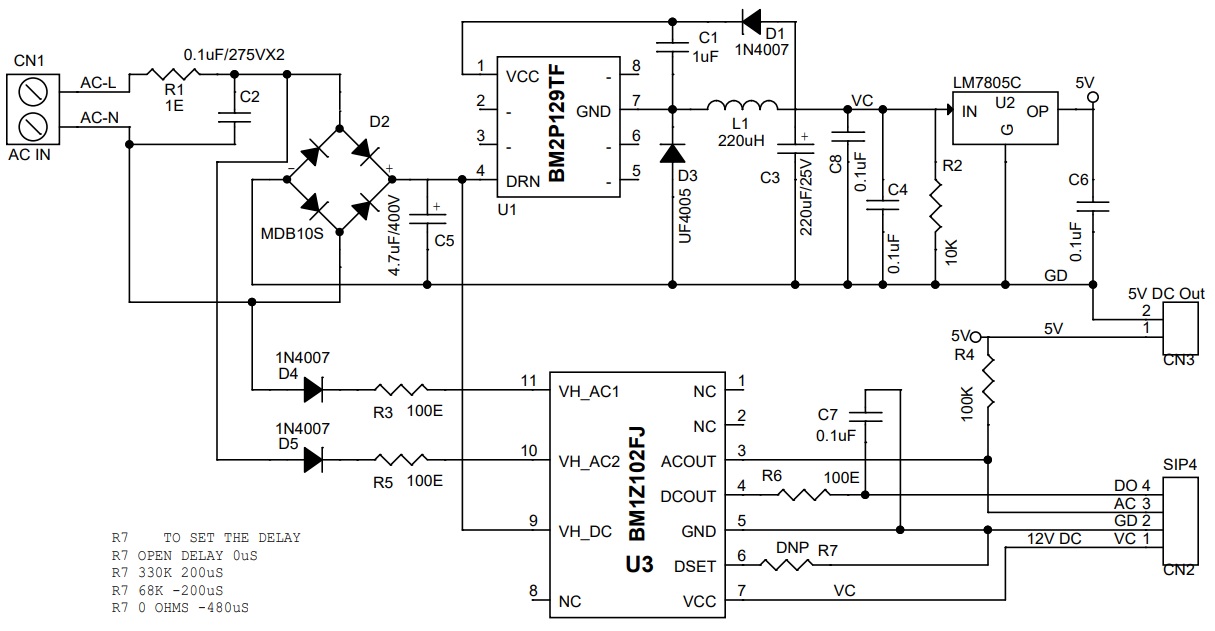
Schematic
Parts List
| NO | QNTY. | REF. | DESC. | MANUFACTURER | SUPPLIER | SUPPLIER PART NO |
|---|---|---|---|---|---|---|
| 1 | 1 | CN1 | 2 PIN SCREW TERMINAL | PHOENIX | DIGIKEY | 277-1247-ND |
| 2 | 1 | CN2 | 4 PIN MALE HEADER PITCH 2.54MM | WURTH | DIGIKEY | 732-5317-ND |
| 3 | 1 | CN3 | 2 PIN MALE HEADER PITCH 2.54MM | WURTH | DIGIKEY | 732-5315-ND |
| 4 | 1 | C1 | 1uF/25V SMD SIZE 0895 | MURATA/YAGEO | DIGIKEY | |
| 5 | 1 | C2 | 0.1uF/275VX2 | KEMET | DIGIKEY | 399-9651-ND |
| 6 | 1 | C3 | 220uF/25V | Wurth | DIGIKEY | 732-9026-1-ND |
| 7 | 4 | C4,C6,C7,C8 | 0.1uF/50V SMD SIZE 0805 | MURATA/YAGEO | DIGIKEY | |
| 8 | 1 | C5 | 4.7uF/400V | WURTH | DIGIKEY | 732-8886-1-ND |
| 9 | 3 | D1,D4,D5 | 1N4007 | MICRO-COM | DIGIKEY | 1N4007MSTR-ND |
| 10 | 1 | D2 | MDB10S | ONSEMI | DIGIKEY | MDB10SFSCT-ND |
| 11 | 1 | D3 | UF4005 | VISHAY | DIGIKEY | UF4005-M3/54GICT-ND |
| 12 | 1 | L1 | 220uH | WURTH | DIGIKEY | 732-1696-1-ND |
| 13 | 1 | R1 | 1E 5% 2W SMD SIZE 2512 | MURATA/YAGEO | DIGIKEY | |
| 14 | 1 | R2 | 10K 5% SMD SIZE 0805 | MURATA/YAGEO | DIGIKEY | |
| 15 | 3 | R3,R5,R6 | 100E 5% SMD SIZE 0805 | MURATA/YAGEO | DIGIKEY | |
| 16 | 1 | R4 | 100K 5% SMD SIZE 0805 | MURATA/YAGEO | DIGIKEY | |
| 17 | 1 | R7 | OPEN/DNP | |||
| 18 | 1 | U1 | BM2P129TF | ROHM | DIGIKEY | BM2P129TF-E2CT-ND |
| 19 | 1 | U2 | LM7805 OR MC78M05 | ONSEMI | DIGIKEY | MC78M05CDTGOS-ND |
| 20 | 1 | U3 | BM1Z102FJ | ROHM | DIGIKEY | 846-BM1Z102FJ-E2CT-ND |
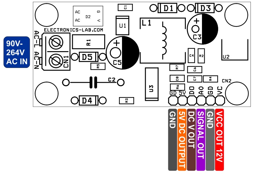
Connections
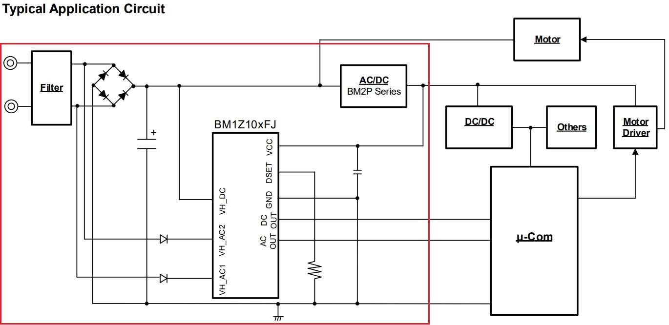
Application Circuit
Waveforms
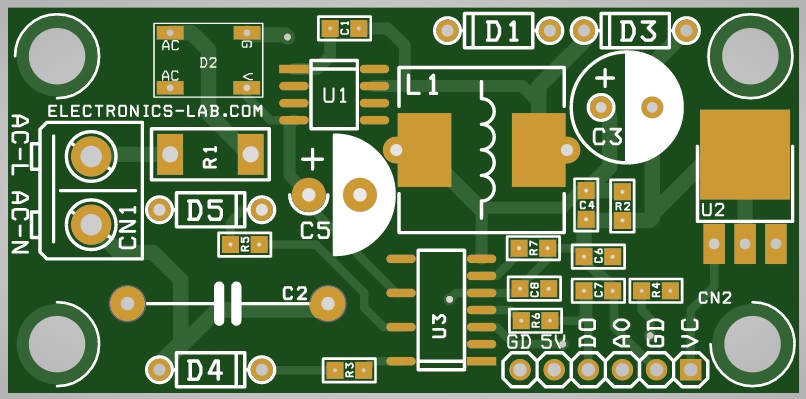
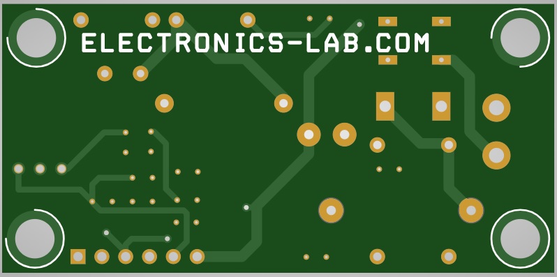
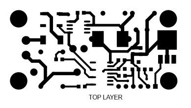
Gerber View
Photos


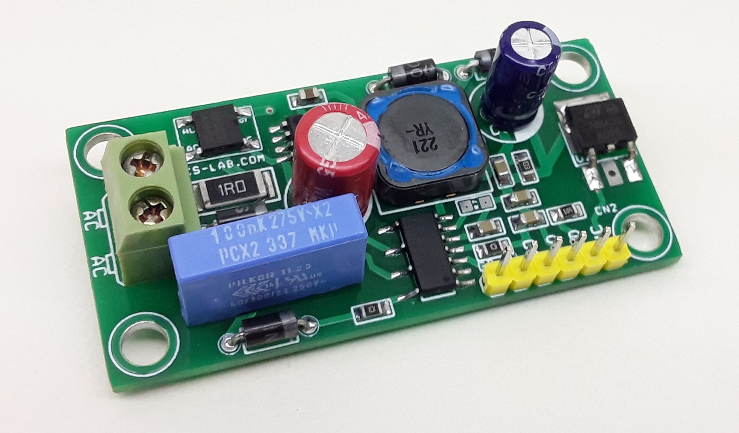

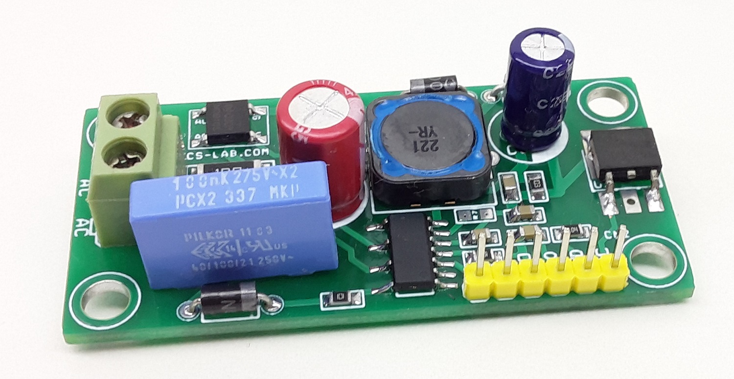
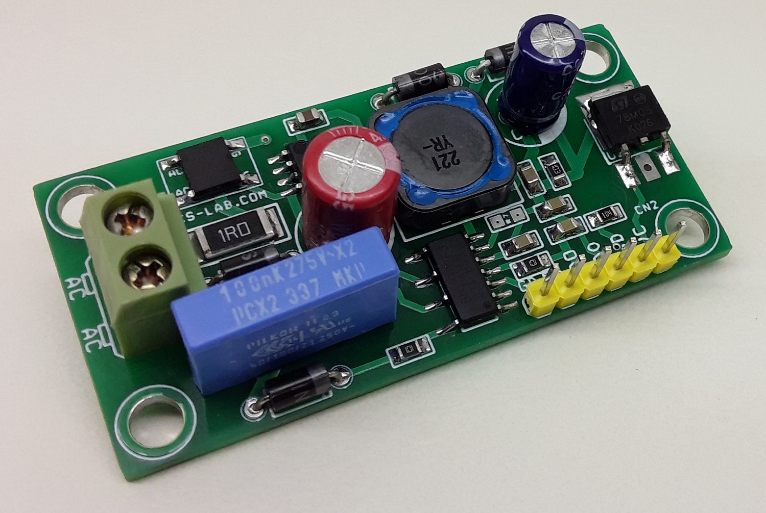
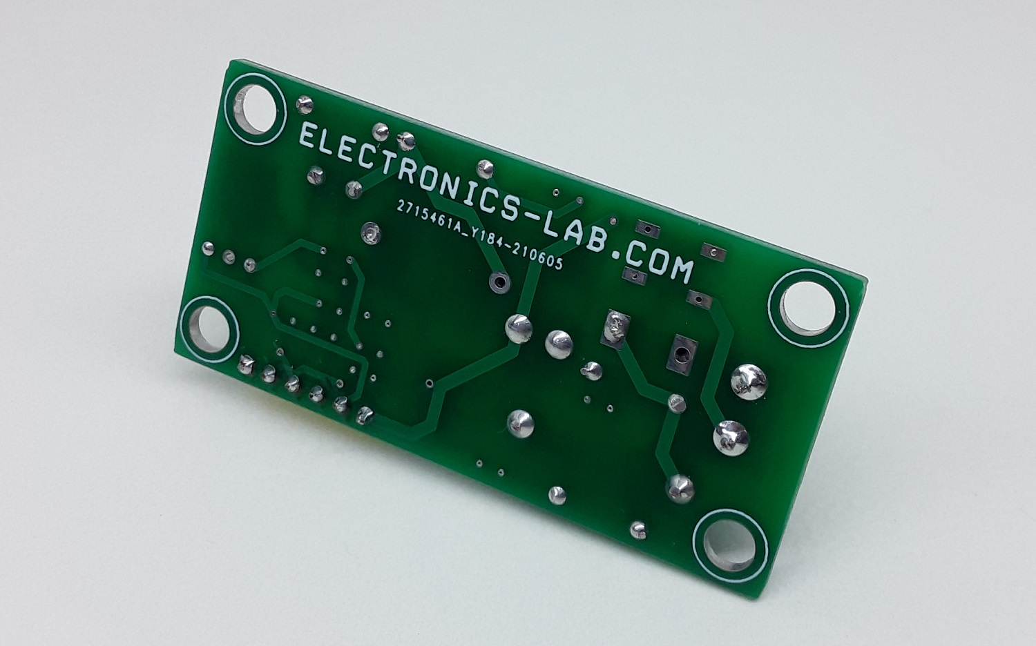
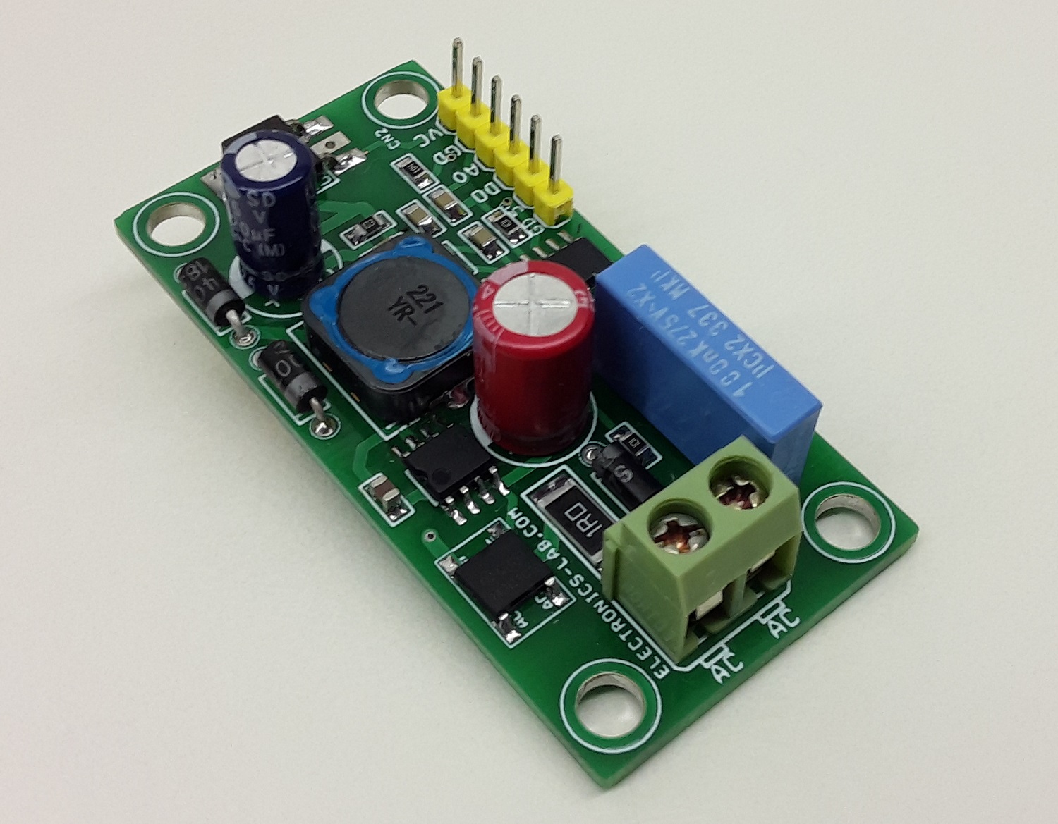
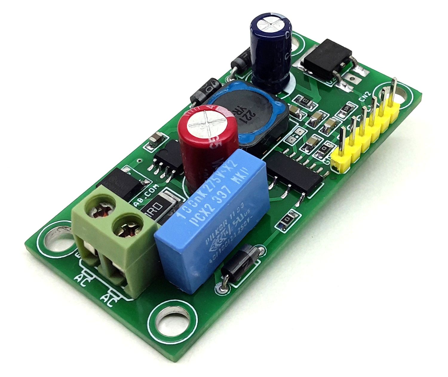
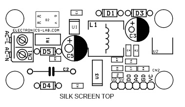



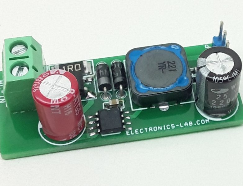
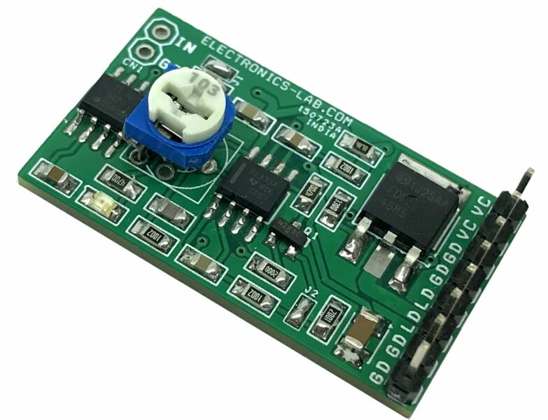
Hello,
The BOM and image are showing an L1 inductance of 68uH (Wurth 732-2995-1-ND) but the schema (and original sample circuit from Rhom) are showing an inductance of 100uH (Wurth 7447471221).
Could you please confirm the correct inductance value and ref ?
Thank you!
Thanks for noticing this issue. The correct Digikey number is 732-1696-1-ND and it’ fixed on the BOM above.
thank you!
Would you happen to have the centroid file (pick and place) ?
Thank you!
Let me check with our engineer and i will get back to you.
Hello,
Could you please confirm the orientation of D2 (how it should be soldered) ?
Hello,
I have another question about D2: the component orientation (AC side, + and – side) is OK, but which orientation should be followed to solder on board ?
Image: ZxWN3i0.png
Sorry for the bad English. To make it clear, the schema would need to be corrected for D2 (MDB10S) and use – and + instead of G and V. I assume D2 is the MDB10S as we see in the pictures right ?
C3 (565-3447-ND) does not fit the board… C3 is not blue
Can you please confirm which C3 part must be soldered ?
Photo: https://imgur.com/a/LMZatmq
Digikey Part #565-3447-ND is this: https://www.digikey.gr/en/products/detail/chemi-con/EGXL250ELL221MJC5S/3528652 and it is a generic 220uF/25V electrolytic capacitor with 10mm diameter. It seems like your capacitor is larger. Have you purchased it with this exact part no ?
The part from the BOM is:
UNITED CHEMIC EGXL250ELL221MJC5S
https://www.mouser.lu/ProductDetail/Chemi-Con/EGXL250ELL221MJC5S?qs=RpYEFuZ7GTgRgzzNqSkrqQ%3D%3D
I agree with you for the specs, they are the same, but the UNITED CHEMIC EGXL250ELL221MJC5S has a 5mm spacing which is wider than in the blue one seen in the photo.
C3 – blue in the photo – (565-3447-ND) has a diameter of 10mm according to Digikey specs
C5 – red in the photo – (732-8886-1-ND) has a diameter of 8mm according to Digikey specs
You can clearly see with the photo that the blue capacitor is smaller than the red one…
In the BOM, the reference for C3 is a 10mm diameter 5 mm spacing which is BIGGER than than C5 (red one).
So there is a mismatch between the photo and the BOM.
The lead spacing of the part is 5mm, but holes spacing designed as 3.86mm in Gerber file.
The problem is hole spacing too small designed in Gerber file.
So the lead spacing is bigger than hole spacing, that means the part can’t be soldered totally through the holes.
I decided to change for this one, which is the one used in the ROHM evaluation circuit for the BM1Z102FJ:
https://www.digikey.fr/en/products/detail/w%C3%BCrth-elektronik/860080474010/5727261
Wurth 860080474010
Capacitance
220 µF
Tolerance
±20%
Voltage – Rated
25 V
Ripple Current @ High Frequency
750 mA @ 100 kHz
Impedance
75 mOhms
Lead Spacing
0.138″ (3.50mm)
Size / Dimension
0.315″ Dia (8.00mm)
Mounting Type
Through Hole
We need to update the BOM with a 3.86mm lead spacing capacitor. I will add yours to the list. Thanks for noticing this.