AmpStrike – Battery Powered Bench Power Supply
- Jakub Felcenloben
- jakubf2007@gmail.com
- 28.211 Views
- advanced
- Non tested
Introduction
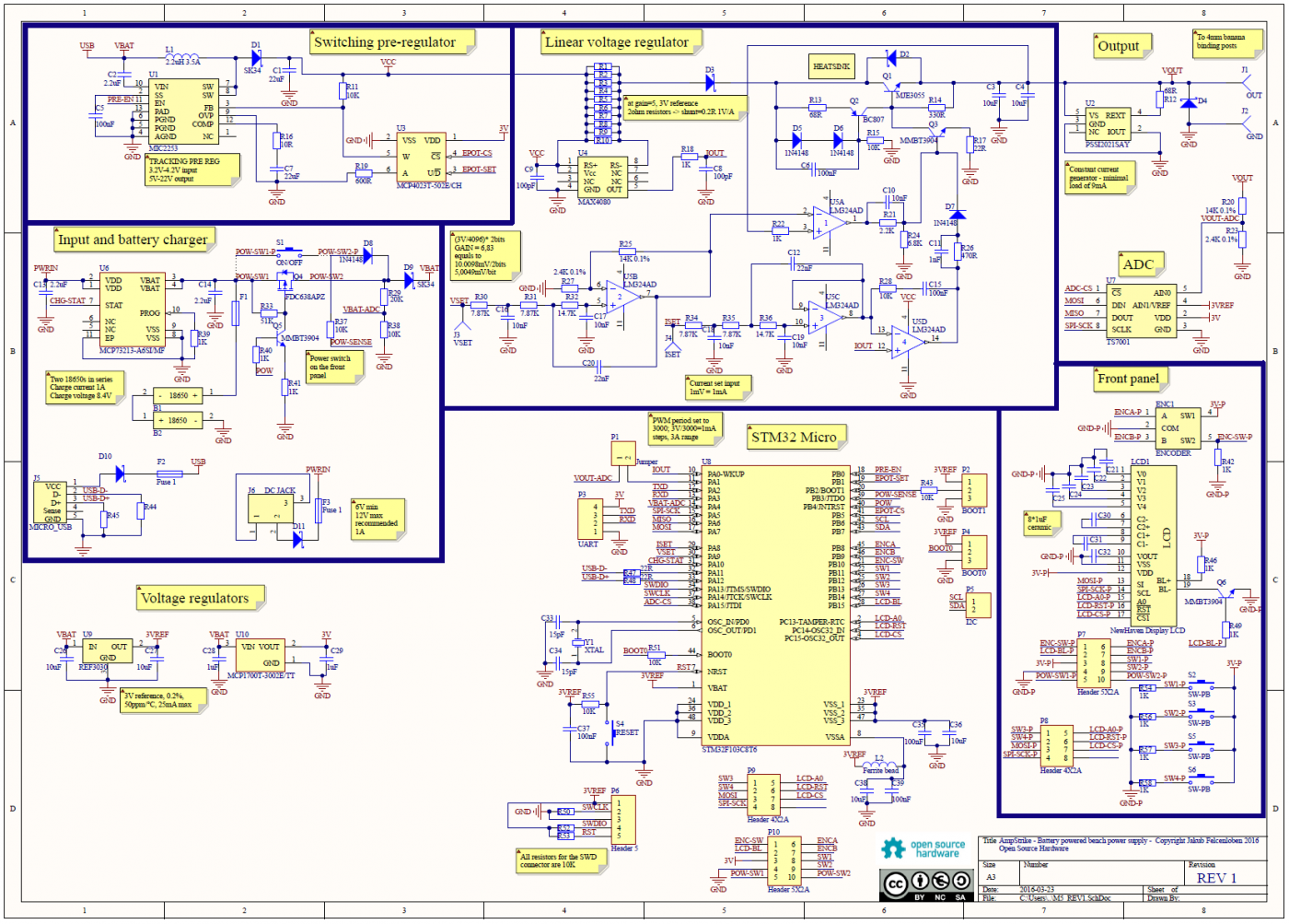
This is a small bench power supply that is powered by two lithium-ion batteries. The project was inspired by Dave Jones from EEVblog but the design is completely mine. The voltage range is 0-20V regulated in 10mV steps and maximum current is 1A with current limit set in 1mA steps.
Schematic
Linear Voltage Regulator
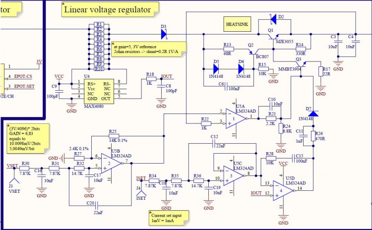
The power supply runs on a linear voltage regulator built on discrete components. The design of the linear regulator was inspired by the user Amspire from the EEVblog forum. The basic idea is that the Q1 pass transistor and U5A op amp act in a classic voltage regulating loop. U5A gets feedback from the output voltage and acts on Q1 in such a way that the output voltage equals the reference voltage on the inverting input. U5D acts as a comparator and switches the base of Q1 low to set the output voltage to 0V. It acts as a current limiter which is quickly switching on and off the output to maintain the set current limit. The current drawn by the load is measured by a MAX4080 current sense amplifier using a shunt resistor which is made up of 10 smaller resistors to get better power dissipation and current capability. U5B and U5C combined with the adjacent resistors and capacitors act as filters to smooth out the PWM signal from the microcontroller. The output contains two 10uF ceramic capacitors, a protecting diode and a small current source that acts as a small load to make the power supply more stable.
Microcontroller
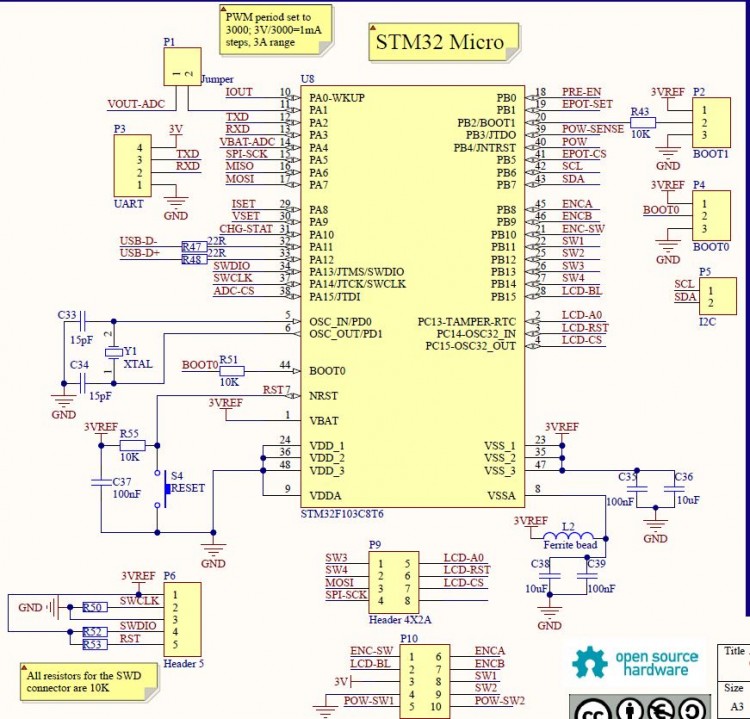
The entire voltage and current limit is controlled by a STM32F103 microcontroller. It might seem as a bit of an overkill for such a project, but actually these microcontrollers are quite cheap and they have the 12 bit PWM required for this project. The STM32 controls pretty much the entire power supply, including the switching pre-regulator, the output voltage and current limit and the front panel with an LCD, swtches and a rotary encoder used to set the desired values. Some USB capability can be added in the future. The user can also make use of the UART connector to plug in some bluetooth or Ethernet modules (with some additional code).
Pre-Regulator
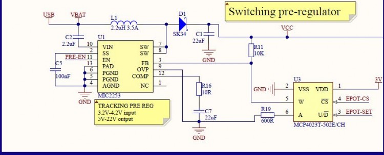
Since two batteries in series give only 8.4V maximum, the power supply needs a boost converter to get the 20V output, and it obviously has one. The MIC2253 with a couple of adjacent components provides the required voltage. The idea is that the DC-DC converter boosts the voltage and the linear regulator provides a smooth output. The bonus is, that with a small digital pot, the microcontroller can keep the input voltage just at the required level (about 2V above desired output) which minimises losses of energy from the battery and the heating of MTB3055 pass transistor.
The STM32 can even switch the pre-regulator off if required and just rely on the batteries powering the linear regulator directly.
You can find in the design two 3V rails. One, denoted on the schematic as 3VREF is a precise voltage reference for the microcontroller’s PWM and ADC, and also for the external ADC. The other is normal 3V line used to power the peripherals.
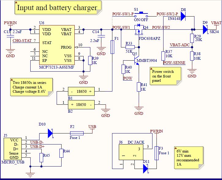
Input and Battery Charger
The batteries can be charged from DC input only, since the USB has too low a voltage to be able to charge batteries at 8.4V. However, when you plug the USB, the STM32 switches the batteries off and the entire power supply can be powered from USB (with power limited to 2.5W obviously). So in theory the AmpStrike can operate just on USB, without the batteries. The disadvantage of my design is that the USB is in no way isolated from the rest of the circuit. But provided that the microcontroller continously prevents the circuit from drawing more than 2.5W it shouldn’t be a huge problem especially since USB, DC input and batteries are all protected with resettable fuses.
The schematic also contains an external TS7001 12 bit ADC for measuring the output voltage, but I probably will end up measuring the output with the internal ADC in STM32. I am not sure yet, since I’m not really that familliar with the internal ADCs in these microcontrollers.
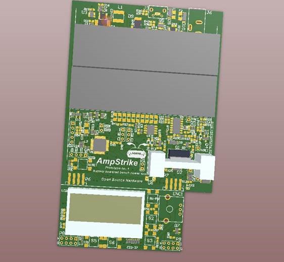
The PCB is designed with a front panel, which is v-scored to break it off and to mount it at a right angle on the main board. The power supply will be encased in a small aluminium enclousure.
I realise that the ideology and some parts are the same that Dave Jones used in his design, but I actually went through the entire design proccess myself and made decisions that made the most sense for me.
Note
The project is far from finished. Next step is making a prototype, trying to make the regulator stable and most importantly, writing the software. All sugestions are welcome, I’ll be sure to take them into consideration. I should also point out that I hope to be able to sell this power supply in the near future.




How is progress with this coming on?
Any rough idea of costs for the full BOM?
Are you aware of stm32duino.com – I’m sure they would be interested in this project.
Wa123sat@gmail.com
how open this project? i cant open it on altium 21 whith graber import