Arduino and BMP280 Based Weather Station
- Emmanuel Odunlade
- https://twitter.com/emmaodunlade
- emmaodunlade@gmail.com
- 9.364 Views
- moderate
- Tested
Weather stations are interesting projects for beginners and very useful for expert makers. They are usually quite simple to build but also provide fairly accurate and useful weather data. We have built a couple of them in different tutorials on this website, with the difference usually being, the combinations and sometimes the accuracy of the sensors used. For today’s tutorial, we will build another weather station, but this time, we will use the BMP280 sensor as the primary one and we will be able to monitor temperature, atmospheric pressure, and altitude.
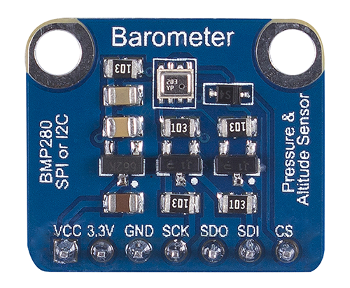
The BMP280 is the next-generation sensors from Bosch and it is an upgrade to their previous range of sensors including the BMP085, BMP180, and the BMP183. The BMP280 is great for all sorts of weather sensing with a low altitude noise of 0.25m and the same fast conversion rate as the previous sensors. In addition, the BMP280 can be used in both I2C and SPI mode and the sensor board version from Adafruit has a 3.3v voltage regulator and level shifter on board which means it can be used with either 3.3v or 5v voltage supply.
Along with the BMP280, we will use the I2C-based, 128×32 OLED from Adafruit to show the values obtained from the BMP280 sensor. At the end of today’s tutorial, you would know how to use the BMP280 or any other i2c device with the Arduino and also know how to display data on an OLED display using the Arduino.
Required Components
The following components are required to build this project;
- Arduino Uno
- Adafruit BMP280
- Adafruit OLED 128×32 I2C
- Breadboard
- Jumper Wire
The exact components used for this tutorial can be bought via the link attached to each of the components above.
Schematics
The schematic for this project is quite easy. The 128×32 OLED and the BMP280 both communicate with the Arduino via I2C, this means, they will be connected to the same pins (I2C) on the Arduino. Connect the components as shown in the schematics below.
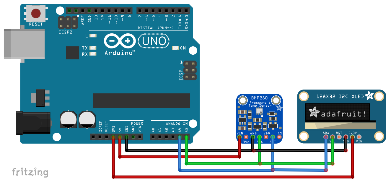
To make the connections easier to follow, here is a pin map showing how each of the components connects to the Arduino.
Arduino – BMP280
5V - vin
GND - GND
A4 - SDA
A5 - SCL
Arduino – OLED
3.3V - 3.3V
GND - GND
A4 - SDA
A5 - SCL
Go over the schematics once more to ensure everything is properly connected.
Code
To write the code for this project, we will use three key libraries; the Adafruit BMP280 library, the Adafruit GFX library and the Adafruit SSD1306 library. The three libraries can be downloaded via the Arduino Library Manager or via the download link attached to them.
The Adafruit BMP280 contains functions that make it easy to write the code that will obtain the parameters from the sensor while the Adafruit GFX and SSD1306 libraries are used to easily display texts and graphics on the OLED.
I will do a run through of the entire code and will try to explain as much as possible.
We start the code by including the libraries that we will use on the project after which we specify the dimensions (width = 128, height =32) of the OLED display and declare the pin of the Arduino to which the reset pin of the OLED is connected.
#include <Adafruit_GFX.h>
#include <Adafruit_SSD1306.h>
#include <Adafruit_BMP280.h>

#define SCREEN_WIDTH 128 // OLED display width, in pixels
#define SCREEN_HEIGHT 32 // OLED display height, in pixels
#define OLED_RESET    -1 // Reset pin # (or -1 if sharing Arduino reset pin)
Next, we create a class of the OLED library with the dimensions as arguments and also create a class of the BMP280 library.
Adafruit_SSD1306 display(SCREEN_WIDTH, SCREEN_HEIGHT, &Wire, OLED_RESET); //Declaring the display name (display)
Adafruit_BMP280 bmp;
Next, we write the void setup() function. We start by initializing the BMP using the bmp.begin() command and we also start communications with the OLED using the display.begin() function to get it started.
void setup() {
  bmp.begin();                                //Start the bmp
  display.begin(SSD1306_SWITCHCAPVCC, 0x3C); //Start the OLED display
With the initializations done, we set the color (using display.setTextColor function), set the font size (using the display.setTextSize() function), and display a welcome message (using the display.print() function). Feel free to change the displayed text as desired
display.clearDisplay();
  display.display();
  display.setTextColor(WHITE);
  display.setTextSize(1);
  display.print("SurtrTech");     //Show the name, you can remove it or replace it
  display.setCursor(32,12);
  display.setTextSize(2);
  display.println("BMP280");
  display.display();
  delay(2000);
}
With this done, we move to the void loop function(). We start by clearing the display (using the display.clearDisplay() function) after which we read the temperature, pressure and altitude, storing them into the variables T, P, and A respectively.
void loop() {

    display.clearDisplay();
    float T = bmp.readTemperature();           //Read temperature in C
    float P = bmp.readPressure()/100;         //Read Pressure in Pa and conversion to hPa
    float A = bmp.readAltitude(1019.66);      //Calculating the Altitude, the "1019.66" is the pressure in (hPa) at sea level at day in your region
Next, we display the measured parameters using the display.setCursor() function to effectively divide the OLED screen so they are all displayed at once. After this, we use the display.display() function to apply changes on the OLED. A time delay of 2000ms is set to ensure the values stay long enough on the display to be seen before they are replaced by new values.
display.setCursor(0,0);                   //Oled display, just playing with text size and cursor to get the display you want
    display.setTextColor(WHITE);
    display.setTextSize(2);
    display.print("Temp");

    display.setCursor(0,18);
    display.print(T,1);
    display.setCursor(50,17);
    display.setTextSize(1);
    display.print("C");

    display.setTextSize(1);
    display.setCursor(65,0);
    display.print("Pres");
    display.setCursor(65,10);
    display.print(P);
    display.setCursor(110,10);
    display.print("hPa");

    display.setCursor(65,25);
    display.print("Alt");
    display.setCursor(90,25);
    display.print(A,0);
    display.setCursor(110,25);
    display.print("m");

    display.display();
    delay(2000);
}
The complete code for the project is provided below and also attached under the download section of the tutorial.
#include <Adafruit_GFX.h>      //Libraries for the OLED and BMP280
#include <Adafruit_SSD1306.h>
#include <Adafruit_BMP280.h>

#define SCREEN_WIDTH 128 // OLED display width, in pixels
#define SCREEN_HEIGHT 32 // OLED display height, in pixels
#define OLED_RESET    -1 // Reset pin # (or -1 if sharing Arduino reset pin)

Adafruit_SSD1306 display(SCREEN_WIDTH, SCREEN_HEIGHT, &Wire, OLED_RESET); //Declaring the display name (display)
Adafruit_BMP280 bmp;

void setup() {
  bmp.begin();                                //Start the bmp
  display.begin(SSD1306_SWITCHCAPVCC, 0x3C); //Start the OLED display
  display.clearDisplay();
  display.display();
  display.setTextColor(WHITE);
  display.setTextSize(1);
  display.print("SurtrTech");     //Show the name, you can remove it or replace it
  display.setCursor(32,12);
  display.setTextSize(2);
  display.println("BMP280");
  display.display();
  delay(2000);
}

void loop() {

    display.clearDisplay();
    float T = bmp.readTemperature();           //Read temperature in C
    float P = bmp.readPressure()/100;         //Read Pressure in Pa and conversion to hPa
    float A = bmp.readAltitude(1019.66);      //Calculating the Altitude, the "1019.66" is the pressure in (hPa) at sea level at day in your region
                                              //If you don't know it just modify it until you get the altitude of your place

    display.setCursor(0,0);                   //Oled display, just playing with text size and cursor to get the display you want
    display.setTextColor(WHITE);
    display.setTextSize(2);
    display.print("Temp");

    display.setCursor(0,18);
    display.print(T,1);
    display.setCursor(50,17);
    display.setTextSize(1);
    display.print("C");

    display.setTextSize(1);
    display.setCursor(65,0);
    display.print("Pres");
    display.setCursor(65,10);
    display.print(P);
    display.setCursor(110,10);
    display.print("hPa");

    display.setCursor(65,25);
    display.print("Alt");
    display.setCursor(90,25);
    display.print(A,0);
    display.setCursor(110,25);
    display.print("m");

    display.display();
    delay(2000);
}
Demo
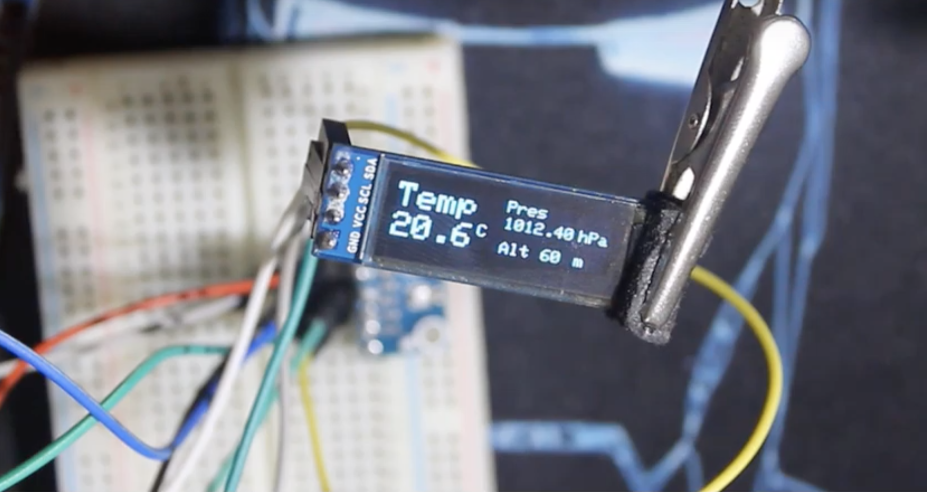
Go over the setup in the schematics to ensure you connected everything as described then upload the code to your Arduino. You should see the display come as shown in the image below after a while.
That’s all guys. Are you working on a quadcopter and want to add an additional sensor to determine altitude or you are just building a standard weather station and you need to add temperature and pressure, this might just be the sensor for you.
Feel free to reach out via the comment section if you have any difficulty getting things to work.
Till Next time.


Hi Michail, thank you for your quick response – much appreciated.
Firstly, I apologise for the (lengthy) query that follows but feel it necessary to clear out any ambiguity if/when using your Arduino project:
While I mentioned the “latest Bosch BME280” and you mention “The BMP280 is the next-generation sensors from Bosch”, according to Bosch this latest sensor is actually both in the one package; my Bosch sensor break-out board is actually labelled “BME/BMP280” but has only 4 pins as for I2C connectivity, even though the sensor itself has both SPI & I2C functionally.
Perhaps the situation with “BME & BMP duality” in this chip is what is causing the confusion here?
Your wiring schematic clearly shows I2C connection but noting your breakout board does have both SPI & I2C capability so presumably you are only referring to, and using the Adafruit BMP 280 board, which would explain why you are using Adafruit libraries etc., in your Arduino code?
If my presumption is correct, does it mean your Arduino code (using Adafruit libraries etc) is not compatible with the latest BME280 (I2C) breakout board?
Please refer to the link below and particularly the paragraphs immediately below your ‘VESI Training add’ in that link.
https://www.electronics-lab.com/project/arduino-bmp280-based-weather-station/
I look forward to your reply when convenient for you, please. Sincerely, Ian
Hello Ian, This was written a while back and while i can’t say for sure if it was before the launch of the BME series by BOSCH, a lot of things have definitely changed since then.
In terms of the library, Adafruit has a library specifically for the BME280. Looking at the examples, the changes involved may not be too difficult to try. Do check out the library and let me know if you need any other clarification. https://github.com/adafruit/Adafruit_BME280_Library
Hi Emmanuel, thanks for your feedback – much appreciated. Unfortunately, I have tried the Adafruit BME280 library and it is not compatible with the BME280 I2C (4 pin) breakout board as Adafruit makes its own breakout board which does utilize the same Bosch BME280 chip. – from memory I think it (Adafruit board) may only be BMP280 whereas my board is both (BME280 / BMP280. Such are the vagaries of micro-electronics and the many different manufacturers these days! Cheers and thanks again. Ian