Arduino FM Radio Receiver with TEA5767 and a Nokia 5110 LCD display
- Nick Koumaris
- https://educ8s.tv
- info@educ8s.tv
- 9.736 Views
- moderate
- Tested
FM radio transmitters and receivers are one of the projects that fascinated a lot of people and drove them to become makers. The lure of being able to deploy your own radio station, or build your own surveillance(-like) devices was what encouraged most of us to build our first fm transmitter or receiver. Nowadays, microcontrollers help simplify and add a lot of functions to analog projects that’s why for today’s tutorial, we will look on how you can build an Arduino based FM radio receiver using the TEA5767 FM radio and an Arduino Nano.
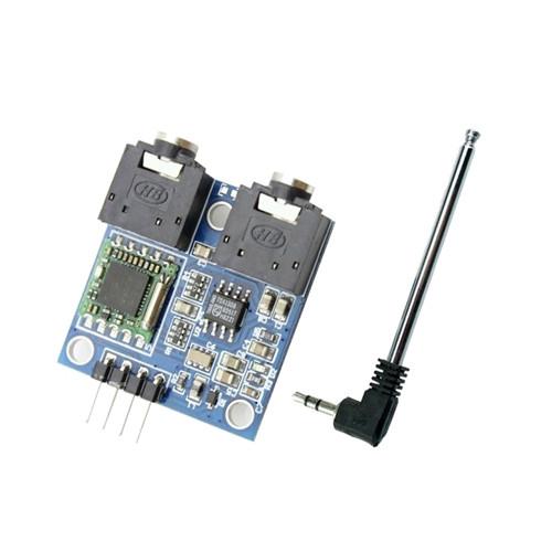
At the heart of today’s project is the cheap TEA5767 FM radio module. This module comes with all the components required to build a FM radio receiver, all on board. The module is based on the TEA5767GH which is a single-chip, electronically tuned, FM stereo radio for low-voltage applications with fully integrated Intermediate Frequency (IF) selectivity and demodulation. Through an I2C interface, the module can be connected to a microcontroller to digitally control its tuning frequency and other characteristics, giving room for opportunities to digitize some of its operations. It comprises of two headphone jacks, one of which is for connection to an headphone/speaker while the other is for connection to the antenna which usually comes with the module.
Some of the features of the TEA5767 chip are outlined below:
- High sensitivity due to integrated low-noise RF input amplifier
- FM mixer for conversion to IF of the US/Europe (87.5 MHz to 108 MHz) and Japanese (76 MHz to 91 MHz) FM band
- Preset tuning to receive Japanese TV audio up to 108 MHz
- RF Automatic Gain Control (AGC) circuit
- LC tuner oscillator operating with low cost fixed chip inductors
- FM IF selectivity performed internally
- No external discriminator needed due to fully integrated FM demodulator
- Crystal reference frequency oscillator; the oscillator operates with a 32.768 kHz clock crystal or with a 13 MHz crystal and with an externally applied 6.5 MHz reference frequency
- Phase-locked loop (PLL) synthesizer tuning system
- I 2C-bus and 3-wire bus, selectable via pin BUSMODE
- 7-bit IF counter output via the bus
- 4-bit level information output via the bus
- Soft mute(Can be switched off via Bus)
- Signal dependent mono to stereo blend
- Stereo Noise Cancelling (SNC)(Can be switched off via Bus)
- Signal dependent High Cut Control (HCC) (can be switched off Via Bus)
- Adjustment-free stereo decoder
- Autonomous search tuning function
- Standby mode
- Two software programmable ports
- Bus enable line to switch the bus input and output lines into 3-state mode
More info on the chip can be found in its datasheet.
For this project, we will connect the FM module to Arduino nano, so we will be able to set its tune frequency, display its signal strength, current frequency, stereo mode and other. The Nokia 5110 LCD will be used as the system’s display, providing visual feedback to the user while potentiometers are used to set the frequency and volume of the radio receiver. Turning the knobs in one direction will increase the volume or increase the frequency (depending on the particular knob being turned) and vice versa.
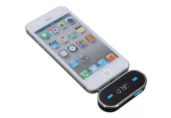
To test our radio receiver when the built is finished, we will use a small inexpensive FM radio transmitter (pictured above) which can be connected to our mobile phone to broadcast sound coming from it. Be sure to only use this within the limit defined for unlicensed broadcasting in your country, state or region.
Lets jump in
Required Components
We will need the following parts to build this project;
- Arduino Nano
- FM Radio Module
- Nokia 5110 LCD
- 10K Potentiometer
- Audio Amplifier
- 3W Speaker
- Large Breadboard
- Audio Cable
- Jumper Wires
- 3 in 1 wires
- FM Transmitter
- Power Bank
As usual, the exact model of these components that will be used for this tutorial can be bought via the links attached. The total cost of the project is around 15$ and could be lesser if you already have some of the components at home. The power bank is only used to make it easy to use the radio without being it tethered to a PC.
Schematics
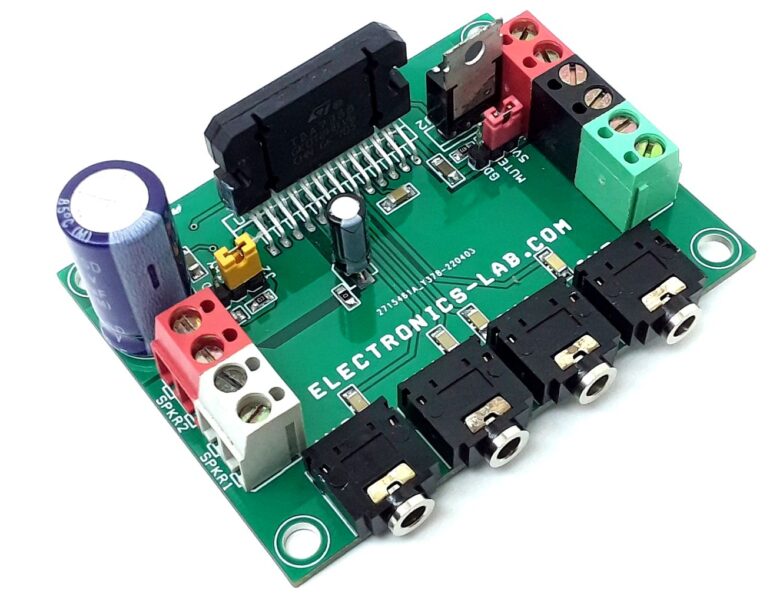
The schematics is a bit straight forward. The FM radio is connected to the Arduino via I2C while the Nokia 5110 is connected the same way as several of our past tutorials involving it. The only tricky part of the schematics is the connection of an external amplifier to the module. The inbuilt output amplifier for the module was designed to work with headphones, as such, the audio signal quality is poor when a speaker is connected to it. To amplify the sound, the module will be connected to an external amplifier.
Connect the components as shown in the schematics below;
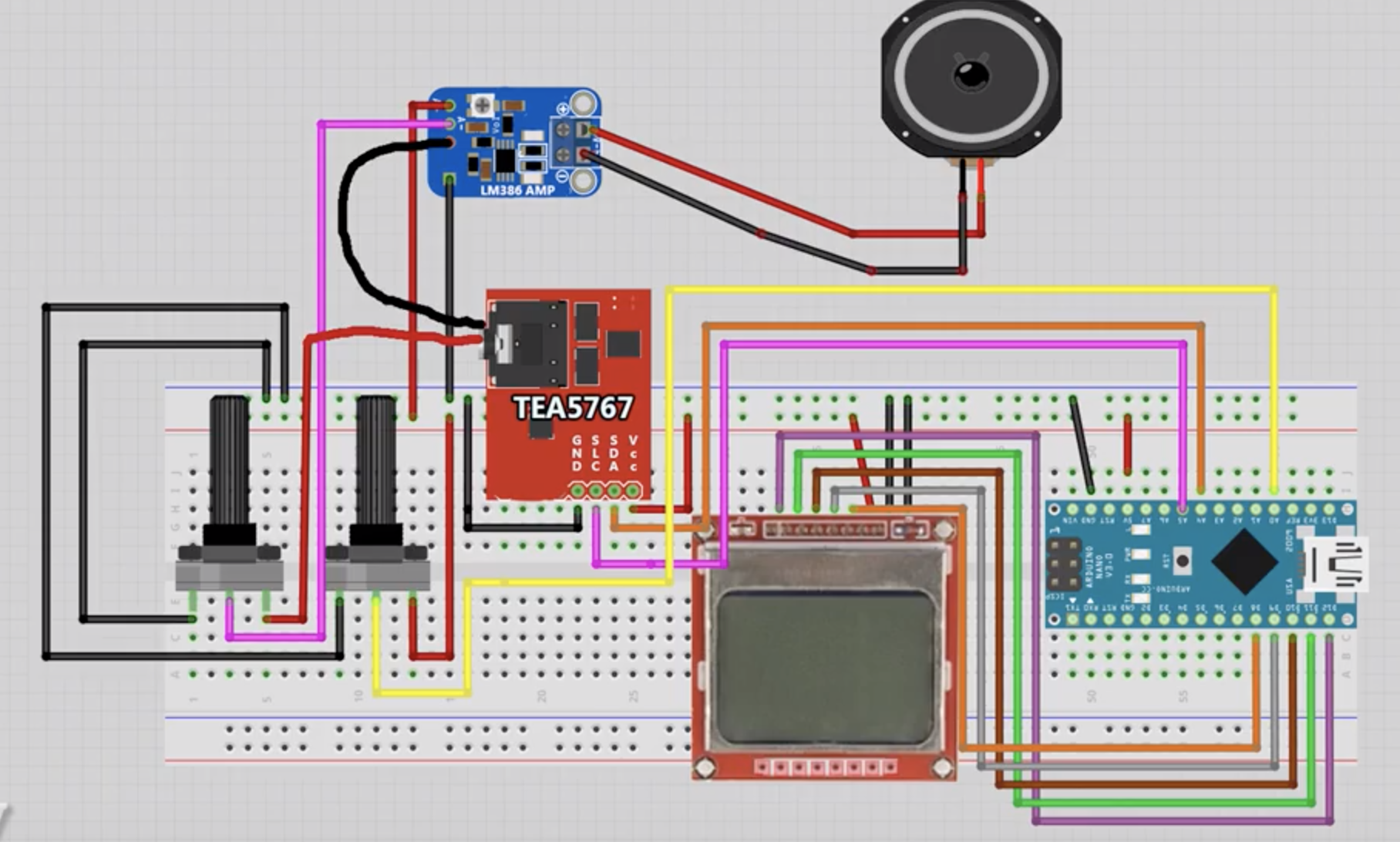
As usual, a pin to pin description of the connection between the components is shown below;
LCD – Arduino
Pin 1(RST) – D12
Pin 2(CE) – D11
Pin 3(DC) – D10
Pin 4(DIN) – D9
Pin 5(CLK) – D8
Pin 6(VCC) - VCC
Pin 7(LIGHT) - GND
Pin 8(GND) - GND
Arduino – TEA5767
5V - VCC
A5 - SCL
A4 - SDA
GND - GND
A lot was done using the Nokia 5110 LCD display in this tutorial, as such, it might be beneficial to check out some of our past tutorials, especially the tutorial on displaying custom graphics on the Nokia 5110 display.
Code
With the components all connected, we can now proceed to write the code for the project. The sketch for today’s project relies heavily on two libraries; the LCD5110_Graph library and the TEA5767N library. The LCD5110_graph library facilitates interaction with the Nokia5110 LCD display, making it easy to display graphics and text using functions, while the TEA5767, facilitates the interaction between the microcontroller and the FM Radio module.
To do a quick run through the code and provide an explanation to some of the concepts, we start the sketch as usual, by including the libraries that will be used for the project.
   /////////////////////////////////////////////////////////////////
   //                 Arduino FM Radio Project                    //
  //       Get the latest version of the code here:              //
 //     📥 http://educ8s.tv/arduino-fm-radio-project            //
/////////////////////////////////////////////////////////////////

#include <TEA5767N.h>  //https://github.com/mroger/TEA5767
#include <LCD5110_Graph.h> //http://www.rinkydinkelectronics.com/library.php?id=48
Next, we create an instance of the LCD graph library named LCD, with the pins of the Arduino to which the LCD is connected as arguments. We also create an instance of the TEA5767 library named radio.
LCD5110 lcd(8,9,10,12,11);
TEA5767N radio = TEA5767N();
Next, we create variables to hold the fonts that we will use on the LCD and also create variables to hold the icons that we will use to show the volume level. The byte array to hold all of these icons is going to be placed in the same folder as the code for the project so they can be easily referenced.
extern unsigned char BigNumbers[];
extern unsigned char TinyFont[];

extern uint8_t splash[];
extern uint8_t signal5[];
extern uint8_t signal4[];
extern uint8_t signal3[];
extern uint8_t signal2[];
extern uint8_t signal1[];
Next, we declare the analog pin to which the potentiometer that controls the frequency is connected and also create variable names to hold the values of the raw value of frequency (int), current frequency, previous frequency alongside a variable to store the signal strength of the FM signal.
int analogPin = 0;
int val = 0;
int frequencyInt = 0;
float frequency = 0;
float previousFrequency = 0;
int signalStrength = 0;
With this done, we proceed to write the void setup() function. We start the function by initializing the radio module, setting the mono reception and instructing it to cancel stereo noise. Next, we initialize the display using the initScreen() function and display the splash screen. The splash screen for this project was developed using photoshop and converted to a byte array using bitmap converter. You can check out one of our past tutorials on displaying custom graphics with the Nokia 5110 display to better understand how that works.
void setup()
{
  radio.setMonoReception();
  radio.setStereoNoiseCancellingOn();
  initScreen();
  showSplashScreen();
  Serial.begin(9600);
}
Next, is the void loop() function. We read the values from the potentiometer that controls the frequency every few milliseconds and map it to our frequency value.
for(int i;i<30;i++)
{
   val = val + analogRead(analogPin);
   delay(1);
}

val = val/30;
frequencyInt = map(val, 2, 1014, 8700, 10700); //Analog value to frequency from 87.0 MHz to 107.00 MHz
float frequency = frequencyInt/100.0f;
To prevent noise and achieve a stable tune, we only change the frequency of the radio module when there is a considerable change between the last frequency and the current value set by the potentiometer. If a significant difference exists, we then use the radio.selectFrequency() function to tune the radio to that frequency. After this, we obtain the signal strength at that frequency and display it on the LCD using the PrintSignalStrength() function, followed by the display of the stereo state and the display of the frequency on the LCD. The current frequency is then mapped to the previous frequency, awaiting the next time, the frequency is changed.
if(frequency - previousFrequency >= 0.1f || previousFrequency - frequency >= 0.1f)
  {
    lcd.clrScr();
    radio.selectFrequency(frequency);
    printSignalStrength();
    printStereo();
    printFrequency(frequency);
    previousFrequency = frequency;
  }
In case there is no significant change in frequency, the last frequency is retained and displayed along with the signal strength and the stereo.
 lcd.clrScr();
  printSignalStrength();
  printStereo();
  printFrequency(frequency);
  delay(50);
  val = 0;
}
The complete code for the project is available below and also attached under the download section
    /////////////////////////////////////////////////////////////////
   //                 Arduino FM Radio Project                    //
  //       Get the latest version of the code here:              //
 //     📥 http://educ8s.tv/arduino-fm-radio-project            //
/////////////////////////////////////////////////////////////////

#include <TEA5767N.h>  //https://github.com/mroger/TEA5767
#include <LCD5110_Graph.h> //http://www.rinkydinkelectronics.com/library.php?id=48

LCD5110 lcd(8,9,10,12,11);
TEA5767N radio = TEA5767N();

extern unsigned char BigNumbers[];
extern unsigned char TinyFont[];

extern uint8_t splash[];
extern uint8_t signal5[];
extern uint8_t signal4[];
extern uint8_t signal3[];
extern uint8_t signal2[];
extern uint8_t signal1[];

int analogPin = 0;
int val = 0;
int frequencyInt = 0;
float frequency = 0;
float previousFrequency = 0;
int signalStrength = 0;

void setup()
{
  radio.setMonoReception();
  radio.setStereoNoiseCancellingOn();
  initScreen();
  showSplashScreen();
  Serial.begin(9600);
}

void loop() {

  for(int i;i<30;i++)
  {
     val = val + analogRead(analogPin);
     delay(1);
  }

  val = val/30;
  frequencyInt = map(val, 2, 1014, 8700, 10700); //Analog value to frequency from 87.0 MHz to 107.00 MHz
  float frequency = frequencyInt/100.0f;

  if(frequency - previousFrequency >= 0.1f || previousFrequency - frequency >= 0.1f)
  {
    lcd.clrScr();
    radio.selectFrequency(frequency);
    printSignalStrength();
    printStereo();
    printFrequency(frequency);
    previousFrequency = frequency;
  }

  lcd.clrScr();
  printSignalStrength();
  printStereo();
  printFrequency(frequency);
  delay(50);
  val = 0;
}

void initScreen()
{
  lcd.InitLCD();
  lcd.setFont(BigNumbers);
  lcd.clrScr();
}

void showSplashScreen()
{
  lcd.drawBitmap(0, 0, splash, 84, 48);
  lcd.update();
  delay(3000);
  lcd.clrScr();
  lcd.update();
}

void printFrequency(float frequency)
{
  String frequencyString = String(frequency,1);
  if(frequencyString.length() == 4)
  {
    lcd.setFont(BigNumbers);
    lcd.print(frequencyString,14,12);
    lcd.update();
  }
  else
  {
    lcd.setFont(BigNumbers);
    lcd.print(frequencyString,0,12);
    lcd.update();
  }
}
void printStereo()
{
    boolean isStereo = radio.isStereo();
     if(isStereo)
    {
      lcd.setFont(TinyFont);
      lcd.print("STEREO",55,2);
    }
}

void printSignalStrength()
{
  signalStrength = radio.getSignalLevel();
  String signalStrenthString = String(signalStrength);
  if(signalStrength >=15)
  {
    lcd.drawBitmap(1, 1, signal5, 17 , 6);
  }else if(signalStrength >=11 && signalStrength <15)
  {
    lcd.drawBitmap(1, 1, signal4, 17 , 6);
  }
  else if(signalStrength >=9 && signalStrength <11)
  {
    lcd.drawBitmap(1, 1, signal3, 17 , 6);
  }
   else if(signalStrength >=7 && signalStrength <9)
  {
    lcd.drawBitmap(1, 1, signal2, 17 , 6);
  }
   else if(signalStrength <7)
  {
    lcd.drawBitmap(1, 1, signal1, 17 , 6);
  }
}
Demo
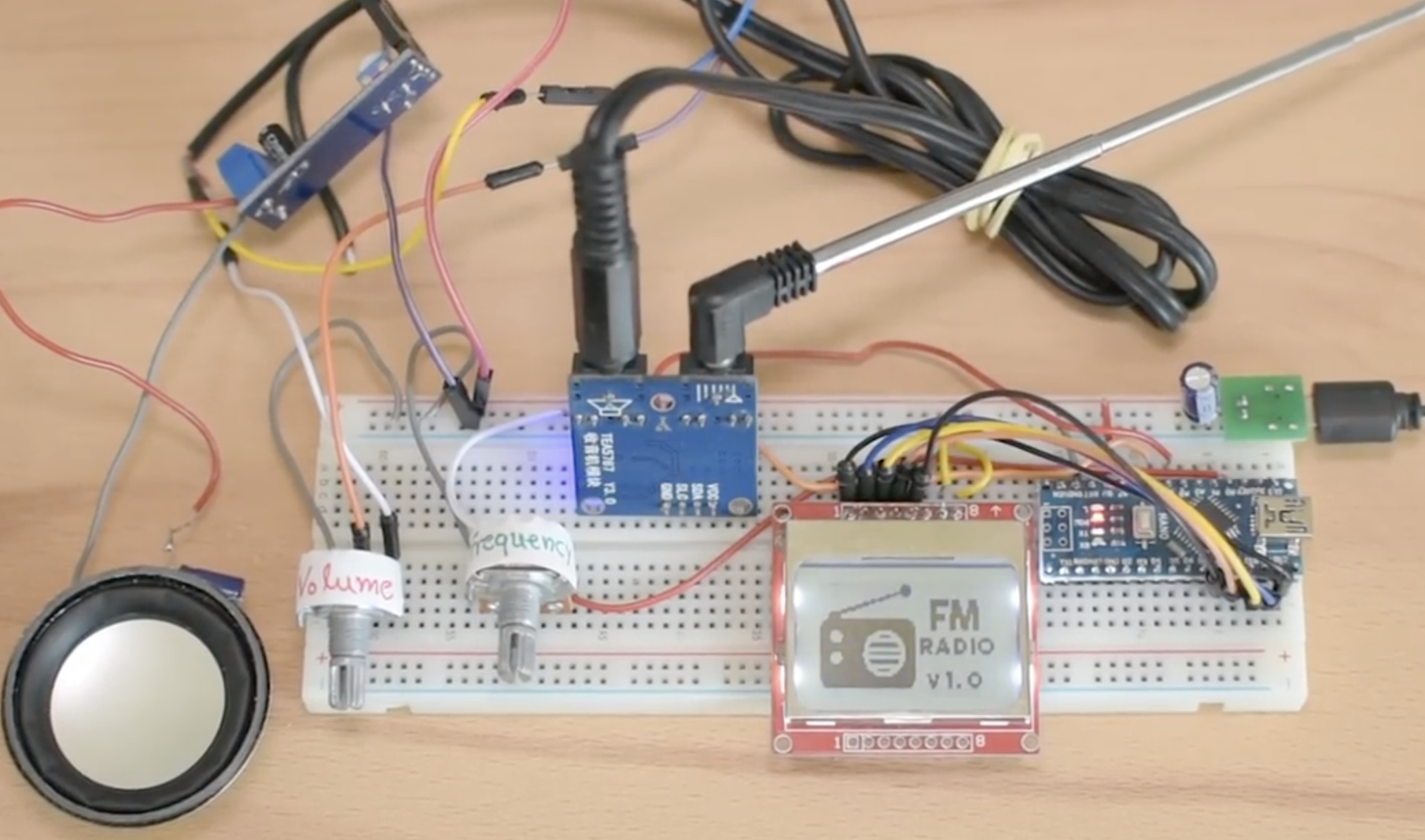
Go over the connections once again to ensure everything is as it should be, especially the connection between the external amplifier and the speaker. With that done, connect the Arduino to your computer and upload the code. Ensure all the libraries have been installed to prevent errors. With the code upload successful, after a couple of seconds, you should see the splash screen come up as shown in the image below.
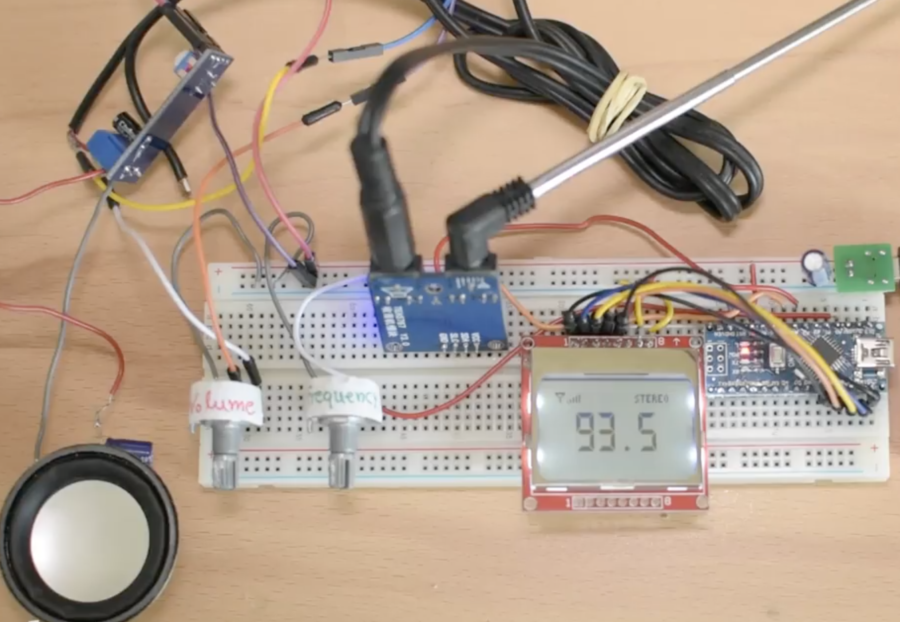
This will then be followed by the main window which displays the current frequency to which the radio is tuned.
Turn up the volume and tune the radio to any of your local stations, you should now be able to hear the radio. Another way to test your receiver is to use an inexpensive radio transmitter which can be connected to your mobile phone and tune the radio to its frequency. However, be sure to ensure you are within the provisions of the law of where you are, this last approach may be classified as unlicensed broadcasting in some places.
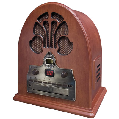
That’s it for this tutorial guys; your own personal FM Radio Receiver. While this system is characterized by the poor audio output, with the use of a better amplifier to improve the sound, and a 3D printed or CNC machined enclosure, it could be transformed into a fantastic retro styled FM radio like the one in the image below. Feel free to reach me via the comment section for answers to any question you might have about this project. Look forward to seeing your Retro FM radios.
The video version of this tutorial is available on youtube.




Any tips for automatically switching off the amp when the headphones are connected?
There is no initializatoin of i at line 41. It should be: for(int i=0;i<30;i++)
if used without the initialization the loop would not be executed, and the pot value would not be red. then the frequency would not change, abd stand for 87 only.