3.3V Automotive Step-Down Regulator – Low-Iq, Dual-Mode
- Rajkumar Sharma
- 45 Views
- easy
- Tested
- SKU: EL154214
- Quote Now
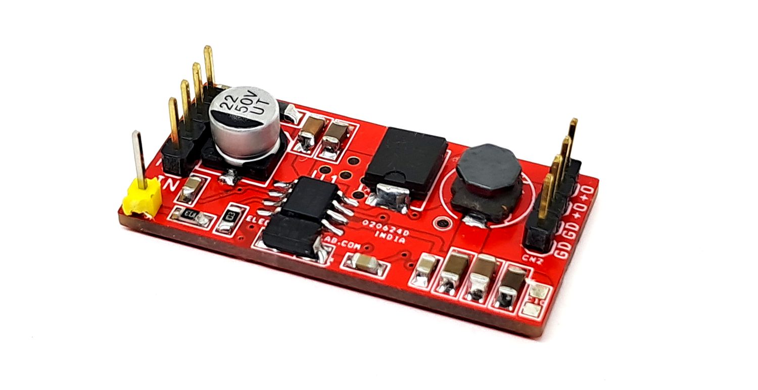
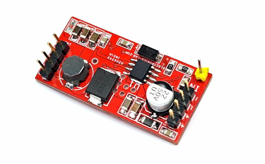
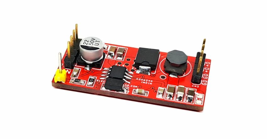
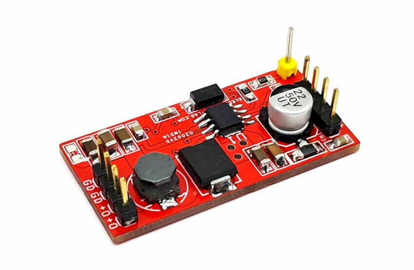
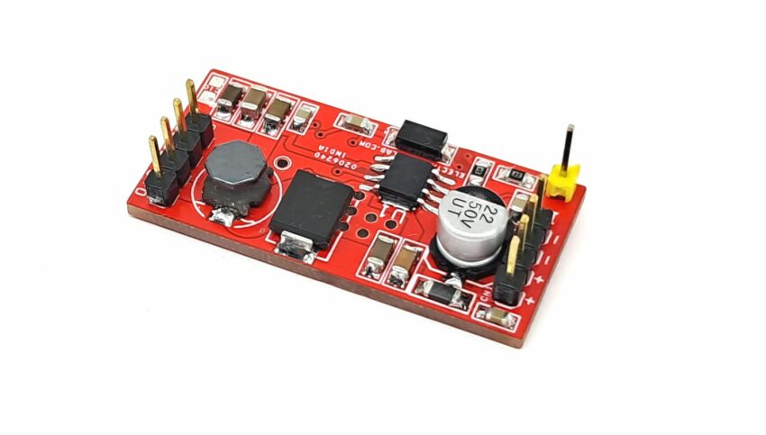
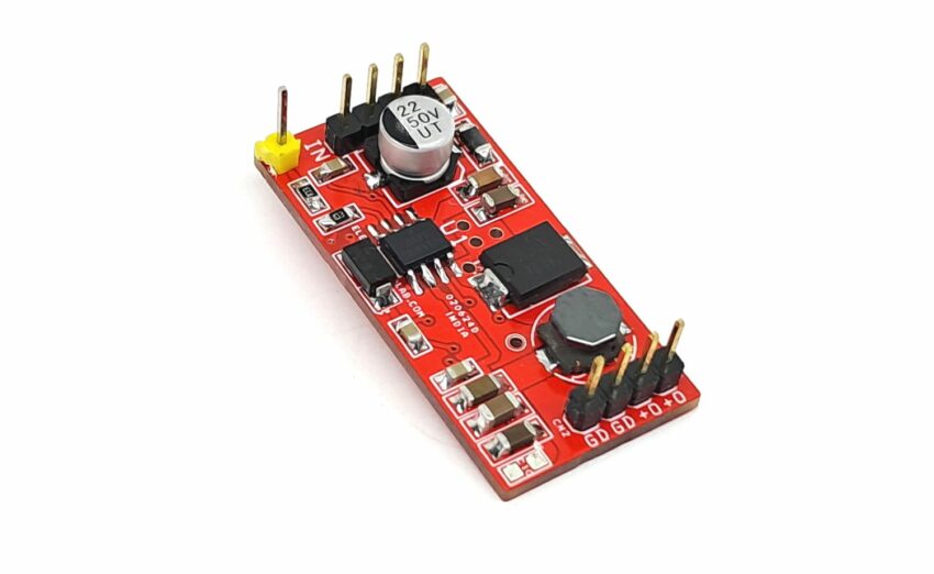
This is a Dual Mode regulator intended for Automotive, battery-connected applications that operate with up to a 36V input supply. Depending on the output load, it operates either as a PWM Buck Converter or as a Low Drop-Out Linear Regulator, and is suitable for systems with low noise and Low Quiescent Current requirements often encountered in automotive driver information systems. The project consists of NCV891330 chip which provides several protection features expected in automotive power supply systems such as current limit, short circuit protection, and thermal shutdown. In addition, the high switching frequency produces low output voltage ripple. Operating power supply range 3.7V to 36V. Output voltage 3.3V load current up to 3A. Operating frequency 2MHz.
Features
- VIN operating range 3.7 V to 36 V
- 3.0 A maximum output current in PWM mode
- Logic level Enable pin can be tied to the battery
- Fixed Output Voltage of 3.3 V
- 2 MHz Free-running Switching Frequency
- Header Connectors for Supply Input and Output
- Header Connector for Enable ( Tie Enable to VIN)
- +/-2 % Output Voltage Accuracy
- 30 µA Iq in Light Load Condition
- PCB Dimensions 39.37 x 19.05 mm
Hybrid Low−Power Mode
A high−frequency switch−mode regulator is not very efficient in light load conditions, making it difficult to achieve low−Iq requirements for sleep−mode operation. To remedy this, the NCV891330 includes a low−Iq linear regulator that turns on at light load, while the PWM regulator turns off, ensuring a high−efficiency low−power operation. Another advantage of linear mode is the tight regulation free of voltage ripple usually associated with low−Iq switchers in light load conditions. At initial start−up the NCV891330 always runs in PWM converter mode, regardless of the output current, and goes through a soft start. It then stays in PWM mode if the output current is high enough. If the output current is low, the NCV891330 transitions to Linear Regulator mode, after a 300 s period during which it assesses the level of output current. Note that the Reset signal needs to be high before the IC starts to look at the output current level. It stays in this low−power mode until the output current exceeds the ILIN (lim) limit: it then transitions to PWM converter mode. This transition happens in less than 2 s, so that the transient response is not affected by the mode change. Once the NCV891330 has transitioned to switcher mode, it cannot go back to low−Iq mode before a 500 s blanking period has elapsed, after which it starts looking at the output current level. If the NCV891330 is in low−Iq Linear Regulator mode in normal battery range, it will transition to switcher mode when VIN increases above V LIN to SW(HV), regardless of the output current. Similarly, if the NCV891330 is in PWM mode and VIN is higher than VFLDUP, it will not transition to low−Iq Linear mode even if the output current becomes lower than IN to L. At low input voltage, the NCV891330 stays in low−Iq mode down to V LIN to SW(LV) if it entered this mode while in normal battery range. However, it may not enter low−Iq mode below 8 V depending on the charge of the bootstrap capacitor (see Bootstrap section and typical characteristics curves for details)
Input Voltage
An Undervoltage Lockout (UVLO) circuit monitors the input. The circuit can inhibit switching and reset the Soft−start circuit if there is insufficient voltage for proper regulation. Depending on the output conditions (voltage option and loading), the NCV891330 may lose regulation and run-in drop−out mode before reaching the UVLO threshold
Soft−Start
Upon being enabled or released from a fault condition, and after the DRV voltage is established, a soft−start circuit ramps the switching regulator error amplifier reference voltage to the final value. During soft−start, the average switching frequency is lower until the output voltage approaches regulation.
Current Limiting
Due to the ripple on the inductor current, the average output current of a buck converter is lower than the peak current setpoint of the regulator.
Short Circuit Protection
During severe output overloads or short circuits, the NCV891330 automatically reduces its switching frequency. This creates duty cycles small enough to limit the peak current in the power components, while maintaining the ability to automatically re-establish the output voltage if the overload is removed. In more severe short−circuit conditions where the inductor current is still too high after the switching frequency has fully folded back, the regulator enters a hiccup mode that further reduces the power dissipation and protects the system.
Thermal Shutdown
A thermal shutdown circuit inhibits switching, resets the Soft−start circuit, and removes DRV voltage if internal temperature exceeds a safe level. Switching is automatically restored when temperature returns to a safe level
Connections
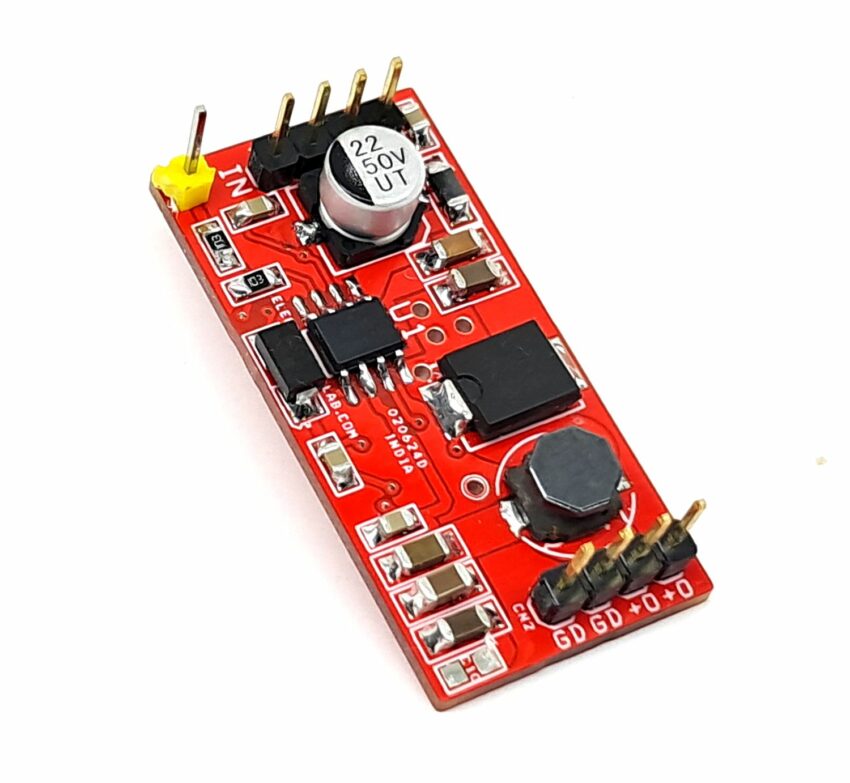
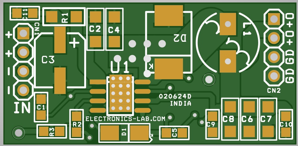
- CN1: Pin 1,2=3.7V to 36V DC, Pin 3,4=GND
- CN2: Pin 1,2=+3.3V Output, Pin 3,4=GND
- CN: Enable (Connect it to Vin 3.7V To 36V)
Schematic
Parts List
| NO. | QNTY. | REF. | DESC. | MANUFACTURER | SUPPLIER | SUPPLIER PART NO |
|---|---|---|---|---|---|---|
| 1 | 2 | CN1,CN2 | 4 PIN MALE HEADER PITCH 2.54MM | WURTH | DIGIKEY | 732-5317-ND |
| 2 | 3 | C1,C5,C9 | 100nF/50V CERAMIC SMD SIZE 0805 | YAGEO/MURATA | DIGIKEY | |
| 3 | 2 | C2,C4 | 10uF/50V CERAMIC X7R SMD SIZE 1206 | YAGEO/MURATA | DIGIKEY | |
| 4 | 1 | C3 | 22uF/50V ELEKCTROLYTIC | NICHICON | DIGIKEY | 493-6180-1-ND |
| 5 | 1 | C6 | 22uF/10V CERMAIC SMD X7R 1206 | YAGEO/MURATA | DIGIKEY | |
| 6 | 2 | C7,C8 | 10uF/10V CERAMIC X7R SMD SIZE 1206 | YAGEO/MURATA | DIGIKEY | |
| 7 | 1 | C10 | DNP | |||
| 8 | 1 | C11 | 1uF/50V CERAMIC SMD SIZE 0805 | YAGEO/MURATA | DIGIKEY | |
| 9 | 1 | D1 | ES1B SMD DIODE FAST SWITCHING | YAGEO | DIGIKEY | 13-ES1BCT-ND |
| 10 | 1 | D2 | MBRS360 FAST SWITCHING DIODE | ONSEMI | DIGIKEY | MBRS360T3GOSCT-ND |
| 11 | 1 | L1 | 2.2uH/6A 8MM RELAY | WURTH | DIGIKEY | 732-3759-ND |
| 12 | 1 | R1 | 0E SMD SIZE 1206 | YAGEO/MURATA | DIGIKEY | |
| 13 | 2 | R2,R3 | 10K 5% SMD SIZE 0805 | YAGEO/MURATA | DIGIKEY | |
| 14 | 1 | U1 | NCV891330PD33R2G | ONSEMI | DIGIKEY | 488-NCV891330PD33R2GCT-ND |
Connections


