BLDC Motor and DC Brushed Motor Driver
- Rajkumar Sharma
- 1.212 Views
- medium
- Tested
- SKU: EL117874
- Quote Now
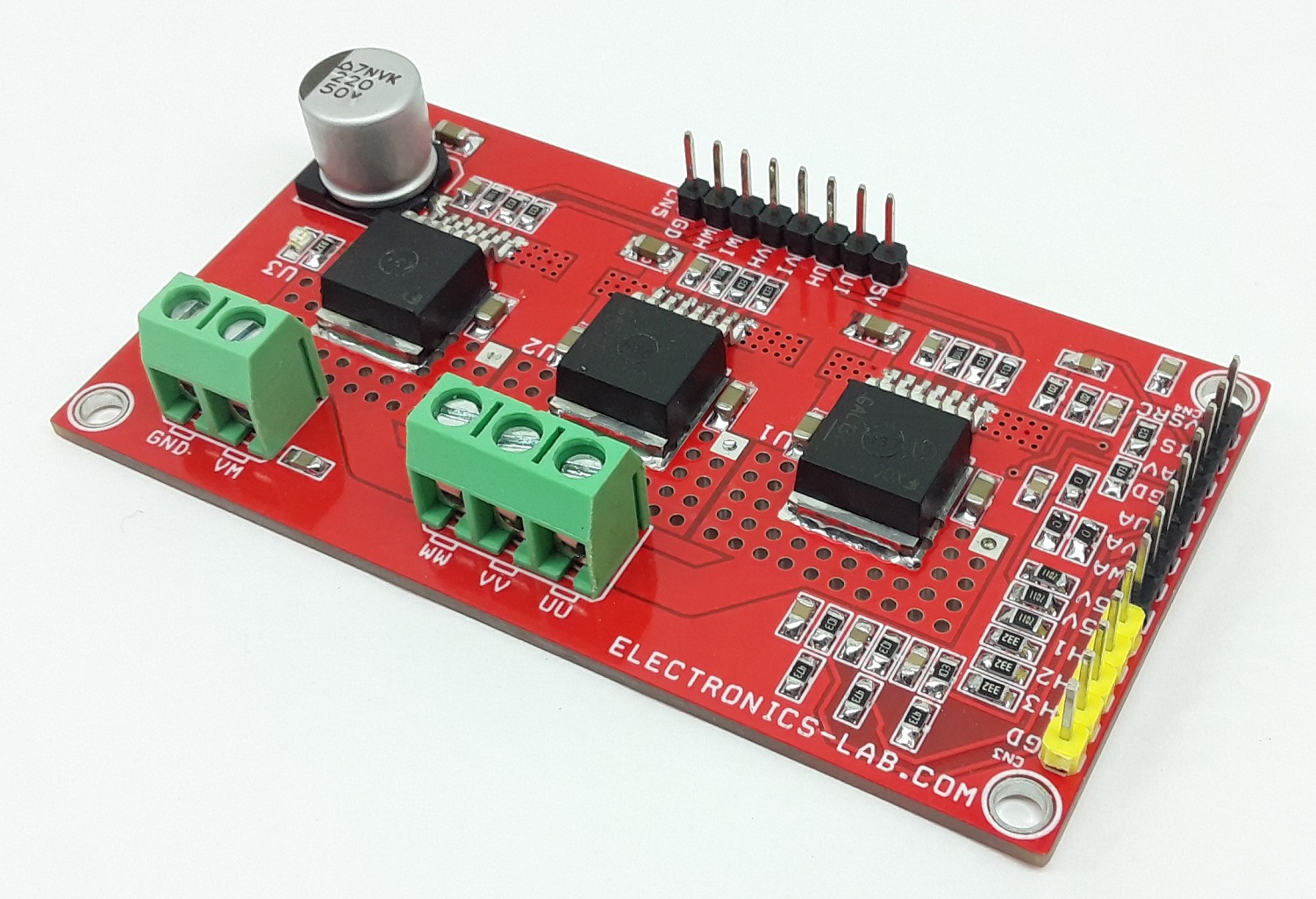
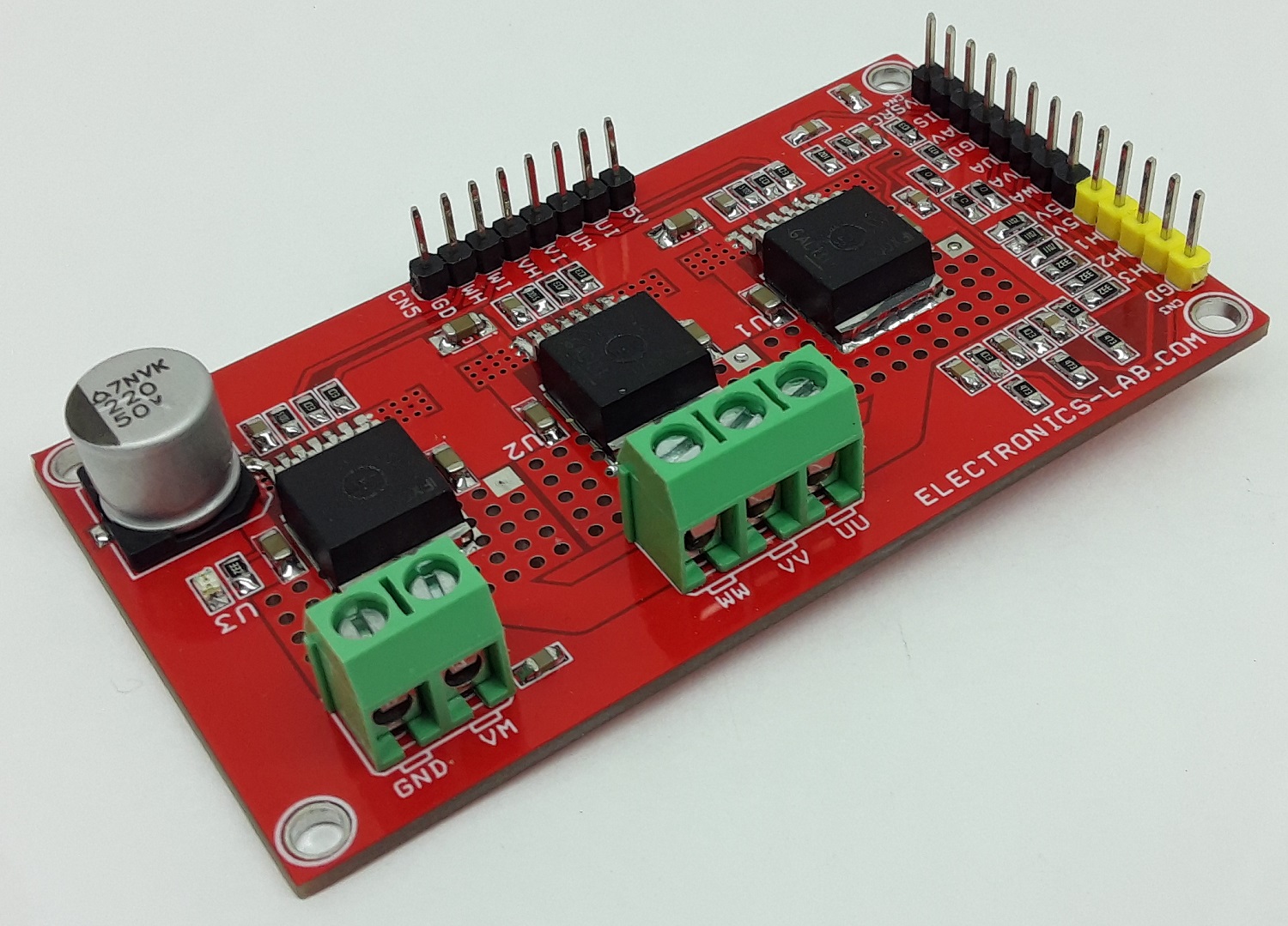
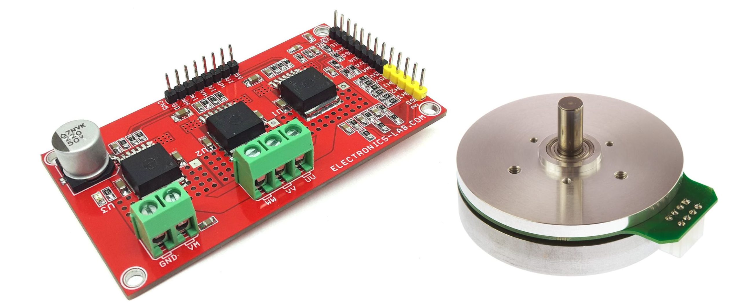
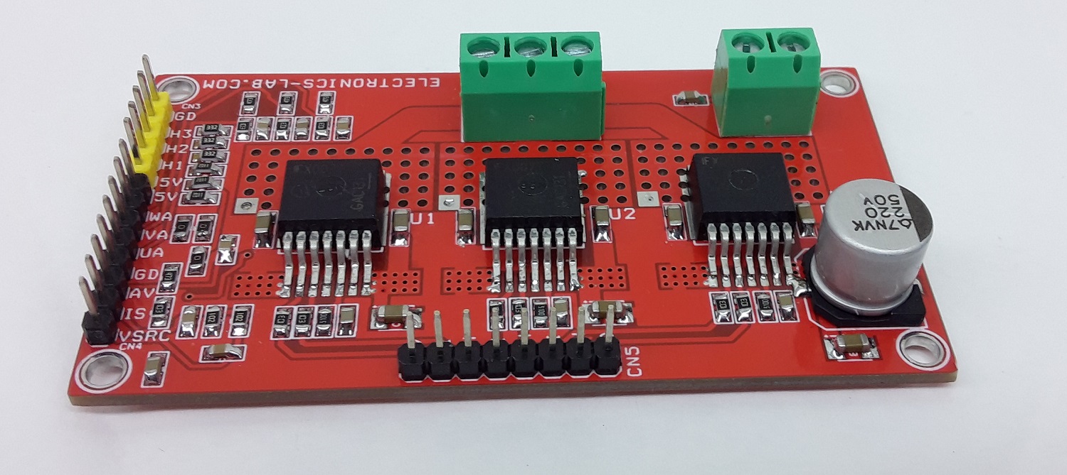
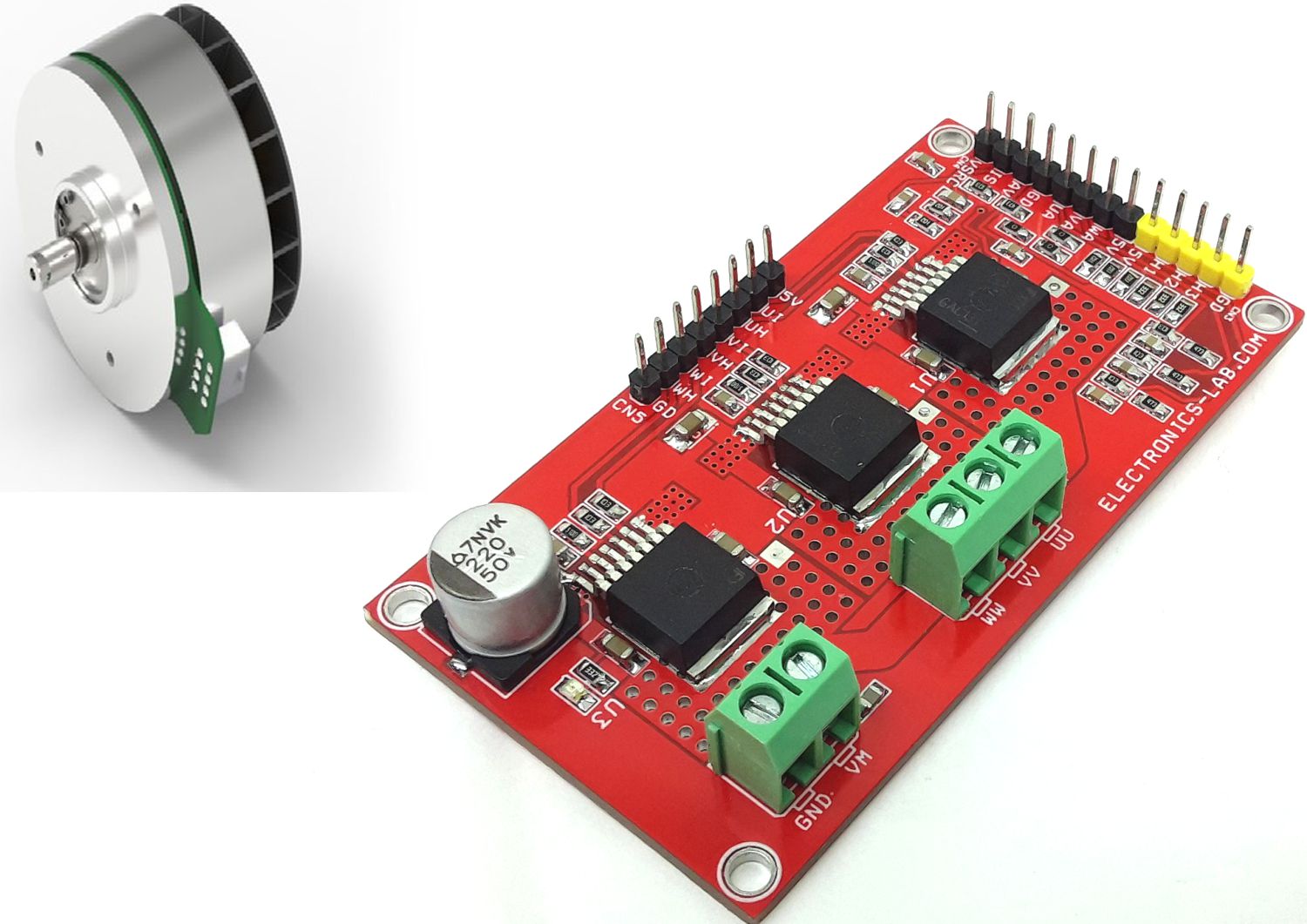
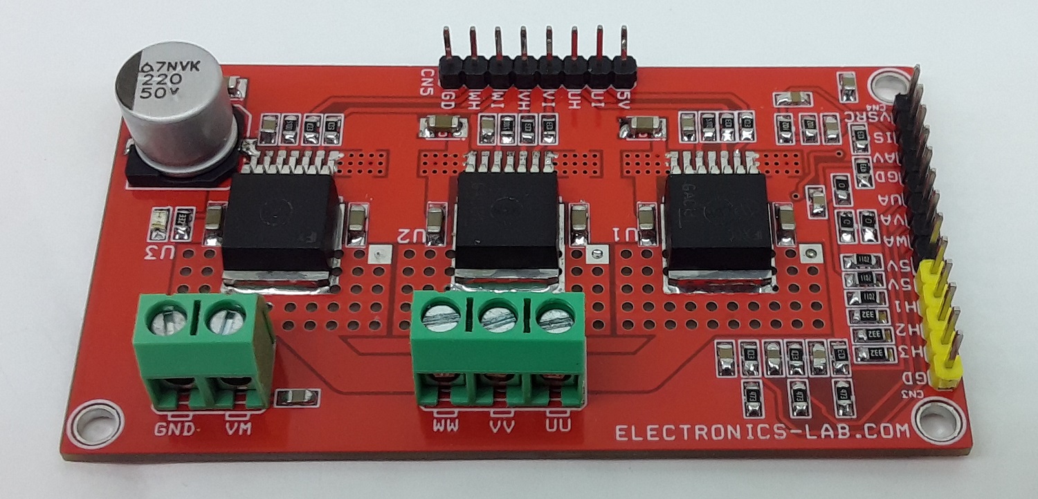
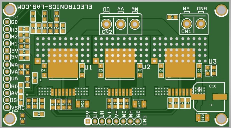
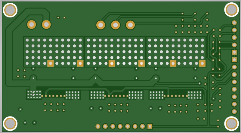
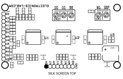
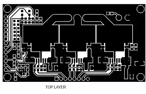
This BLDC motor driver board is equipped with a smart IFX007T half-bridge. The BLDC motor control project is capable to drive one BLDC motor. Alternatively, it can be used to drive one or two bi-directional DC motors (H-Bridge configuration, cascaded to support the second motor) or up to three uni-directional DC motors (half-bridge configuration). The implemented integrated IFX007T half-bridges can be controlled by a PWM via the IN Pin. Interfacing to a microcontroller or Arduino is easy by the integrated driver IC which features logic level inputs, diagnosis with current sense, slew rate adjustment, and dead time generation, etc. The three IFX007T half-bridges are also fully protected against over-temperature, under-voltage, overcurrent, and short circuit events. The project is capable of high-frequency PWM e.g., 30Khz. All inputs are logic level, current sense outputs are for diagnosis purposes, and slew rates are adjustable using R7, R8, R9. This is able to be used for fast and inexpensive prototyping of (BL)DC motor control, easy testing of half-and full-bridge motor control Status flag diagnosis with current sense capability, Over-temperature shut down with latch behavior and under-voltage shut down. It is advisable to use forced cool air to control the temperature of the IFX007 chip.
Arduino Code
Arduino Code is provided to test the board. The user will be able to drive a single brushed DC motor with speed control function.
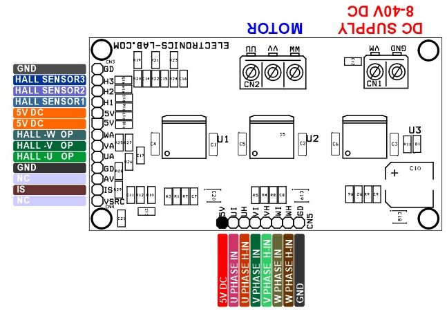
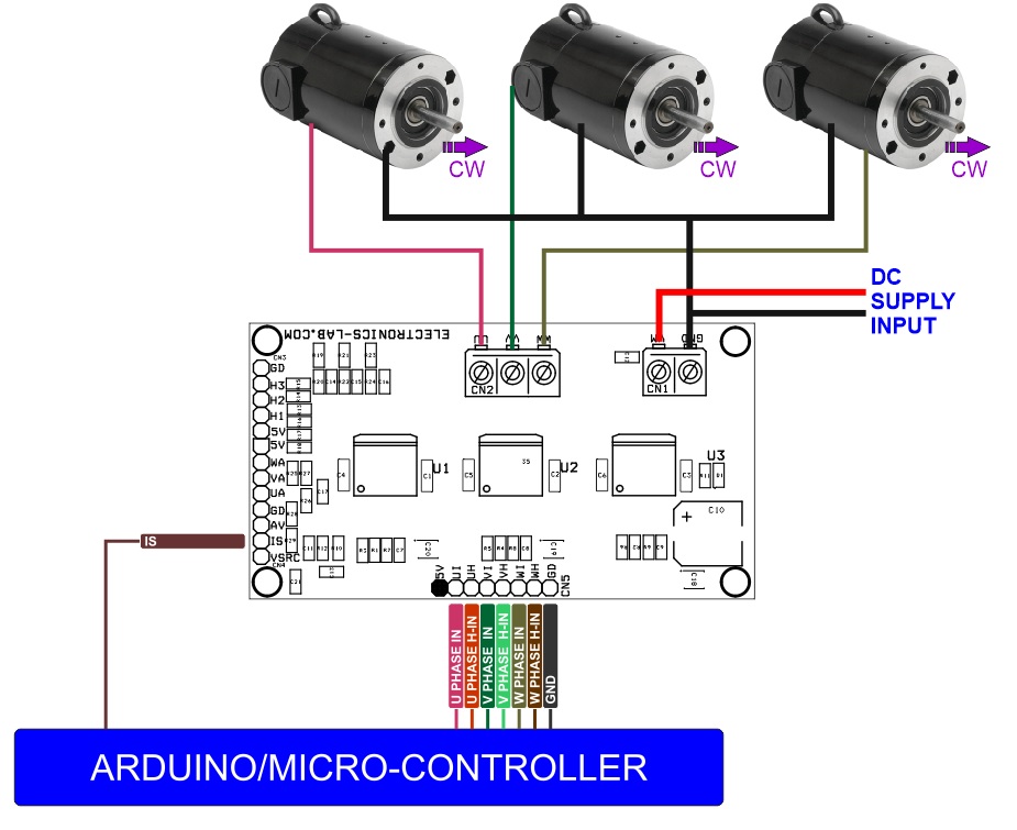
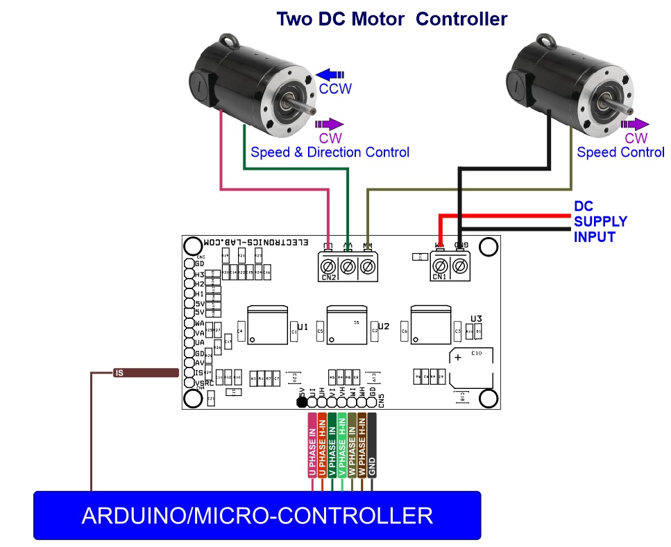
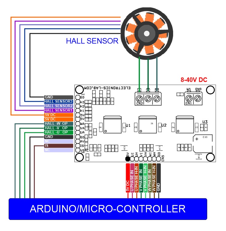
- Connections: Arduino Digital Pin D5 = VH Pin 5 of Connector CN5, Arduino Digital Pin D10 = VI Pin 4 of Connector CN5, Arduino GND = GND Pin 8 of CN5, Motor Supply 8 to 40V DC = CN1
Brushed or BLDC Motor Control
- One BLDC Motor with Hall Sensor or FOC
- Three Unidirectional Brushed DC Motor
- One Bidirectional and One Unidirectional
References
- Arduino Code for BLDC and H-Bridge: https://www.infineon.com/cms/en/product/evaluation-boards/bldc-shield_ifx007t/
- User Manual: https://www.infineon.com/dgdl/Infineon-Motor_Control_Shield_with_IFX007T_for_Arduino-UserManual-v02_00-EN.pdf
- Github: https://github.com/Infineon/IFX007T-Motor-Control
Features
- Brushed and brushless DC motor control up to 300W continuous load
- 8–40V nominal input voltage (optimized for 24V)
- Average motor current 30A restricted due to PCB (IFX007T current limitation @ 55A min.)
- PCB Dimensions 81.44 x 44.77 mm
Applications
- Can be used to drive motors in various industrial applications
- Power Tools
- Healthcare (e.g., hospital beds)
- Robots
- Pumps
- Massage chairs
- Fans
- Multi-copter
- CAV
- Vacuum cleaners
- Home & garden
- 3D printer
- Industrial automation
IFX007T
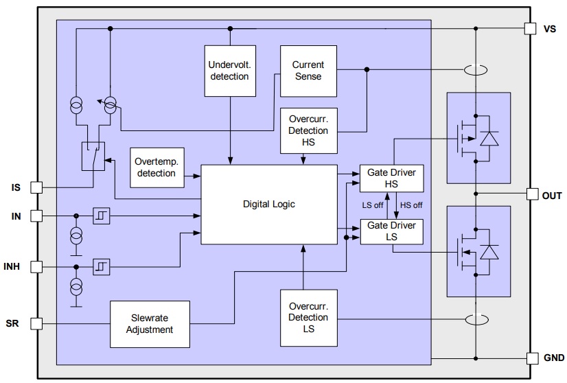
The IFX007T is an integrated high current half bridge for motor drive applications. It is part of the Industrial & Multi-Purpose NovalithIC™ family containing one p-channel high-side MOSFET and one n-channel low-side MOSFET with an integrated driver IC in one package. Due to the p-channel high-side switch the need for a charge pump is eliminated thus minimizing EMI. Interfacing to a microcontroller is made easy by the integrated driver IC which features logic level inputs, diagnosis with current sense, slew rate adjustment, dead time generation and protection against overtemperature, undervoltage, overcurrent and short circuit. The IFX007T provides a cost optimized solution for protected high current PWM motor drives with very low board space consumption.
Short circuit protection
The device provides embedded protection functions against
- output short circuit to ground
- output short circuit to supply voltage
- short circuit of the load
The short circuit protection is realized by the previously described current limitation in combination with the overtemperature shutdown of the device.
Input circuit
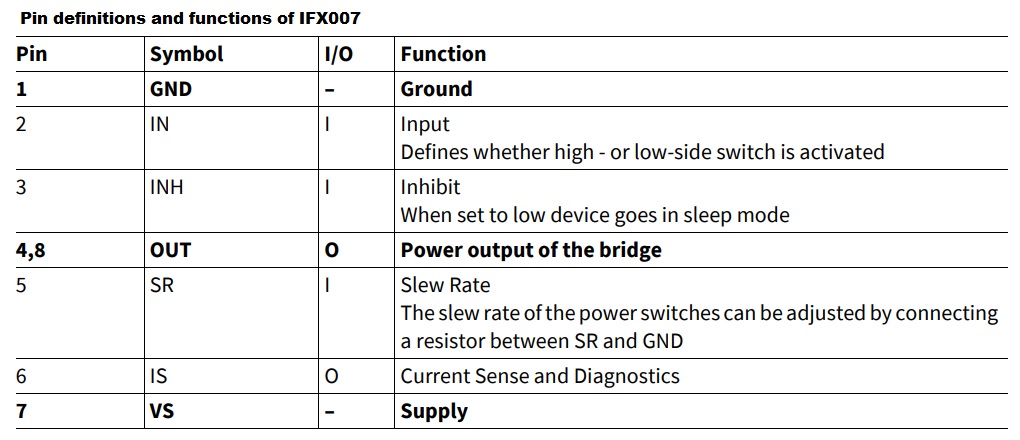
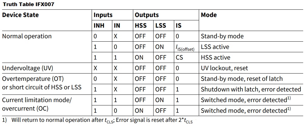
The control inputs IN and INH consist of TTL/CMOS compatible Schmitt triggers with hysteresis which controls the integrated gate drivers for the MOSFETs. Setting the INH pin to high enables the device. In this condition, one of the two power switches is switched on depending on the status of the IN pin. To deactivate both switches, the INH pin has to be set to low. No external driver is needed. The IFX007T can be interfaced directly to a microcontroller.
Deadtime generation
In bridge applications it has to be assured that the high-side and low-side MOSFET are not conducting at the same time, connecting directly the battery voltage to GND. This is assured by a circuit in the driver IC, generating a so-called dead time between switching off one MOSFET and switching on the other. The dead
time generated in the driver IC is automatically adjusted to the selected slew rate
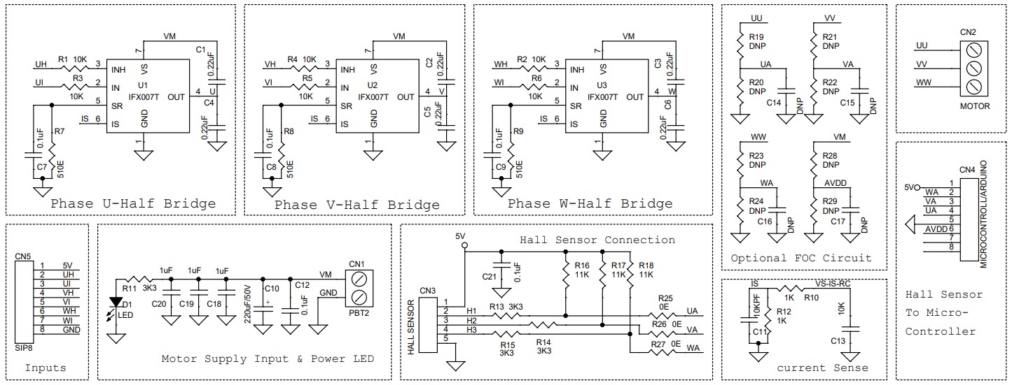
Adjustable slew rate (Adjustable Using External Resistor R7, R8, R9) Refer Data Sheet of IFX007 for more Info
In order to optimize electromagnetic emission, the switching speed of the MOSFETs is adjustable by an external resistor R7, R8, R9. The slew rate pin SR allows the user to optimize the balance between emission and power dissipation within his own application by connecting an external resistor RSR to GND.
Status flag diagnosis with current sense capability
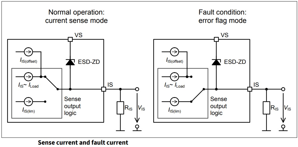
The sense pin IS is used as a combined current sense and error flag output. In normal operation (current sense mode), a current source is connected to the status pin, which delivers a current proportional to the forward load current flowing through the active high-side switch.
Schematic
Parts List
| NO | QNTY. | REF | DESC | MANUFACTURER | SUPPLIER | PART NO |
|---|---|---|---|---|---|---|
| 1 | 1 | CN1 | 2 PIN SCREW TERMINAL PITCH 5.08MM | PHOENIX | DIGIKEY | 277-1247-ND |
| 2 | 1 | CN2 | 3 PIN SCREW TERMINAL PITCH 5.08MM | PHOENIX | DIGIKEY | 277-1248-ND |
| 3 | 1 | CN3 | 5 PIN MALE HEADER CONNECTOR PITCH 2.54MM | WURTH | DIGIKEY | 732-5318-ND |
| 4 | 1 | CN4 | 8 PIN MALE HEADER PITCH 2.54MM | WURTH | DIGIKEY | 732-5321-ND |
| 5 | 1 | CN5 | 8 PIN MALE HEADER PITCH 2.54MM | WURTH | DIGIKEY | 732-5321-ND |
| 6 | 6 | C1,C2,C3,C4,C5,C6 | 0.22uF/50V SMD SIZE 1206 | MURATA/YAGEO | DIGIKEY | |
| 7 | 5 | C7,C8,C9,C12,C21 | 0.1uF/50V SMD SIZE 0805 | MURATA/YAGEO | DIGIKEY | |
| 8 | 1 | C10 | 220uF/50V ELECTROLYTIC | MURATA/YAGEO | DIGIKEY | |
| 9 | 1 | C11 | 10KPF/50V SMD SIZE 0805 | MURATA/YAGEO | DIGIKEY | |
| 10 | 7 | R1,R2,R3,R4,R5,R6,C13 | 10K 5% SMD SIZE 0805 | MURATA/YAGEO | DIGIKEY | |
| 11 | 12 | C14,C15,C16,C17 | DNP | |||
| R19,R20,R21,R22 | DNP | |||||
| R23,R24,R28,R29 | DNP | |||||
| 12 | 3 | C18,C19,C20 | 1uF/50V SMD SIZE 1206 | MURATA/YAGEO | DIGIKEY | |
| 13 | 1 | D1 | LED SMD SIZE 0805 | MURATA/YAGEO | DIGIKEY | 160-1427-1-ND |
| 14 | 3 | R7,R8,R9 | 510E 1% SMD SIZE 0805 | MURATA/YAGEO | DIGIKEY | |
| 15 | 2 | R10,R12 | 1K 1% SMD SIZE 0805 | MURATA/YAGEO | DIGIKEY | |
| 16 | 4 | R11,R13,R14,R15 | 3K3 5% SMD SIZE 0805 | MURATA/YAGEO | DIGIKEY | |
| 17 | 3 | R16,R17,R18 | 11K 5% SMD SIZE 0805 | MURATA/YAGEO | DIGIKEY | |
| 18 | 3 | R25,R26,R27 | 0E SMD SIZE 0805 | MURATA/YAGEO | DIGIKEY | |
| 19 | 3 | U1,U2,U3 | IFX007T | INFINION | DIGIKEY | IFX007TAUMA1CT-ND |
Connections
Block Diagram


