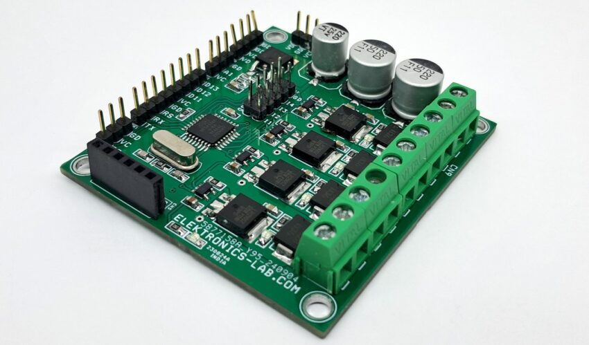
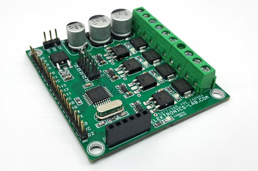
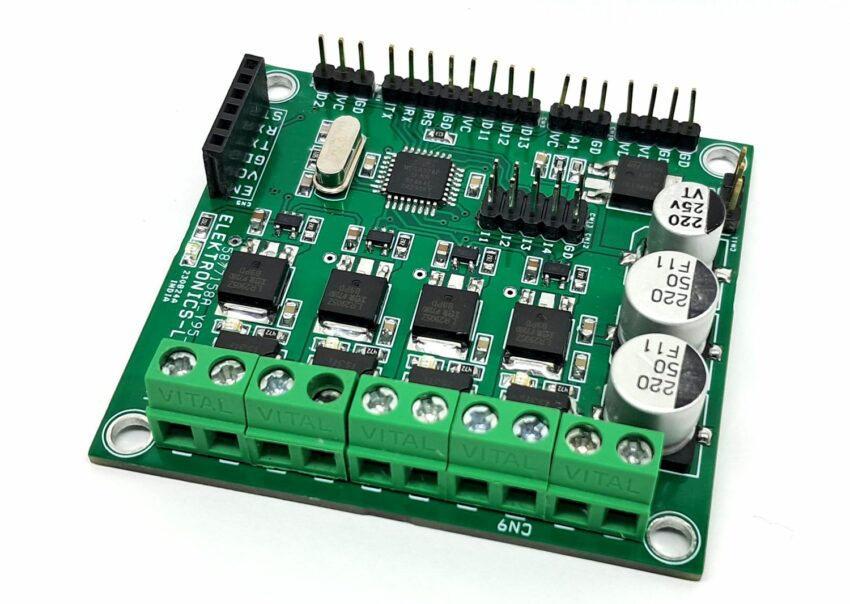
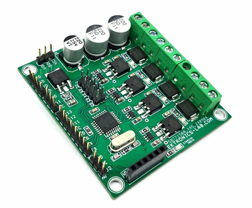
Bluetooth Smart LED Dimmer – 4 Channel Bluetooth ON/OFF Switch
- Rajkumar Sharma
- 78 Views
- medium
- Tested
- SKU: EL153807
- Quote Now
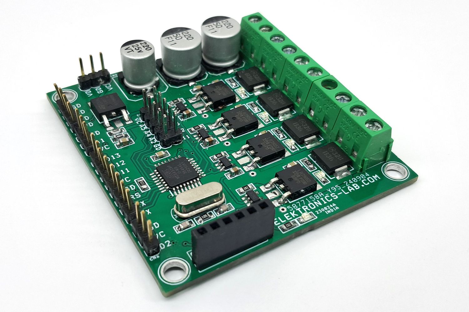
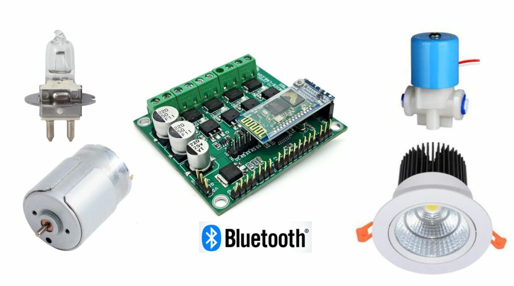
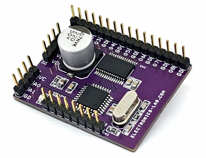
This Bluetooth Smart LED Dimmer, 4 Channel ON/OFF Switch is a versatile device that enables users to control various devices, including lights, fans, and DC motors, using a Bluetooth app on an Android device. The device features a 4-channel dimmer that can handle inductive or resistive loads with a power supply range of 12V to 48V and a current capacity of up to 3A per channel. The project is designed to work with DC loads and includes freewheeling diodes across all 4 MOSFETs to handle inductive loads such as DC motors and solenoids. The device requires a dual power supply, with a logic supply of 12V-15V and a load supply of 12V to 48V. However, it can also operate with a single supply of 12V-15V by tying the VDD and VL pins together.
Power Supply
- Logic Supply 12V to 15V
- Load Supply 12V to 48V
- Project Can work with Single Power, if the load supply is 12V to 15V (By Tying VDD and VL Pins)
- Load Each Channel 3A
Applications
- 4-channel on/off switch for LED, lamp, fan, and other devices
- 4-channel dimmer for adjusting brightness levels
- DC motor on/off control
- DC motor speed control
- 4-channel solenoid driver
Features
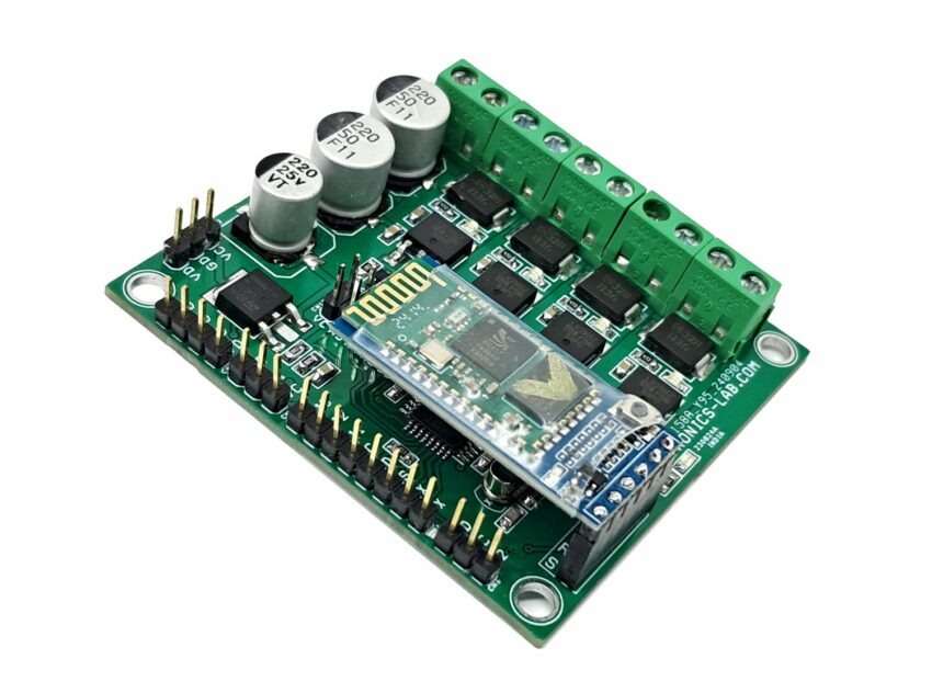
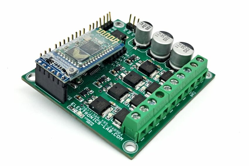
- ATMEGA328 microcontroller compatible with Arduino
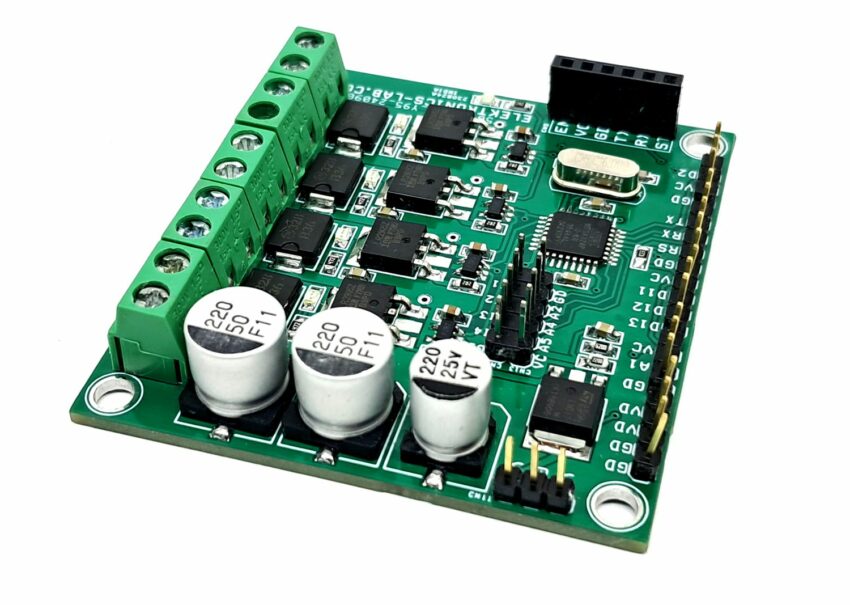
- 4 x MOSFETS for switching and dimming
- 4 x MOSFET gate driver for efficient switching
- HC-05 Bluetooth module for wireless connectivity
- Screw terminals for connecting loads and power supply
- Power LED indicator
- On Board Regulator to Power the Microcontroller (5V DC)
- 4 x LED indicators for channel output
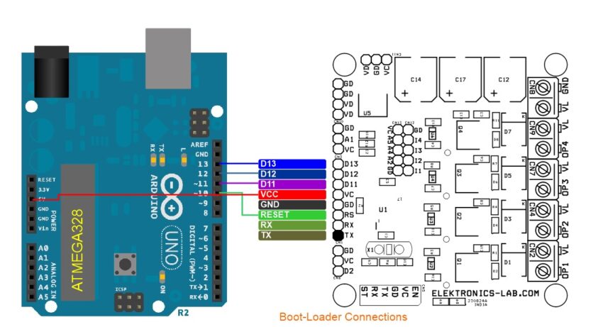
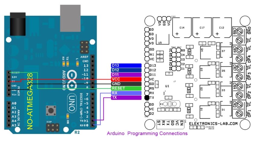
- 8-pin header connector for Arduino programming and bootloader
- High-Value DC Bus Capacitor for Smooth Operations
- 4 x 4 mm Mounting Holes
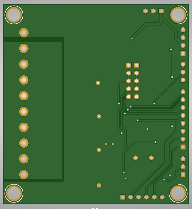
- PCB Dimensions 64.45 x 59.69 mm
Arduino Programming
Users must download and upload the Arduino code to the ATMEGA328 microcontroller to test the board. Before uploading the code, it is essential to ensure that the bootloader is installed on the new ATMEGA328. The connections diagram provides instructions for Arduino programming and bootloader installation.
Bootloader and Arduino Programming info
https://docs.arduino.cc/built-in-examples/arduino-isp/ArduinoToBreadboard/
Arduino Code
The Arduino code for the Bluetooth Smart LED Dimmer, 4 Channel ON/OFF Switch is available for download, allowing users to test the board and its various features. Additionally, an Android app is also available for download, which enables users to control the 4 loads (LED, lamp, fan, etc.) remotely using their Android device.
The Android app provides a user-friendly interface for turning the loads on and off, and users can also create their own code to implement dimming functionality for the LEDs and speed control for DC motors. The 4 x MOSFET drivers are connected to the PWM (Pulse Width Modulation) pins of the Arduino microcontroller, which enables precise control over the output voltage and current to the loads.
By using the PWM pins, users can adjust the brightness of the LEDs and the speed of the DC motors, making the device suitable for a wide range of applications. The availability of the Arduino code and Android app makes it easy for users to get started with the device and explore its various features and capabilities.
Overall, the Arduino code and Android app provide a comprehensive solution for controlling and managing the Bluetooth Smart LED Dimmer, 4 Channel ON/OFF Switch, making it an ideal choice for various applications, including home automation, robotics, and IoT projects.
Android App
https://github.com/engrpanda/Arduino-Bluetooth-Controller
Arduino Code
Arduino Pins
- Digital-PWM Pin D3, Output 1 (Load1)
- Digital-PWM Pin D5, Output 2 (Load2)
- Digital-PWM Pin D6, Output 3 (Load3)
- Digital-PWM Pin D9, Output 4 (Load4)
- Bluetooth Module: BT-RX>> Arduino TX, BT-TX>> Arduino RX
Connections
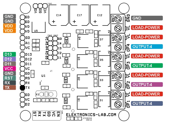
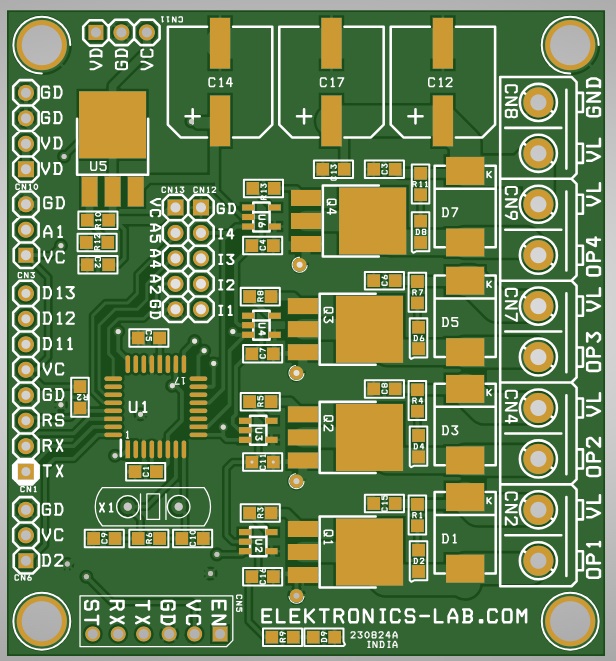
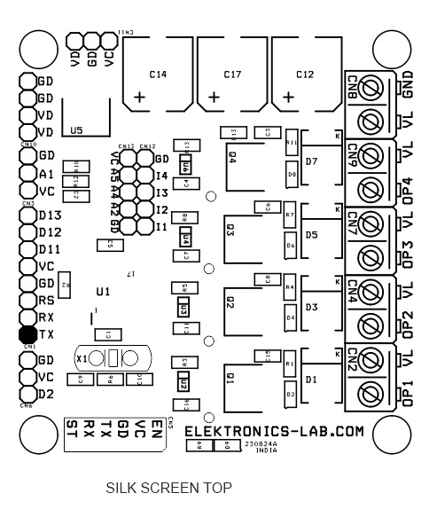
- CN1 Programming/Bootloader: Pin 1 = TX, Pin 2 = RX, Pin 3 = Reset, Pin 4 = GND, Pin 5 = VCC, Pin 6 = D11, Pin 7 = D12, Pin 8 = D13
- CN2: Pin 1 = +Load-1, Pin 2 = Load-1
- CN3: Optional No Use
- CN4: Pin 1 = +Load-1, Pin 2 = Load-2
- CN5: Optional No Use
- CN6: Optional No Use
- CN7: Pin 1 = +Load-3, Pin 2 = Load-3
- CN8 Power Supply: Pin 1 = 12V to 48V Load Power Supply, Pin 2 = GND
- CN9: Pin 1 = +Load-4, Pin 2 = Load-4
- CN10: Optional No Use
- CN11: Optional No Use
- D1: Power LED
- D2, D4, D6, D8: Function LED – 4 Channel
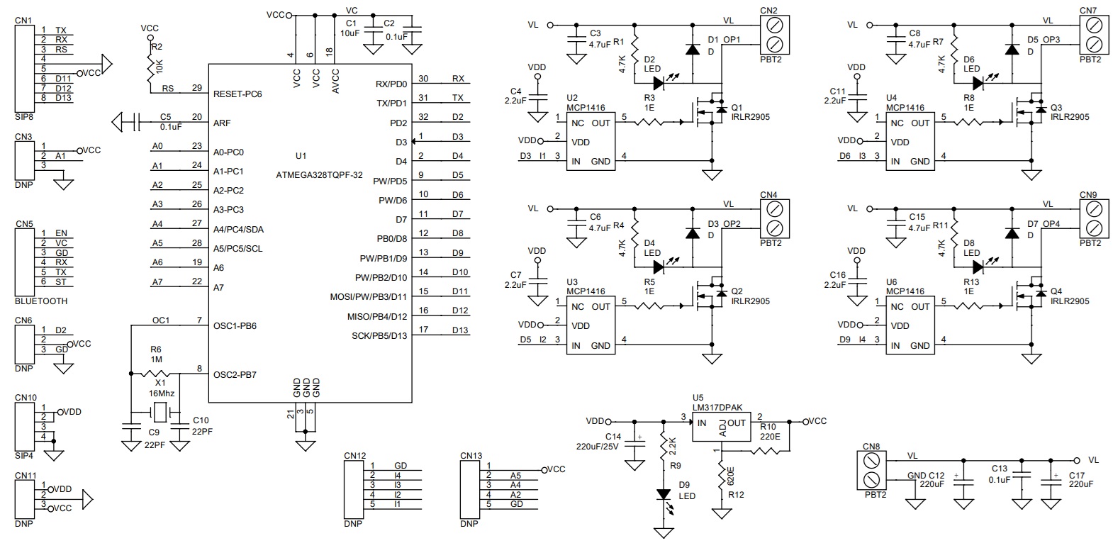
Schematic
Parts List
| NO. | QNTY. | REF. | DESC. | MANUFACTURER | SUPPLIER | SUPPLIER PART NO |
|---|---|---|---|---|---|---|
| 1 | 1 | CN1 | 8 PIN MALE HEADER PITCH 2.54MM | WURTH | DIGIKEY | 732-5321-ND |
| 2 | 5 | CN2,CN4,CN7,CN8,CN9 | 2 PIN SCREW TERMINAL PITCH 5.08MM | SCREW TERMINAL | DIGIKEY | 277-1247-ND |
| 3 | 5 | CN3,CN6,CN11,CN12,CN13 | DNP | |||
| 4 | 1 | CN5 | BLUETOOTH MODULE HC-05 | AMAZON/EBAY | DIGIKEY | |
| 5 | 1 | CN10 | 4 PIN MALE HEADER PITCH 2.54MM | WURTH | DIGIKEY | 732-5317-ND |
| 6 | 1 | C1 | 10uF/16V CERAMIC SMD SIZE 0805 | YAGEO/MURATA | DIGIKEY | |
| 7 | 3 | C2,C5,C13 | 0.1uF/50V CERAMIC SMD SIZE 0805 | YAGEO/MURATA | DIGIKEY | |
| 8 | 4 | C3,C6,C8,C15 | 4.7uF/50V CERAMIC SMD SIZE 0805 | YAGEO/MURATA | DIGIKEY | |
| 9 | 4 | C4,C7,C11,C16 | 2.2uF/25V CERAMIC SMD SIZE 0805 | YAGEO/MURATA | DIGIKEY | |
| 10 | 2 | C9,C10 | 22PF/50V CERAMIC SMD SIZE 0805 | YAGEO/MURATA | DIGIKEY | |
| 11 | 2 | C12,C17 | 220uF/50V ELEKTROLYTIC | RUBYCON | DIGIKEY | 1189-1654-1-ND |
| 12 | 1 | C14 | 220uF/25V ELEKTROLYTIC | PANASONIC | DIGIKEY | PCE3800CT-ND |
| 13 | 4 | D1,D3,D5,D7 | MBRS360 | VISHAY | DIGIKEY | VS-MBRS360-M3/9ATGICT-ND |
| 14 | 5 | D2,D4,D6,D8,D9 | LED RED SMD SIZE 0805 | OSRAM | DIGIKEY | 475-1278-1-ND |
| 15 | 4 | Q1,Q2,Q3,Q4 | IRLR2905 DPAK | INFINEON | DIGIKEY | IRLR2905ZTRPBFCT-ND |
| 16 | 4 | R1,R4,R7,R11 | 4.7K 5% SMD SIZE 0805 | YAGEO/MURATA | DIGIKEY | |
| 17 | 1 | R2 | 10K 5% SMD SIZE 0805 | YAGEO/MURATA | DIGIKEY | |
| 18 | 4 | R3,R5,R8,R13 | 1E 5% SMD SIZE 0805 | YAGEO/MURATA | DIGIKEY | |
| 19 | 1 | R6 | 1M 5% SMD SIZE 0805 | YAGEO/MURATA | DIGIKEY | |
| 20 | 1 | R9 | 2.2K 5% SMD SIZE 0805 | YAGEO/MURATA | DIGIKEY | |
| 21 | 1 | R10 | 220E 1% SMD SIZE 0805 | YAGEO/MURATA | DIGIKEY | |
| 22 | 1 | R12 | 620E 1% SMD SIZE 0805 | YAGEO/MURATA | DIGIKEY | |
| 23 | 1 | U1 | ATMEGA328TQPF-32 | MICROCHIP | DIGIKEY | ATMEGA328P-AU-ND |
| 24 | 4 | U2,U3,U4,U6 | MCP1416 | MICROCHIP | DIGIKEY | MCP1416T-E/OTCT-ND |
| 25 | 1 | U5 | LM317DPAK | TI | DIGIKEY | LM317MDTNS/NOPB-ND |
| 26 | 1 | X1 | 16Mhz | ECS INC | DIGIKEY | X1103-ND |
Connections
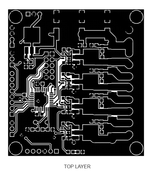
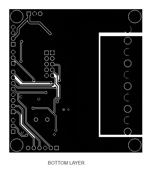
Gerber View
Photos
Video


