Bomb Game
- Rui Cabral
- http://www.ruijc.webnode.com
- rui.j.cabral@googlemail.com
- 36.969 Views
- moderate
- Non tested
Introduction
“Should I cut the blue wire… or the red…?” This is a very common phrase in many movies when the action hero has a bomb in front of him with little time left and he has to choose which wire to cut and stop the bomb from exploding saving millions of people.
This game is just that… a count down timer and 4 wires of different colors. The player has to remove each wire until it deactivates the bomb.
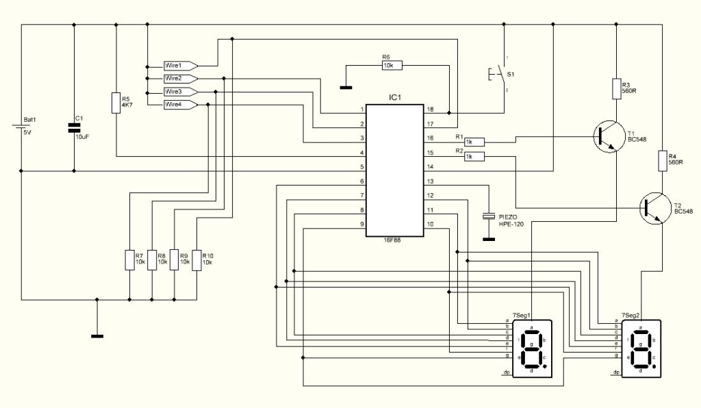
Schematic
Parts List
R1 1K ohms resistor
R2 1K ohms resistor
R3 560 ohms resistor
R4 560 ohms resistor
R5 4K7 ohms resistor
R6 10K ohms resistor
R7 10K ohms resistor
R8 10K ohms resistor
R9 10K ohms resistor
R10 10K ohms resistor
C1 10uF capacitor
T1 BC548 Transistor
T2 BC548 Transistor
Piezo HPE-120 piezo
Digits Dual 7 segment display – LTD6410G
IC1 16F88 microcontroller from Microchip
S1 Push button
Others:
Box
PCB
Wires
4.8V Battery Pack
Hex program for the microcontroller
PCB
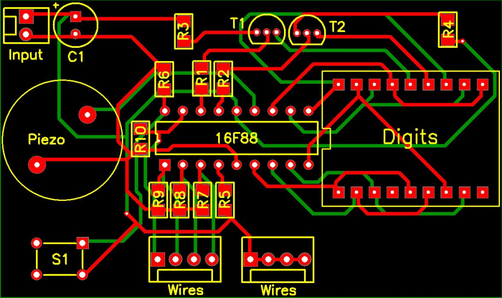
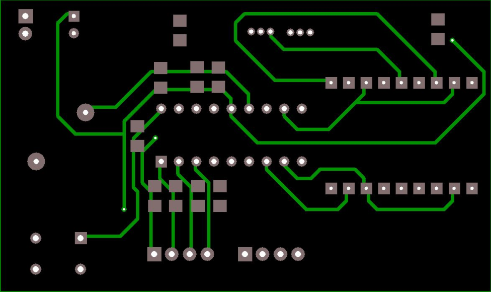
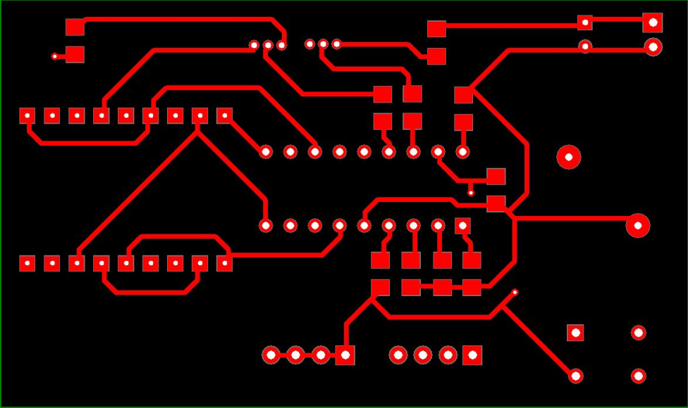
I’ve decided to build my version on a breadboard because it has a more realistic look. All the wires and components create a better game experience. Anyway I have made a pcb drawing making it possible to create a clean build. The PCB used for this Project is double layer and its size is 70.79 mm x 42.01 mm. Download the PCB files on the bottom.
How it works
Turning the power on, the display and piezo will start small introduction.
After the introduction, the message “S1” will appear on the display meaning that S1 needs to be pressed for the game to start.
All four wires must be plugged in. If one of the wires is not plugged in, the message “EE” will display meaning that an error occurred and the game will not begin.
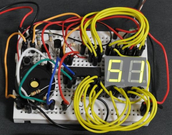
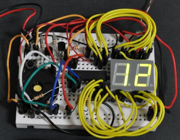
As the game begins, the count down will start. The display shows the timer and 15 seconds is all the time we have to defuse the bomb.
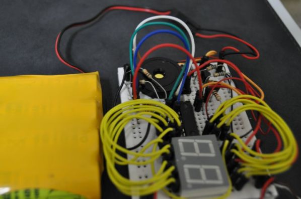
There are four wires – red, green, blue and white. Unplugging them will simulate the cutting of the wire. Only one wire can be unplugged at a time and each wire can only be used once per play.
There are four actions possible – defuse the bomb, explode the bomb, increase timer speed and no consequence.
There is no need to change the color position because each position will correspond to a random action.
Every time a wire is unplugged, its action will be randomly given meaning that it’s possible that even all of the wires will not defuse the bomb.
Main menu – waiting for S1 to be pressed to start the game
Counting down – time to choose which wire to pull
Four wires – red, blue, green and white
Hex Program
The Hex program named Bgame.Hex must be saved in the 16F88 microcontroller’s memory before soldering on the PCB. Download HEX in the files at the bottom.
Testing
A video of this project working can be found at the link: http://www.youtube.com/watch?v=YnFUfPpllh8
Conclusion
It’s an original game and can bring a lot of fun to the kids.
For a final look it’s possible to cut 3 pieces of PVC tube, paint them in red and glue the circuit on the tubes. This will make the traditional look of the dynamite bomb.




Would you please to send me the source code?
I want to study more about it, and I want to try new things on CCompiler.
We are sorry, only .hex file is available, you may try to contact the author.
How do I get the hex file on the 16f88 microcontroller
You will need a PIC programmer like PICkit2 or K150 connected to the microcontroller and your PC running a programming software.
what software do I need to get to put the hex on the chip
It depends on which programmer do you have. Usually the programmer comes with it’s software.
What’s the point if you don’t include any source file ? And your PCB is not optimized for low quality made, your routes are too much thin.
We are sorry, the source code for this project is not available from the author. Also the PCB definitely needs more work.
Does this work? Before I spend the money on it.
This has not been tested in our lab, so you always take this in consideration when building it. According to author this works and the video proves that.