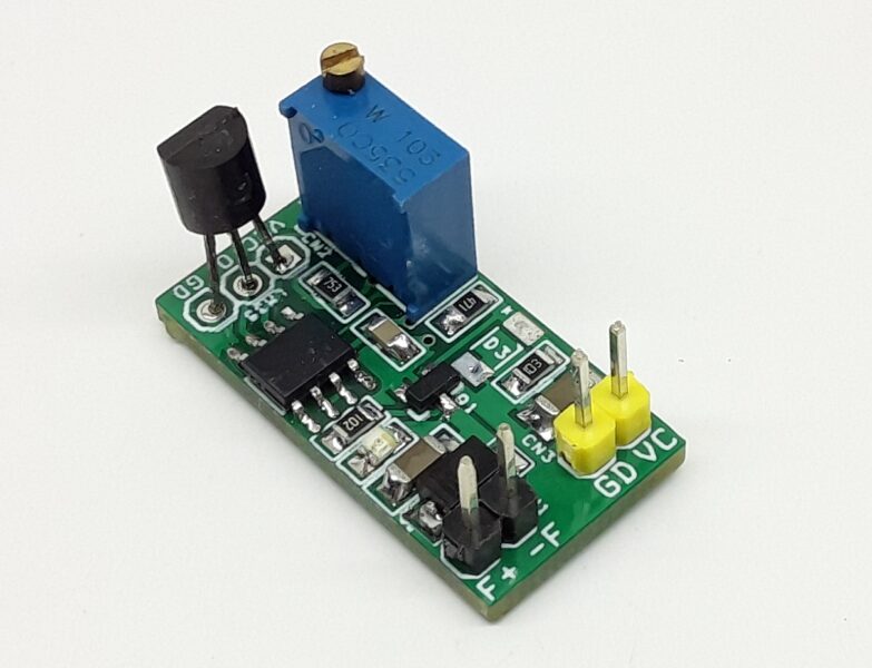
Distance Measuring Sensor Shield for Arduino Nano Using GP2Y0D810Z0F
- Rajkumar Sharma
- 5.474 Views
- easy
- Tested
- SKU: EL69885
- Quote Now
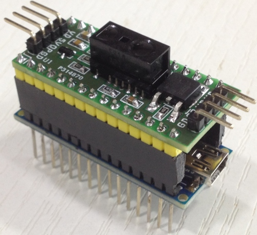
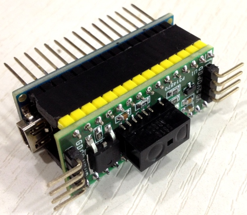
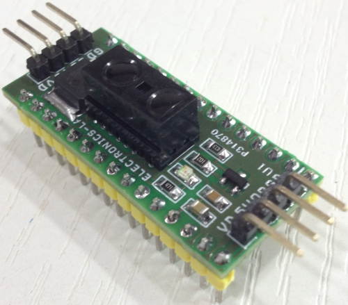
The project published here is a distance measuring sensor shield for Arduino Nano including power driver BJT transistor to drive a load like solenoid, motor or LED. This project can be used as Arduino shield or as stand-alone sensor.
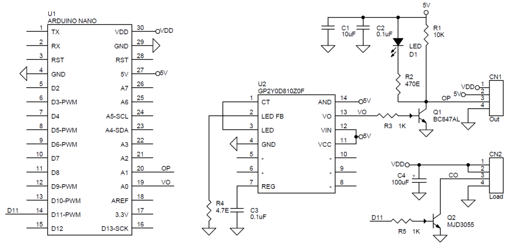
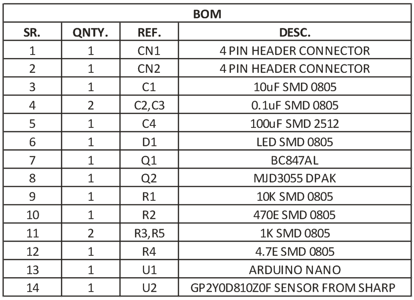
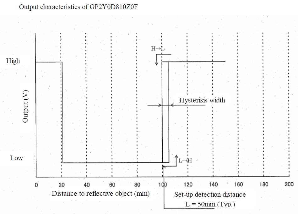
GP2Y0D810Z0F from Sharp is heart of the project, The sensor is a composed of an integrated combination of PD (photo diode) , IRED (infrared emitting diode) and signal processing circuit. The variety of the reflectivity of the object, the environmental temperature and the operating duration are not influenced easily to the distance detection because of adopting the triangulation method. The output voltage of this sensor stays high in case an object exists in the specified distance range. So this sensor can also be used as proximity sensor. Output is normally High and it goes low when it detects the object. The output VO is connected to Analog pin A0 of the Arduino Nano. Q1 Transistor helps to inverse the output which also controls the LED. This inversed output also connected to Analog pin A1 of Arduino. Digital pin D11 goes to base of Q2 power NPN BJT transistor MJD3055. This transistor provided to develop high power load driving application like Auto flush, Auto LED on/off when object is detected etc.
Features
- Supply 5V (2.7V To 6.2V Standalone Mode)
- Current Consumption 10mA
- Detection Range 20MM- 100MM
- Sun Light Tolerance
- Output LED
- Measuring Operating Duration 1.28ms
- Measuring Duration V Output 2.56ms
Application
- Touch less Switch
- Sanitary Equipment
- Robot Cleaner
- Control of Illumination
Operation Of Sensor
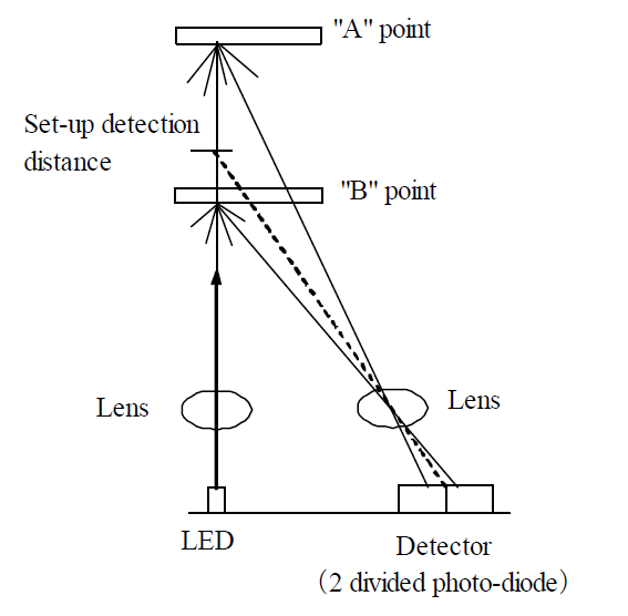
Optical spot position on the detector (2 divided photo-diode) shall be changed when reflective object is at “A” point and at “B” point. In case that the position of the photodiodes is set as the reflected light at the setup detection distance makes a spot on the center of the photodiodes, the reflected light at “A” point comes onto the left photodiode and the reflected light at “B” point comes onto the right photodiode. So by processing the detecting light amount ratio between these two photodiodes, this sensor can judge as detection at “B” point and a non-detection at “A” point.
Schematic


