Fuel Gauge with OLED Display
- Rajkumar Sharma
- 61 Views
- easy
- Tested
- SKU: EL153860
- Quote Now
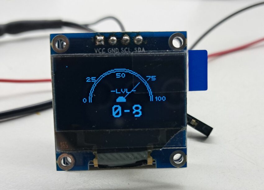
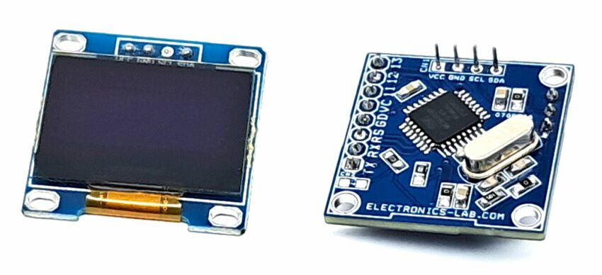
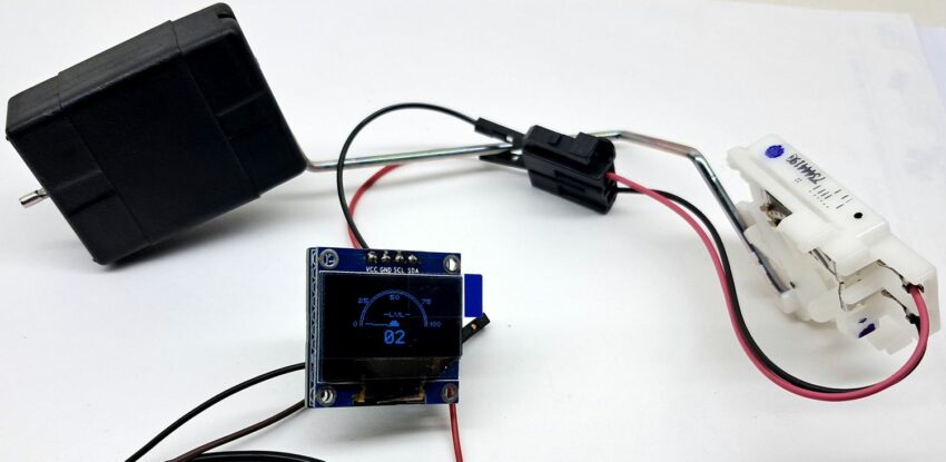
This project enables the measurement of fuel levels in a tank using a resistive float sensor. The fuel level is measured and displayed on an OLED display. The project is compatible with Arduino and features an ATMEGA328 microcontroller. The resistive sensor, connected to a divider resistor, is linked to Analog pin A0 of the Arduino chip. The OLED display is connected to the I2C pins of the microcontroller. Overall, the OLED display with needle-type visualization and 0 to 100% fuel capacity range provides a clear, accurate, and easy-to-read indication of the fuel level, making it an essential feature in modern vehicles.
Arduino Code
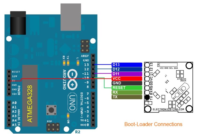
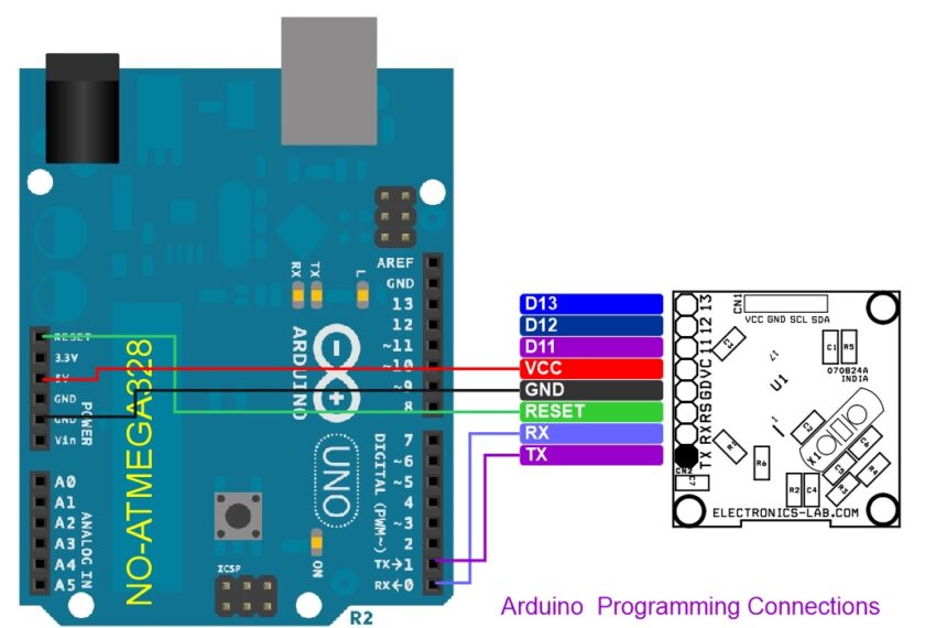
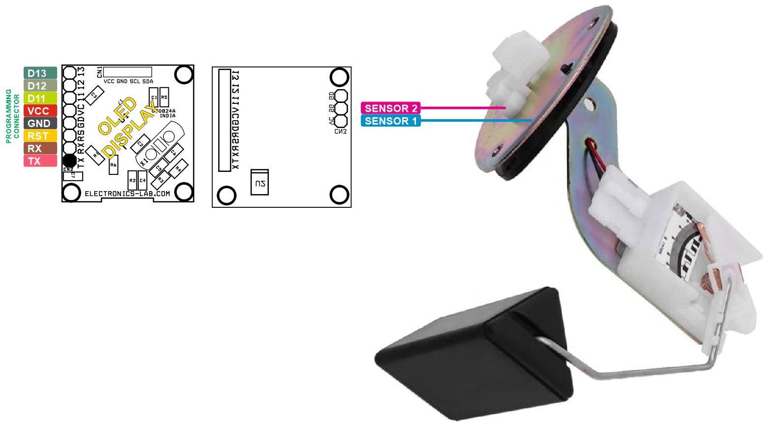
The Arduino code for testing the project is available in downloads. To utilize the code, load the bootloader and upload the code to a new ATMEGA328 microcontroller using the onboard programming connector. Please refer to the connection diagram for guidance.
Bootloader: https://docs.arduino.cc/retired/hacking/software/Bootloader/
Arduino Bootloader and Arduino Programming: https://docs.arduino.cc/built-in-examples/arduino-isp/ArduinoToBreadboard/
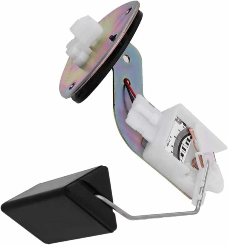
Sensor
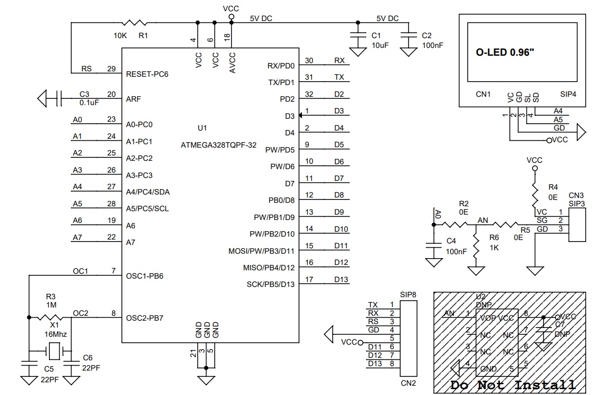
The resistive sensor is employed to measure the fuel level, and when paired with a 1K divider resistor, it produces an analog value ranging from 795 to 980. This analog signal is then connected to the Analog-to-Digital Converter (ADC) pin A0 of the Arduino chip. The Arduino chip evaluates the input signal and subsequently displays the fuel level on the OLED display.
Features
- Power Supply 5V DC
- 9.6″ OLED Display
- Arduino Compatible Project
- Project Accommodates Any Resistive Sensor 2-Wire or 3-Wire
- On Board Connector for Bootloader and Arduino Programming
- PCB Dimensions 27.62 x 28.73mm
Arduino Pins
- Sensor Input Analog-0 Arduino
- Arduino A4= SDA – OLED Display
- Arduino A5 = SCL – OLED Display
Connections
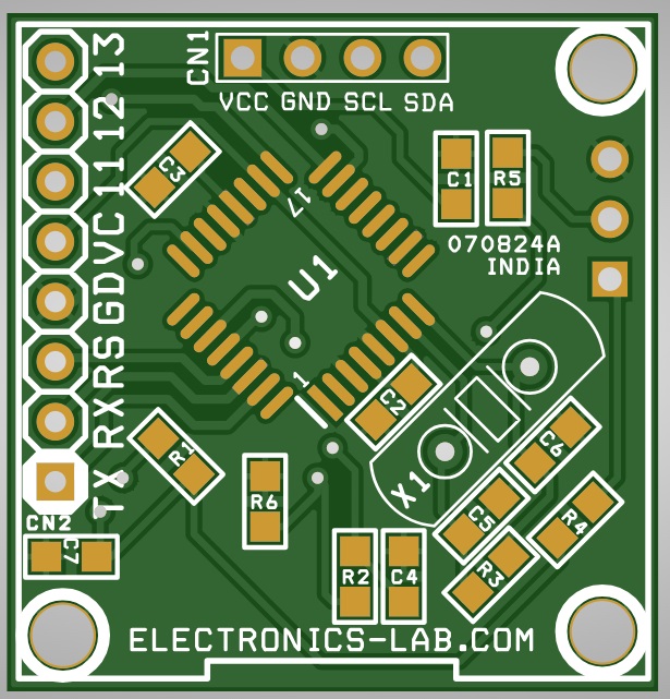
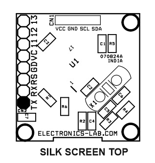
- CN1: OLED Display, Pin 1 = VCC, Pin 2 = GND, Pin 3 = SCL, Pin 4 = SDA
- CN1: Programming Connector, Pin 1 = TX, Pin 2 = RX, Pin 3 = Reset, Pin 4 = GND, Pin 5 = VCC, Pin 6 = D11, Pin 7 = D12, Pin 8 = D13
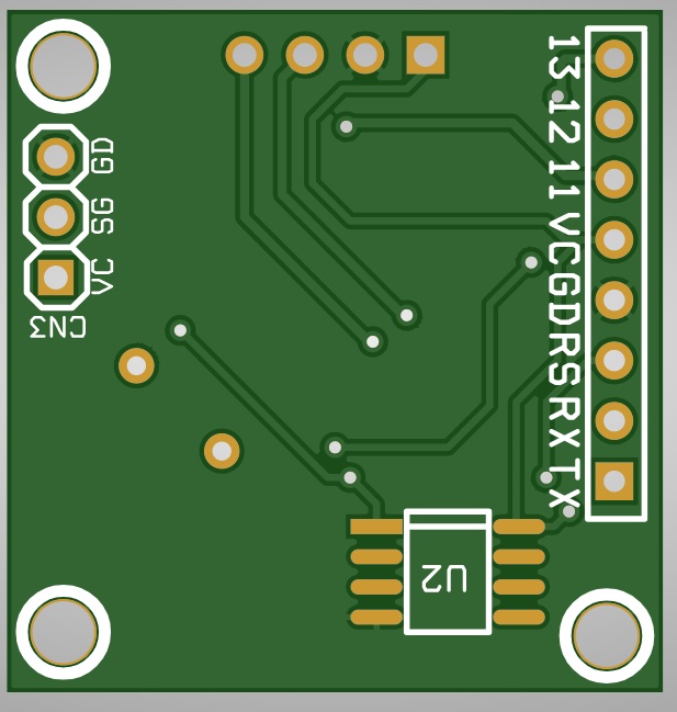
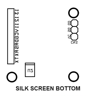
- CN3: Sensor Connection, Pin 1 = Sensor 1 (VCC), Pin 2 = Sensor 2 (Analog A0), Pin 3 = GND Note in Use
Schematic
Parts List
| QNTY. | QNTY. | REF. | DESC. | MANUFACTURER | SUPPLIER | SUPPLIER PART NO |
|---|---|---|---|---|---|---|
| 1 | 1 | CN1 | OLED DISPLAY 0.96INC 128X64 | WINSTAR | DIGIKEY | 4863-WEA012864DWPP3N00003-ND |
| 2 | 1 | CN2 | 8 PIN MALE HEADER PITCH 2.54MM | WURTH | DIGIKEY | 732-5321-ND |
| 3 | 1 | CN3 | 3 PIN MALE HEADER PITCH 2.54MM | WURTH | DIGIKEY | 732-5316-ND |
| 4 | 1 | C1 | 10uF/10V CERAMIC SMD SIZE 0805 | YAGEO/MURATA | DIGIKEY | |
| 5 | 3 | C2,C3,C4 | 100nF/25V CERAMIC SMD SIZE 0805 | YAGEO/MURATA | DIGIKEY | |
| 6 | 2 | C5,C6 | 22PF/50V CERAMIC SMD SIZE 0805 | YAGEO/MURATA | DIGIKEY | |
| 7 | 2 | U2,C7 | DNP | |||
| 8 | 1 | R1 | 10K 5% SMD SIZE 0805 | YAGEO/MURATA | DIGIKEY | |
| 9 | 3 | R2,R4,R5 | 0E SMD SIZE 0805 | YAGEO/MURATA | DIGIKEY | |
| 10 | 1 | R3 | 1M 5% SMD SIZE 0805 | YAGEO/MURATA | DIGIKEY | |
| 11 | 1 | R6 | 1K 5% SMD SIZE 0805 | YAGEO/MURATA | DIGIKEY | |
| 12 | 1 | U1 | ATMEGA328TQPF-32 | MICROCHIP | DIGIKEY | ATMEGA328P-AU-ND |
| 13 | 1 | X1 | 16Mhz | ECS INC | DIGIKEY | X1103-ND |
Connections
Gerber View
Photos


